Anderson ANM75 User manual

No:
ATS–Operation Manual–ANM75
Subject::
ANM75 Burner Operation Manual
Version :
V1.0
Author :
Wilson Sun
Review :
David
Anderson Thermal Solutions (Suzhou) Co., LTD
ANM75 Burner Operation Manual

CONTENT
1. Disclaimer Notice .......................................................................................................................................1
2. Liability And Warranty ...............................................................................................................................1
3. Safety Guide...............................................................................................................................................1
4. Fuel Information ........................................................................................................................................2
5. ANM75 Series Burner Description .............................................................................................................2
6. Burner Component Introduction ...............................................................................................................3
7. Burner Operation Data ..............................................................................................................................4
8. Performance Curves...................................................................................................................................4
9. Burner datasheet .......................................................................................................................................4
10. Burner Installation .....................................................................................................................................5
10.1 Storage: ..............................................................................................................................................5
10.2 Handing ..............................................................................................................................................5
10.3 Pre–Installation Checklist ...................................................................................................................5
10.4 Environment.......................................................................................................................................5
10.5 Burner Mounting................................................................................................................................6
10.6 Checklist after installation..................................................................................................................7
10.7 Prepare for adjustment ......................................................................................................................7
10.8 Burner starting ...................................................................................................................................8
10.9 Stop Procedure...................................................................................................................................9
11. Burner Maintenance..................................................................................................................................9
11.1 Half a year checklist............................................................................................................................9
11.2 Yearly checklist ...................................................................................................................................9
12. Troubleshooting Procedures....................................................................................................................10
13. Appendix ..................................................................................................................................................13
13.1 List of Spare Parts of the Burner ......................................................................................................13
13.2 Spare parts reference figure.............................................................................................................14
13.3 Operation Manual Record................................................................................................................14
13.4 Half Year Audit Record .....................................................................................................................15
13.5 Yearly Audit Record ..........................................................................................................................15

Anderson Thermal Solutions – ANM75 Burner Operation Manual
Anderson Thermal Soluions(Suzhou)Co. ,Ltd.
1
This manual has been written for those who are already familiar with all aspects of nozzle
mix burner and its add-on components. Main contents of the manual including safety rules,
burner installation, commissioning, operation parameters, maintenance and
troubleshooting, spare parts, etc.
1. Disclaimer Notice
Anderson Thermal Solutions (Suzhou) Co., Ltd. reserves the right to change the
construction and/or configuation of our product at any time without informing customers.
If the product or its individual modules are used for purposes other than the designated
purpose, their effectiveness and suitability must be confirmed.
Anderson warrants that the product itself will not infringe any patents. Every effort has
been made to make this manual as accurate and complete as possible. If you find errors or
omissions, please contact us so we can correct them.
2. Liability And Warranty
Due to negligence, breach of warranty or other reasons, Anderson's liability for its products
is limited to the provision of such replacement parts and will not be liable for any other
injury, loss or expense, whether direct or indirect, including but not limited to Loss of or
damage to the use of materials that sell, install, use, fail to use or repair or replace Anderson
related products.
The warranty is void if: any operation explicitly prohibited in this manual, any adjustment
or assembly process not recommended or authorized.
3. Safety Guide
Only those who were trained and qualified person can follow the manual to operate or
adjust the combustion system. The fire was prohibited within a radius of 5 meters of the
combustion system. Flame, non–covered light sources or heat sources shall not be brought
to the combustion area unless it is related to the process. Welding in combustion control
area shall be approved to ensure the safety in the area and also preventive measures
should be taken into consideration.
Before starting, the operator must confirm whether the burner and gas pipeline are in
normal working condition, and there is no flammable substance around the burner. The
burner must be operated with fuel and oxygen or air. The ignition and operation of the
burner must be performed at the specified position. The burner has been correctly and
safely installed before ignition. The ignition of the burner needs to be performed after the

Anderson Thermal Solutions – ANM75 Burner Operation Manual
Anderson Thermal Soluions(Suzhou)Co. ,Ltd.
2
combustion chamber is purged. If it is ignited at a low temperature, it needs to be replaced
with 5 times the volume of the combustion chamber to avoid explosion.
However, it is not necessary to purge when the temperature is higher than 750°C. Air pipe
or gas pipe connected with burner should be tight enough with no leakage, also the
periodically check air or fuel nozzles of the burners to prevent to be blocked by dust, slag
or other materials.
ATTENTION:DANGER OF BEEN BURNT
When burner in operation, combustion is severe, so the burner must be fixed. Hoses or
cables in area of the combustion system must be suitable for high temperature, to prevent
high temperature failure or cause safety accidents. Burners should be periodically
inspected and cleaned. Copper wire brush may be used, if necessary, to clean burner head.
The burner system should be checked twice a year for safety operation.
Burner commissioning shall take care of ignition position, minimum and maximum output
position. Following interlocks will cause emergency stop, including gas low pressure, high
pressure or low combustion air pressure, as well as emergency stop is trigged, the main
power is out, UV signal failure or kiln safety conditions (such as high temperature limit, flue
system opening, etc.) will cause the burner lockout. Users need to know the maintenance
interval recommended by the manufacturer and the interval specified by national laws,
whichever is shorter.
4. Fuel Information
Following table shows combustion fuel characters of natural gas and oxygen, safety rules
must be obeyed when operation carried out.
Fuel
Natural gas
Low Calorific value
35,900 [kJ/m3]
Composition
>98% CH
4
Reference conditions
1,013.25 mbar, 0°C
5. ANM75 Series Burner Description
ANM75 series Burners are line type burner, ideal for generating large volumes of clean, hot
air, used for ovens, dryers, fume incinerators, and similar industrial equipment.
Burners are constructed of carbon steel burner bodies and stainless steel air wings. The
burner bodies supply fuel to the center of the air wings.

Anderson Thermal Solutions – ANM75 Burner Operation Manual
Anderson Thermal Soluions(Suzhou)Co. ,Ltd.
3
The air and fuel mixture inside the burner are controlled by air wing design and gas nozzles
to optimize emissions and efficiency.
ANM75 series burner are modular design, can assembled from straight sections to various
shape, allowing for customized heat inputs. Blower connects with burner air duct to
provide combustion air with correct air flow and pressure. Brackets are available for slot
firing or duct mounting and flanges are available for continuous flange mounting. Gas flow
is controlled by gas control valve. Ignition can be by direct spark or by ignition pilot. Flame
rod supervision can be from either one end or both ends. Combustion air flow (DP) switch
and process air DP switches are factory mounted on the burner.
ANM75 Series Burner Advantage:
–An integral combustion air blower can be ordered mounted on the back of the burner,
to provide combustion air.
–Stable operation over a wide range of duct velocities from 1.5m/s to 30m/s without
installing a profile plate around the burner.
–High turn down ratio to 40:1 to match different requirement.
–The modular design, length of each module is 300 mm. Output of each module can
get as high as 300KW, different modules can be installed with shape of line shape, "I"
shape, "T" shape or “+” shape according to customer requirement.
–Only 10% excess air is needed when burner run at high fire.
–Reliable operation performance, once commissioning is complete, it is stable under
same condition, no need extra adjustment or maintenance.
–Burner suit for different gas fuel such as natural gas, LPG or hydrogen.
6. Burner Component Introduction
75ANM series burners are mainly made up of air wings, gas channel, peripheral fixing
device and connecting devices. Air wings were fixed by rivets, different components are
connected together with rivets or bolts to form the Burner body. Shown as below Fig 1 is
exploded drawing view, in which the air wing and outer connectors are made of stainless
steel, gas channels and connectors are cast iron.
Fig 1. ANM75 Series Burner Explosion View

Anderson Thermal Solutions – ANM75 Burner Operation Manual
Anderson Thermal Soluions(Suzhou)Co. ,Ltd.
4
7. Burner Operation Data
–Maximum input: 990 kW/m (when air DP across burner is 2.5mbar)
–Minimum input: 24 kW/m
–Fuel inlet pressure: 22 mbar
–High fire flame length: 1100mm. (when air DP across burner is 2.5mbar, the lower air
DP, the longer flame)
–Upstream temperature limit: –30°C to 400°C
–Downstream temperature limit:800°C
–Ignition: Direct Spark Ignition or pilot ignition
–Flame detection: Flame rod or UV scanner
–Fuels: Natural Gas, Propane, hydrogen
Remark:
Air DP across burner means air pressure difference between burner inlet and chamber, gas
pressure different means gas pressure difference between burner inlet and chamber.
8. Performance Curves
The operation and emission curves of the ANM75 series burner is shown in figure 2 and
figure 3.
Fig 2. ANM75 Series Burner Operation Fig 3. ANM75 Series Burner emission
9. Burner datasheet
The input and flame length curves of the ANM75 series burner is shown in figure 4 and 5

Anderson Thermal Solutions – ANM75 Burner Operation Manual
Anderson Thermal Soluions(Suzhou)Co. ,Ltd.
5
Fig 4. ANM75 Series Burner Input Curve Fig5. ANM75 Series Burner Flame Length Curve
10. Burner Installation
10.1 Storage:
1. Make sure that the area is clean.
2. Store the components in a cool, clean, dry room.
3. Keep the components in the original package as long as possible
10.2 Handing
1. Make sure that the components are clean and free of damage.
2. Protect the components from weather, damage, dirt and moisture.
3. Protect the components from excessive temperatures and humidity.
4. Use appropriate support equipment, i.e., harnesses, straps, chains etc. when lifting
burner components.
10.3 Pre–Installation Checklist
If there are corrosive fumes or materials in the surrounding air, find a clean air source
to supply to the burner. Observe ambient temperature limits as stated in Datasheet.
Combustion air from outside of burner room, needs at least 6 cm2per 1 kW to supply
sufficient fresh, outdoor combustion air.
Combustion air from inside duct, there must be a minimum of 18% O2 present in the
process air flow to ensure proper burner performance.
Do not allow exhaust gases to accumulate in the work area. Provide a means for
exhausting these gases from the building by blower, install the burner so it may be
easily accessed for inspection.
10.4 Environment
Be sure the burner operating environment matches the original operating
specifications. Check the following items:
–Voltage, frequency, and stability of electrical power

Anderson Thermal Solutions – ANM75 Burner Operation Manual
Anderson Thermal Soluions(Suzhou)Co. ,Ltd.
6
–Fuel type and fuel supply pressure
–Adequate fresh, clean, combustion air
–Humidity, altitude, temperature and presence of damaging corrosive gases of the
supply air.
10.5 Burner Mounting
1. Mounting methods
The installation modes of ANM75 series burners are as follows: process air parallel
to combustion flame, process air vertical to combustion flame, the former can be
divided into blower installed in the air duct and outside the air duct, the specific
diagram shows as fig 6 that the air duct burner installed in the center of the air duct.
Fig 6. ANM 75Series Burner Installation Layout
2. Corner distance
When laying in the duct, allow least length downstream of the burner should be
1100mm to avoid flame impingement; as fig 7 below shown, please see fig 5 for
flame length.
Fig 7. ANM75 Series Burner Installation Layout
When burner longer than 900 mm, use a hanger or a pedestal to support the blower
and motor. Process air velocity must be within the limits.

Anderson Thermal Solutions – ANM75 Burner Operation Manual
Anderson Thermal Soluions(Suzhou)Co. ,Ltd.
7
3. Profile Plate Adjust
Provide an opening in the duct 80mm larger than the external burner dimensions
gap on all 4 sides.
Profile plates are not required for good burner operation, but uniform velocity must
be maintained for the full length of the burner. If velocity is not uniform, profile
plates can be used to correct this condition. Profile plates should be positioned
flush with the firing end of the burner. If necessary, the plates can be located up to
1/2” back from the firing end, but under no circumstances should they be in front
of the burner.
4. Valve train connection
Locate the valve train as close as possible to the burner to make sure gas reach the
burner during the trial for ignition time. Sufficiently size shut off valves in the valve
train. In order to decrease pressure loss in pipe, minimize piping elbows to be used
while pipe union is recommended. Flexible pipe is good optional but pressure lost
must be considered.
5. Flame monitoring
There are two different types of flame sensors:
UV scanners
Each ANM75 Series burner is capable of U.V. flame monitoring. The burner will not
come equipped with a UV scanner. A ½” BSPT connection is provided on each
burner for the connection of UV scanner.
Flame Rod
If the flame rod option was selected when the burner was ordered, the burner will
be delivered with the flame rod already installed on the burner.
10.6 Checklist after installation
To verify the system was properly installed, perform the following checks:
–Be sure there are no leaks on gas lines.
–Be sure all the components for flame monitoring, pressure switch and wiring are
properly installed.
–Be sure all components of the spark ignition system are installed and functioning
properly.
–Be sure the blower rotates in the proper direction. If the rotation is incorrect, have
a qualified electrician rewire the blower to rotate in the proper direction.
–Be sure all valves are installed in the proper location and correctly oriented
relative to the flow direction.
10.7 Prepare for adjustment
After installation of the burner system components is complete, the following steps
should be followed in order to prepare for adjustment:
–Set the air flow switch so that it drops out at 50% below the maximum pressure of
the combustion air blower.

Anderson Thermal Solutions – ANM75 Burner Operation Manual
Anderson Thermal Soluions(Suzhou)Co. ,Ltd.
8
–Set the low gas pressure switch at 50% below the gas pressure measured at the
inlet to the main gas valve train. Set the high gas pressure switch at 50% above the
gas pressure measured at the inlet to the main gas valve train.
–Try to ignite the burner before the purge and other timers have finished their
cycles. Make sure that the flame monitoring system indicates a flame failure.
–Trip out the pressure switches and other limit interlocks. Make sure that the main
gas valve train closes.
–If the simulated limit condition or the simulated flame fault cannot be responded
at the specified fault response time, the fuel system needs to be turned off to
correct the existing problems.
10.8 Burner starting
Special attention:
The ANM75 Series burners, described herein, are designed to mix fuel with air and burn
the mixture. All fuel burning devices are capable of producing fires and explosions, if
improperly applied, installed, adjusted, controlled, or maintained. Do not bypass any
safety feature; fire or explosion could result. Never try to light a burner if it shows signs
of damage or malfunction.
If you are adjusting burner for the first time, you must follow these steps:
1. Reset the system: Start circulating duct fan, close these valves, the automatic gas
valves and manual gas cocks.
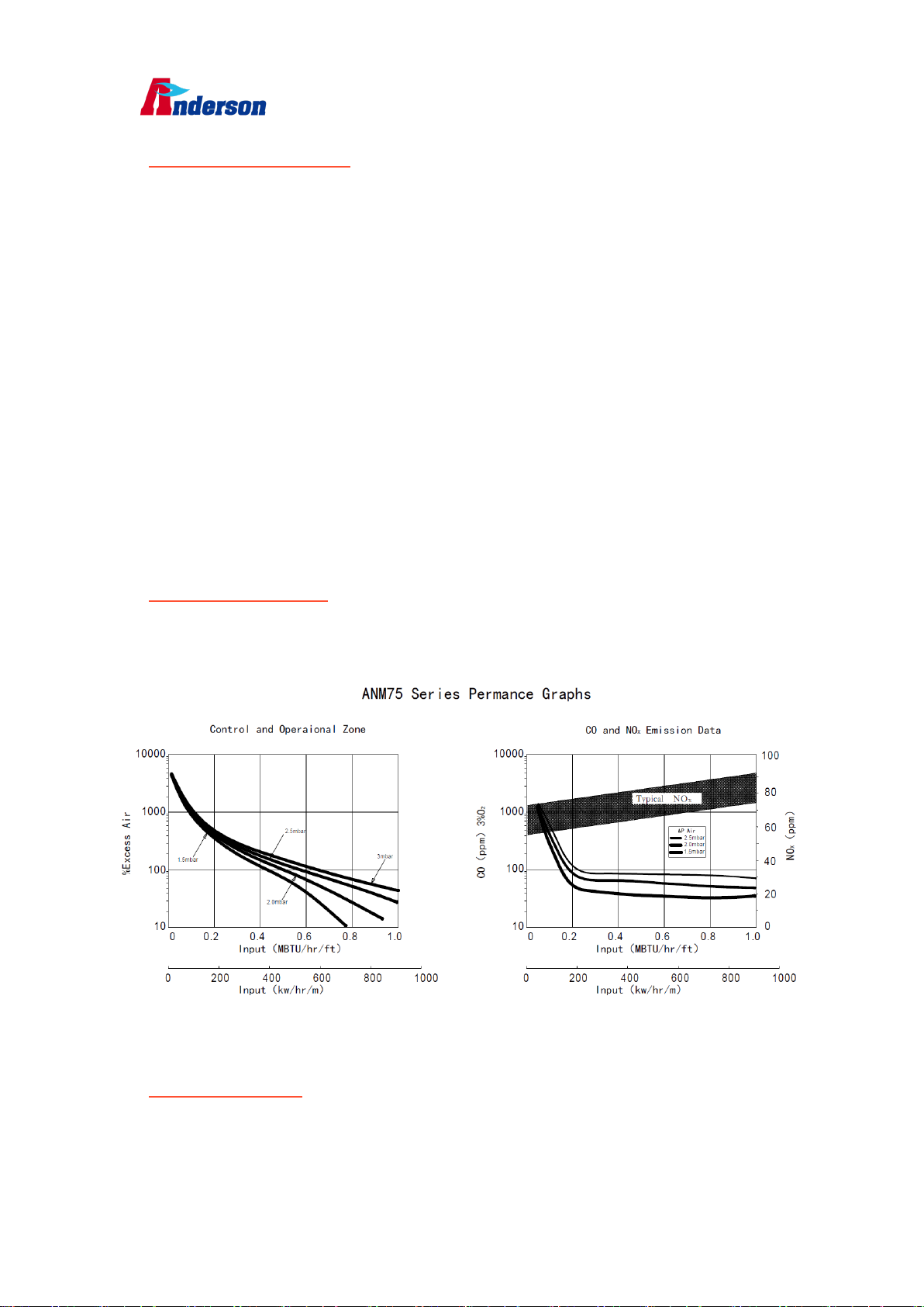
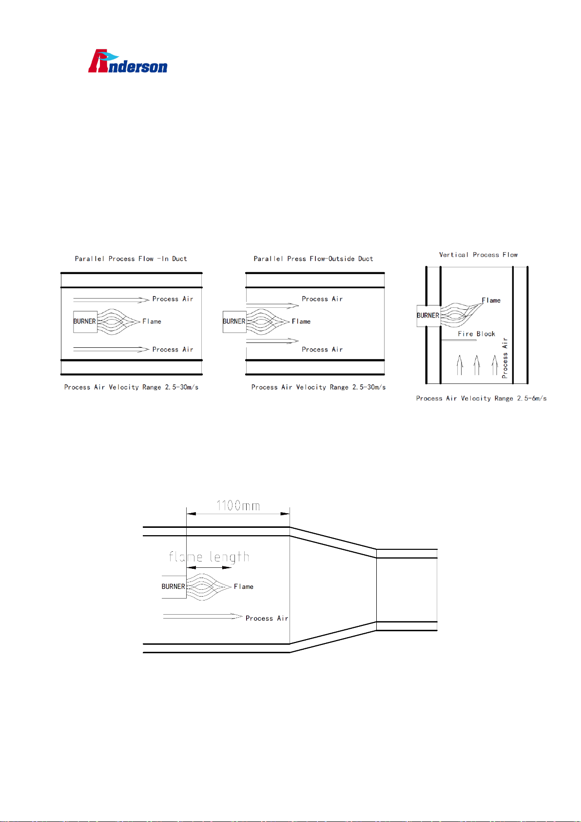
2. Set air flow: Measure the air pressure drop across the burner inlet and duct. Turn
the disc on the blower air inlet until the air pressure is between1.5 to 3.0 mbar. For
a given input, lower air pressure drops will produce a longer flame, and higher
drops will produce a shorter flame with slightly higher CO levels
3. Burner ignition: The gas actuator gets ignition position, the spark plug starts ignition,
at the same time, pilot gas valve open let gas go through the burner to get flame
which is detected by flame or UV scanner to establishes stable pilot flame.
4. Main gas valve open after pilot flame established to set up main flame, all the
ignition process finished.
5. Set high/ low fire gas:Drive the gas actuator to the high fire position, adjust the
outlet of the pressure regulate according to the combustion parameter diagram,
set the gas flow. Then drive the actuator to low fire position, adjust valve opening,
setting gas flow, then get to the high fire position again, adjust gas flow for the
second time, driving again to low fire position to set gas flow to make sure that all
settings are still the same. Do this cycle several times between high and low fire
until satisfied.
6. Determine gas flow: After several cycles of high and low fire positions, check
whether the gas flow at different load positions is similar in same position. It is very
difficult to measure the very low gas pressures experienced at low fire, and it may
be necessary to rely on visual inspection of the flame. This is especially true when
gas turndowns in excess of 20 to 1 are being used. The main intent is to provide a
stable flame with good flame signal that will not cause the chamber temperature

Anderson Thermal Solutions – ANM75 Burner Operation Manual
Anderson Thermal Soluions(Suzhou)Co. ,Ltd.
9
to overshoot.
10.9 Stop Procedure
Do not turn the combustion air blower off until the chamber temperature is below
120°C. This will prevent hot gases from back flowing into the burner and blower
causing damage to the burner.
1. Stop the burner through the burner control system.
2. Run the combustion air blower until the chamber temperature drops below 80°C.
3. Shut off the combustion air blower.
4. Close all manual gas valves to the burner
11. Burner Maintenance
Preventive maintenance is the key to a reliable, safe and efficient combustion system. The
core of any preventive maintenance system is a list of periodic tasks. These are guidelines
only. The customer should make the final determination on maintenance intervals and
tasks to be performed while considering the working environment.
System regular safety audit must be taken out, including gas leakage check no longer than
every half a year. If necessary, the frequency of audit should be increased. Leak detection,
control functions of the equipment must be included in the scope of audit. Only Anderson
technicians or those who are been trained and qualified by Anderson, as well as other
relevant professionals, can maintain the burners. All valves, especially ball valves, must be
slowly open or close when switching in order to prevent pressure shock in pipe.
11.1 Half a year checklist
–Inspect the flame sensing devices for good condition and cleanliness.
–Check for proper air and gas pressures.
–Test all the system alarms for proper response signals.
–Check and clean igniter electrodes.
–Check valve motors and control valves for free, smooth action and adjustment.
–Check for the proper operation of ventilating equipment.
–Test the interlock sequence on all safety equipment. Manually force each interlock to
intentionally fail while at the same time noting if related equipment closes or stops as
specified by the manufacturer. Test the flame safeguard by manually shutting off the
gas to the burner.
–Test the manual gas shut off cocks for proper operation.
–Inspect and clean the combustion air blower rotor. Clean and/or replace the
combustion air blower filter if applicable.
11.2 Yearly checklist
–Leak test the safety shut–off valves and pipe for tightness of closure to make sure no
leakage.
–Test the pressure switch settings by checking the switch movements against pressure
settings and comparing these with the actual impulse pressure.

Anderson Thermal Solutions – ANM75 Burner Operation Manual
Anderson Thermal Soluions(Suzhou)Co. ,Ltd.
10
–Visually check igniter cable and connectors.
–Be sure the burner bodies and air wings, the ignite and the flame sensors are not
damaged or distorted.
12.Troubleshooting Procedures
Problem Possible Cause Solution
Cannot initiate a
start sequence
Air pressure switch has not made
contact
Check air pressure switch adjustment.
Check air filter.
Check blower rotation.
Check outlet pressure from blower.
High gas pressure switch has activated.
Low gas pressure switch has activated
Check incoming gas pressure; adjust if
necessary.
Check pressure switch setting and
operation
Purge cycle not completed.
Check flame safeguard system or
purge timer.
Malfunction of the flame safeguard
system (e.g., flame sensor failure or
electrical noise in the sensor line).
No power to the control unit.
Have a qualified electrician
troubleshoot and correct the problem.
Main power is off.
Be sure the main power to the system
is switched to the “on” position
Start–up sequence
runs but
burner does not light
PILOT IGNITION ONLY
Pilot gas pressure low
Pilot gas cock closed
Pilot solenoid valve close
Gas adjusting valve set too low
Air in the pilot line
Adjust pilot gas pressure
Open pilot gas cock
Check wire for solenoid valve
Increase opening of the valve
Repeat start for several times
PILOT IGNITION OR DIRECT SPARK
Attempting to ignite at inputs greater
than 60%
Reduce start point gas flow.
Verify control circuit.
Weak or non–existent spark.
Verify ignition transformer is a 6,000 –
8,000 Volt transformer

Anderson Thermal Solutions – ANM75 Burner Operation Manual
Anderson Thermal Soluions(Suzhou)Co. ,Ltd.
11
There is no power to the ignition
transformer
Restore the power to the ignition
transformer
The igniter needs cleaning Clean the igniter
The igniter is not correctly grounded to
the burner
Clean the threads on the igniter and
the burner. NOTE: Do not apply
grease to the threads on the igniter
Igniter insulator is broken.
Igniter is grounding out.
Inspect the igniter. Replace if broken.
Not enough gas:
The gas flow into the burner is too low.
Check the start–up settings.
Adjust low fire gas setting if necessary
Gas valve does not open
Check the wiring to the automatic gas
shut–off valve.
Check the output from the flame
safeguard.
Open manual gas cock.
No flame signal
Broken flame rod
Dirty UV scanner lens
Flame rod grounding not good
Replace if necessary
Inspect and clean sensor. Verify that
the flame rod is installed correctly and
is the correct length.
The low fire flame is
weak or unstable
Not enough gas
Incorrect air flow setting
Check start–up settings and adjust to
increase gas flow.
Check air pressure drop across the
burner and adjust.
The burner does not
go to high fire.
Not enough gas pressure out of
main gas regulator.
Gas pressure drops as input is
increased main gas control valve is not
functioning
Adjust pressure regulator so pressure
is provided as stated
Check for clogging of valves and
regulators in gas line.
Pressure regulator may be incorrectly
sized. Replace if necessary

Anderson Thermal Solutions – ANM75 Burner Operation Manual
Anderson Thermal Soluions(Suzhou)Co. ,Ltd.
12
Burner does not
achieve
capacity.
Main gas control valve is not
functioning.
Burner is firing below rated input
Burner gas holes are plugged
Check actuator and linkage
Check gas pressure DP, adjust main
gas pressure regulator as necessary
Inspect gas holes for dirt or lint as
needed
Main flame is uneven
along the length of
the burner.
Air pressure drop/velocity is too low.
Poor air distribution in duct
Air wings are dirty, holes are
clogged
Increase air pressure drop
Check profiling and duct obstructions
Inspect and clean air wings if
necessary
Main flame is yellow
and long at high fire
Gas pressure too high at burner inlet.
Air wings are dirty, holes are clogged.
Air pressure drop/velocity too low.
Check gas pressure against design.
Adjust main gas pressure regulator
Inspect and clean air wings if
necessary.
Open air damper on combustion air
blower
CO emission is too
high.
Burner is run outside specified working
range
Process air velocity exceeds limits
Adjust burner settings
Adjust process air flow, to make
velocity within limits;

Anderson Thermal Solutions – ANM75 Burner Operation Manual
Anderson Thermal Soluions(Suzhou)Co. ,Ltd.
13
13.Appendix
13.1 List of Spare Parts of the Burner
Number
Product No.
Product Name
1
60ZZ0330
Burner Body, 150mm, Cast Iron
2
60ZZ0331
Burner Body, 300mm, Cast Iron
3
60ZZ0332
Burner Body, 450mm, Cast Iron
4
60ZZ0334
Air Wing, 150mm, 310SS
5
60ZZ0335
Air Wing, 90 Degrees, 300mm, 310SS
6
60ZZ0336
Side Plate, 150mm, 304SS
7
60ZZ0337
Side Plate, 300mm, 304SS
8
60ZZ0338
Side Plate, 90 Degrees, 304SS
9
60ZZ0339
Side Plate, 30mm, 304SS
10
60ZZ0341
End Plate, Inlet, 310SS
11
60ZZ0342
Flange, Rc2" Inlet, Cast Iron
12
60ZZ0349
Back Plate, 150mm, 304SS
13
60ZZ0350
Back Plate, 300mm, 304SS
14
60ZZ0351
Back Plate, 63mm, 304SS
15
60ZZ0344
Lifting Plate, 304SS
16
60ZZ0345
Diffuser Plate, 150mm, W=173mm, H=30mm, Carbon Steel
17
60ZZ0346
Diffuser Plate, 300mm, Carbon Steel
18
60ZZ0347
Diffuser Plate, 450mm, Carbon Steel
19
60ZZ0456
Ignition Spark, M14*1.25, OD=3.5mm, Self–Ground, Line Burner

Anderson Thermal Solutions – ANM75 Burner Operation Manual
Anderson Thermal Soluions(Suzhou)Co. ,Ltd.
14
13.2 Spare parts reference figure
60ZZ0330 60ZZ0331 60ZZ0332 60ZZ0334 60ZZ0335
60ZZ0336 60ZZ0337 60ZZ0338 60ZZ0339 60ZZ0341
60ZZ0342 60ZZ0349 60ZZ0350 60ZZ0351 60ZZ0344
60ZZ0345 60ZZ0346 60ZZ0347 60ZZ0456
13.3 Operation Manual Record
Each trained person must verify that he has read and understood the contents of the
operating manual and know how to operate and maintain this series of burners correctly.
Manual Number and
Revision Date Who (Name) Signature

Anderson Thermal Solutions – ANM75 Burner Operation Manual
Anderson Thermal Soluions(Suzhou)Co. ,Ltd.
15
13.4 Half Year Audit Record
Routine audit must be made every 6 months. Please sign the following table.
Function Audit Date Inspector Problem description Next Audit Time
Flame sensor state
air and gas pressure
Alarm signals
igniter electrode
Control motors
Ventilate equipment
Interlock Function
Shut off cock function
Combustion air blower
13.5 Yearly Audit Record
Yearly audit list as follow but not only included
Function Audit Date Inspector Problem description Next Audit Time
Leak test
Pressure switch test
Cable and connectors
Burner bodies and air
wings

Anderson Thermal Solutions – ANM75 Burner Operation Manual
Anderson Thermal Soluions(Suzhou)Co. ,Ltd.
16
Attention:Safety audit is prohibited when burner is running, otherwise, an
accident could be caused!
If you have any questions. Please call us or send an e-mail to get more information
Our telephone no. is +86 (512) 6592 4663
Meanwhile, you can also visit our website www.andtecs.com to get more product
information.
Table of contents
Other Anderson Burner manuals

Anderson
Anderson ANM77 User manual

Anderson
Anderson FFO57 User manual

Anderson
Anderson VFC86 User manual

Anderson
Anderson FFAH21 User manual

Anderson
Anderson Oper-SRB User manual

Anderson
Anderson ANM76 User manual

Anderson
Anderson ANX70 Series User manual

Anderson
Anderson PBA90 User manual

Anderson
Anderson FF050 User manual

Anderson
Anderson PBO92 User manual
Popular Burner manuals by other brands

Riello
Riello RG1RKD Installation, use and maintenance instructions

Unigas
Unigas HTP2000 installation manual

Riello
Riello RS 68/EV O2 BLU Installation, use and maintenance instructions

Modena
Modena CT 7960G User manual book

Beckett
Beckett CF 2500 manual

Bentone
Bentone B 30 A Installation and maintenance instruction