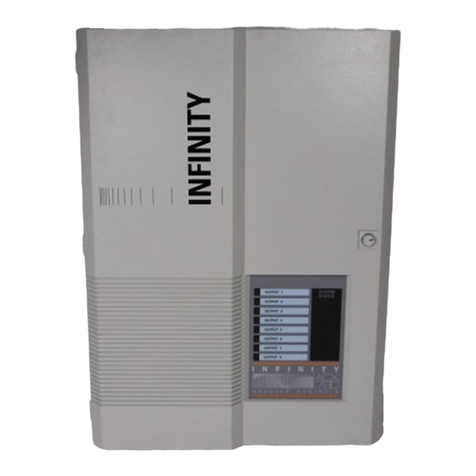
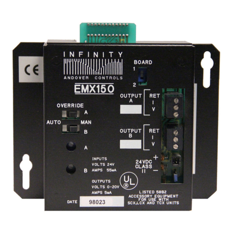
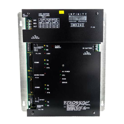
Andover Controls LCX 890 Series User manual

Andover Controls Corporation i
LCX 890 Series Controller
Installation Guide

ii LCX 890 Installation Guide
Version D
Reproduction or distribution forbidden.
Copyright 1997 by Andover Controls.
Subject to change without notice.
Order No. 30-3001-285
Copyright 1997
Andover Controls Corporation
300 Brickstone Square
Andover, Massachusetts 01810
All Rights Reserved.
Published by the Engineering Department at Andover Controls Corporation.
IMPORTANT NOTICE
This product is subject to change without notice. This document does not con-
stitute any warranty, express or implied. Andover Controls Corporation re-
serves the right to alter capabilities, performance, and presentation of this
product at any time.

Andover Controls Corporation iii
Preface
The LCX 890 Series Controller Installation Guide presents instructions
for installing the LCX 890 series controllers on an Infinet. It first pre-
sents site preparation information and then step-by-step installation
instructions.
For information on programming, refer to the Infinity Controller Pro-
grammer’s Guide or the ICS Controller Programmer’s Guide.

iv LCX 890 Installation Guide

Andover Controls Corporation v
Contents
Setting Up an LCX 890 Series Controller
and Infinet
Site/System Setup Requirements .............................................................2
Controller Dimensions and Weight ...............................................3
Power Requirements ......................................................................3
Cable Limitations ...........................................................................3
Lightning Protection ......................................................................4
Building Ground Requirements .....................................................4
Inspecting the Ground ....................................................................5
Environmental Requirements ........................................................6
Output Requirements .....................................................................6
Input Requirements ........................................................................7
Laying Out the Site Setup ............................................................12
Installing LCX 890 Series Controllers ...................................................13
Unpacking ....................................................................................13
Parts Required ..............................................................................13
Mounting ......................................................................................13
Finding the Connection Ports on the LCX 890 ...........................17
Finding the Connection Ports on the LCX 898 ...........................19
Connecting the AC Power ...........................................................21
Selecting the AC Input Voltage ...................................................22
Wiring the Infinet to the LCX 890/898 .......................................23
Wiring the Infinet to the 9000 Controller ....................................24
Locating the Inputs on an LCX 890 ............................................25
Locating the Inputs on an LCX 898 ............................................27
Wiring the Inputs .........................................................................30
Attaching the Output Relays ........................................................34

vi LCX 890 Installation Guide
Locating/Wiring the Momentary Switches ..................................38
Connecting the EMX 170 or SP 100 Module
to the EMX 170 or SP 100 Port ....................................................52
Powering Up the LCX 890 or 898 .........................................................53
Connecting the Battery ................................................................54
Reset Button .................................................................................54
Connecting the Andover Controls Service Tool ..........................54

Andover Controls Corporation vii
Figures
Figure 1. Dimensions to Knockouts for Mounting the LCX 890 ...........15
Figure 2. Dimensions to Knockouts for Mounting the LCX 898 ...........16
Figure 3. Locations of Connection Ports on the LCX 890 ......................18
Figure 4. Locations of Connection Ports on the LCX 898...................... 20
Figure 5. Metal Plate and Screw for Power Supply Wire .......................21
Figure 6. Infinet Cable Wiring ................................................................23
Figure 7. Attaching the Infinet Cable to the 9000 Controller .................24
Figure 8. Location of Inputs, Outputs, and Momentary Switches
on the LCX 890 ....................................................................26
Figure 9. Location of Inputs, Outputs, and Momentary Switches
on the LCX 898.................................................................... 28
Figure 10. Wiring Diagram for a Digital (Switch) Input ........................31
Figure 11. Wiring Diagram for Thermistor Input ...................................32
Figure 12. Wiring Diagram for Voltage Input ........................................32
Figure 13. Wiring Diagram for Current Input .........................................33
Figure 14. Inserting a Relay for an Output on LCX 890 or Right
Side of LCX 898 ..................................................................35
Figure 15. Inserting a Relay for an Output on the Left Side of the
LCX 898 ...............................................................................35
Figure 16. Appearance, Positioning, and Numbering
of Output Relays on LCX 890 ............................................. 36
Figure 17. Appearance, Positioning, and Numbering of Output
Relays on LCX 898.............................................................. 37
Figure 18. Illustration of Wiring Lights to Output Relays ......................38
Figure 19. Location of Momentary Switch and Its
Associated Outputs on the LCX 890 ....................................39
Figure 20. Location of Momentary Switches and Their Associated
Outputs on the LCX 898 ......................................................40

viii LCX 890 Installation Guide
Figure 21. Wiring Diagram for Four-Wire Momentary Switch ..............42
Figure 22. Wiring Diagram for Three-Wire Momentary Switch ............43
Figure 23. Wiring Diagram for Four-Wire Momentary Switch
Controlling Two Adjacent Outputs...................................... 45
Figure 24. Wiring Diagram for Four-Wire Momentary Switch
Controlling Three Adjacent Outputs (LCX 898 Only).........46
Figure 25. Wiring Diagram for Four-Wire Momentary Switch
Controlling Four Adjacent Outputs (LCX 898 Only) ..........47
Figure 26. Wiring Diagram for Occupancy Sensor ................................49
Figure 27. Wiring Diagram for Occupancy Sensor Controlling
Two Adjacent Output............................................................50
Figure 28. Wiring Diagram for Occupancy Sensor Controlling
ON/OFF and HI/LO Outputs ................................................51

Andover Controls Corporation ix
Tables
Table 1. Wire Gauges and Corresponding Maximum Runs for Sensing
Temperatures Up to 70 ×F .....................................................9
Table 2. Wire Gauges and Corresponding Maximum Runs for Sensing
Temperatures Up to 100 ×F................................................... 9
Table 3. Wire Gauges and Corresponding Maximum Runs for Sensing
Temperatures Up to 150 ×F .................................................10
Table 4. Wire Gauges and Corresponding Maximum Runs for Sensing
Temperatures Up to 21 ×C ...................................................10
Table 5. Wire Gauges and Corresponding Maximum Runs for Sensing
Temperatures Up to 38 ×C ...................................................11
Table 6. Wire Gauges and Corresponding Maximum Runs for Sensing
Temperatures Up to 65 ×C ...................................................11
Table 7. Connecting Jumpers for AC Input Voltages .............................22
Table 8. Lengths of Wire Required for Wiring
Adjacent Outputs to the Same Switch ..................................47

x LCX 890 Installation Guide

LCX 890 Installation Guide 1
Setting Up an LCX 890 Series
Controller and Infinet
The LCX 890 family of controllers are lighting controllers, designed to
connect to lights and switches that control those lights. You can have up
to 24 relays for controlling lights, with or without the status feedback op-
tion on an LCX 890 and up to 48 relays on an LCX 898. Each output can
have a momentary switch, such as a motion sensor or other occupancy
sensor, that sends a command to the light.
You may also connect an EMX 170 or SP 100 SmartSensor module to
any LCX 890 series controller.
This manual covers the following:
• Site/System Setup Requirements
• Installing the LCX 890 or 898
• Powering Up the LCX 890 or 898
Warranty Registration
Your warranty is effective for 18 months starting on the date the system
is shipped.
Warning
All wiring and installations must comply with local, state, and national
electrical codes.

2 LCX 890 Installation Guide
Site/System Setup Requirements
Before you proceed to install thesystem, you should map out where you
plan to installeach controller, terminal/workstation, and modem. When
planning the sites, be aware of any electrical interference that may oc-
cur. You also need to be aware of cabinet dimensions, power
requirements, cable limitations, and environmental requirements.
Note
This equipment has been tested and found to comply with the limits for
a Class A digital device, pursuant to Part 15 of the FCC Rules. These
limits are designed to provide reasonable protection against harmful
interference when the equipment is operated in a commercial
environment. This equipment generates, uses, and can radiate radio
frequency energy and, if not installed and used in accordance with the
instructions in this manual, may cause harmful interference to radio
communications. Operation of this equipment in a residential area is
likely to cause harmful interference in which case the user will be
required to correct the interference at his own expense.
Note
This digital apparatus does not exceed the Class A limits for radio noise
emissions from digital apparatus set out in the Radio Interference
Regulations of the Canadian Department of Communications.
Avis
Le présent appareil numérique n’émet pas de bruits radioélectriques
dépassant les limites applicables aux appareils numériques de la class A
prescrites dans le Règlement sur le brouillage radioélectrique édicté par
le ministère des Communications du Canada.

LCX 890 Installation Guide 3
Controller Dimensions and Weight
Each LCX 890 is 34.9H ×18.3W ×4.67D in. (886.46H ×464.82W ×
118.62D mm) and weighs 38 lbs (14.17 kg) without relays.
Each LCX 898 is 38.8H ×27.35W ×4.67D in. (985.52H ×694.69W ×
118.62D mm) and weighs 42 lbs (23.49 kg) without relays.
Power Requirements
Caution
Any LCX 890 should receive power from its own independent,
unswitched circuit.
You can select an AC line voltage of 115 V, 230 V, or 277 V. You re-
ceive the controller set to 115 V. Instructions for selecting the AC line
voltage you want are included with the installation.
Voltages you can select are as follows (each uses a 2 A slow blow fuse):
• 115 VAC +/– 10% 50/60 Hz
• 230 VAC +/– 10% 50/60 Hz
• 277 VAC +/– 10% 50/60 Hz
Each LCX 890 series controller consumes 115 VA of power.
Cable Limitations
The maximum cable length for all buses is 4,000 ft (1219 m) at 19,200
baud (up to 32 Infinet controllers). You can extend buses beyond
4,000 ft (1219 m) or put more than 32 Infinet controllers on less than
4,000 ft (1219 m) by using the InfiLink 200 amplification module.

4 LCX 890 Installation Guide
Note
You must use shielded cables for Infinet to ensure compliance with the
Class A FCC limits and to provide reliable communications.
Cables that form Infinet are 24-gauge (.22 to .38 mm2), single-twisted-
pair, tinned, shielded copper wire. Use the following cables1or their
equivalents:
• Brand Rex # H 9002 (single-pair)
• Anixter # 9J2401021 (single-pair plenum cable)
The cable should have a nominal impedance of 100 Ωand a nominal ve-
locity of propagation of 78%.
Capacitance of Infinet cable should be nominal, below 12.5 pF/ft (41 pF/
m) between conductors and below 22 pF/ft (72 pF/m) between the con-
ductor connected to ground and the next conductor.
Lightning Protection
The LCX 898 has a 2 A,500 V fuse and 1500 V transformer that isolates
the unit.
The unit has 1500 V .01 µF spark gap caps from HOT and NEUTRAL
to chassis ground. These help increase protection against power surges.
Lightning arrestors are required at each point where a bus cable enters
or exits a building. Use the following arrestor:
Two pair gas tube arrestor, Andover Controls # 01-2100-299.
1. You can also use any cables you may already have in place for ACNET or LBUS.

LCX 890 Installation Guide 5
Building Ground Requirements
Warning
Be sure that all hardware from Andover Controls Corporation is
grounded to true earth ground. This kind of ground protects the
equipment from transients and other power surges in the area.
We cannot guarantee that the controller system will operate as
documented unless you properly ground all controllers.
Warning
Be sure to have your grounds inspected before you begin the
installation process to be sure your municipality follows the National
Electrical Code. Many municipalities do not and often have
substandard electrical grounds.
An example of a substandard ground is a galvanized steel cold water
pipe. As the pipe corrodes, it does not act as a true ground. The corro-
sion acts as an insulator, raising the potential of the pipe with respect to
the ground.
When lightning strikes in the area of the installation, it drastically
changes the potential of the earth. Since properly grounded Andover
Controls units respond to changes in potential more rapidly than poorly
grounded electrical systems, a poorly grounded building tries to reach
ground through the Andover Controls system. The surge of current can
destroy electronic components on the controller board.
Surges of much lower potential than lightningalso impact the reliability
of Andover Controls equipment.

6 LCX 890 Installation Guide
Inspecting the Ground
You can check your ground as follows:
1. Check your ground byfirst inspecting the building power distribution
panel for earth ground termination. If the ground termination is any
of the following, it is not adequate and must be corrected:
• Does not exist.
• Is connected to a corroded or galvanized pipe.
• Is connected using a small gauge wire (less than 14 AWG
or 2.5 mm2).
2. Be sure your Andover Controls cabinet is connected to the ground
with a copper conductor that terminates at the distribution panel.
Environmental Requirements
All LCX 890 controllers operate in rooms with temperatures ranging
from 32 to 120°F and with humidity between 10 and 95%, noncondens-
ing. If you connect a SmartSensor, the temperature can range from 32
to 104°F.
The controller is in an Underwriter Laboratories approved enclosure.
Do not remove the controller from the enclosure provided.
Output Requirements
The outputs on LCX 890 and 898 controllers are digital and can be
wired to control lighting. To each output you attach either relays that
give status feedback (Andover Controls Part # 01-0100-300) or relays
that do not give status feedback (Andover Controls Part # 01-0100-
299).
All outputs are programmable. You may also wire a momentary switch
to the light. This switch can be a motion detector or other occupancy
sensor. When the motion detector or other sensor determines light is re-
quired, it sends a signal to the output relay. The relay mechanically

LCX 890 Installation Guide 7
latches itself ON. The relay remains ON until you either set it to OFF
from the software or the momentary switch sets it to off.
The status of the light is available in the software if you use relays that
give feedback. In addition, the status light adjacent to each output lights
up if the output is ON.
Each relay is rated for any of the following lighting loads:
Note
Andover Controls does not recommend switching DC loads. Switching
DC loads can damage the relay.
• 20 A with a Tungsten filament at 125 VAC
• 20 A with a Ballast at 277 VAC
• 20 A with Resistive element at 277 VAC
The motor load is 1/2 horsepower at 110 to 125 VAC or 1/2 horsepower
at 220 to 227 VAC.
Andover Controls relays are prewired for the LCX 890 series of control-
lers and plug in to the 5-pin connector adjacent to each output.
LCX 898 outputs have 4,000 V noise immunity from IEC E801-4 and
ANSI/IEEE C 62.41 5 ns/50 ns EFT test waveforms.
Input Requirements
Caution
Andover Controls inputs are designed to be used with two-wire devices
and do not provide sufficient power to operate sensors requiring an
external power supply.
The LCX 890 controllers each have two types of inputs, digital and uni-
versal. The paragraphs that follow give the requirements of each type of
input.

8 LCX 890 Installation Guide
Digital Inputs
The first 16 inputs on all LCX 890 controllers are digital, for switches.
The controller can read the settings of these switches.
All digital inputs have an input impedance of 220KΩreferenced to
5.000 V.
Universal Inputs
The last eight inputs (not including the EMX 170 port) on the LCX 890
or LCX 898 (17 through 24) are universal. Thelast eight inputs onthe are
universal.Universalinputsareforanytypeofsensor,suchasthermistors,
motion sensors, and switches.
Below are the requirements of each universal input:
• Voltage Range—0 to 5.115 V
• Resolution—0.005 V
• Accuracy—+/–0.015 V
• Maximum Pulse Frequency—5 Hz at a duty cycle of 50% with a
minimum pulse width of 100 ms
• Input Impedance—10KΩreferenced to 5.120 V
• Filtering—Corner Frequency at 15 Hz, –20 db/decade
• Over-Voltage Protection—24 VAC RMS or 24 VDC indefinitely on
any single channel; +/–1500 V transient for 50 µs on all channels
• Calibration—Permanent (factory)
EMX 170 Inputs
If you have an EMX 170 on the EMX 170 port, it is an additional input,
numbered 25.

LCX 890 Installation Guide 9
Special Factors for Thermistors
You could connect a thermistor to one of the analog inputs. To keep
thermistor errors minimal, lay out your site so you can limit the length
of wire runs to the maximum for the gauge wire you select.
Table 1 shows the maximum runs for wires of various gauges to keep
errors within .5°F, .25°F, and .10°F when sensing temperatures up to
70°F.
Table 1. Wire Gauges and Corresponding Maximum Runs
for Sensing Temperatures Up to 70
°
F
Table 2 shows the maximum runs for wires of various gauges to keep
errors minimal when sensing temperatures up to 100°F.
Gauge 1/2°F Error
#20 6600 ft
#14 26,700 ft
#16 16,800 ft
#18 10,500 ft
1/4°F Error
3300 ft
13,300 ft
8400 ft
5200 ft
1/10°F Error
1300 ft
5300 ft
3300 ft
2100 ft
#22 4100 ft 2000 ft 800 ft

10 LCX 890 Installation Guide
Table 2. Wire Gauges and Corresponding Maximum Runs
for Sensing Temperatures Up to 100
°
F
Table 3 shows the maximum runs for wires of various gauges to keep
errors minimal when sensing temperatures up to 150°F.
Table 3. Wire Gauges and Corresponding Maximum Runs
for Sensing Temperatures Up to 150
°
F
Table 4 shows the maximum runs for wires of various gauges to keep
errors within .28°C, .14°C, and .06°C when sensing temperatures up
to 21°C.
Table 4. Wire Gauges and Corresponding Maximum Runs
for Sensing Temperatures Up to 21
°
C
Gauge .28°C Error .14°C Error .06°C Error
2.5 mm28150 m 4000 m 1600 m
Gauge 1/2°F Error
#20 3100 ft
#14 12,700 ft
#16 7900 ft
#18 5000 ft
1/4°F Error
1500 ft
6300 ft
3900 ft
2500 ft
1/10°F Error
600 ft
2500 ft
1500 ft
1000 ft
#22 1900 ft 900 ft 300 ft
Gauge 1/2°F Error
#20 1000 ft
#14 4100 ft
#16 2600 ft
#18 1600 ft
1/4°F Error
500 ft
2000 ft
1300 ft
800 ft
1/10°F Error
200 ft
800 ft
500 ft
300 ft
#22 650 ft 300 ft 130 ft
This manual suits for next models
2
Table of contents
Other Andover Controls Controllers manuals

Andover Controls
Andover Controls ACC EMX 150 User manual

Andover Controls
Andover Controls Infinity User manual

Andover Controls
Andover Controls SCX 920 User manual

Andover Controls
Andover Controls ACX 780 User manual

Andover Controls
Andover Controls CMX 240 Series User manual

Andover Controls
Andover Controls CMX 220 User manual

Andover Controls
Andover Controls DCX 250 User manual