9 1-13-2022
Tips for drilling: Keep drill bit straight and perpendicular to the tube surface.
Make sure not to push to hard and bend the tube surface.
Ensure all chips and burrs are removed from the inside and outside of the tube after drilling.
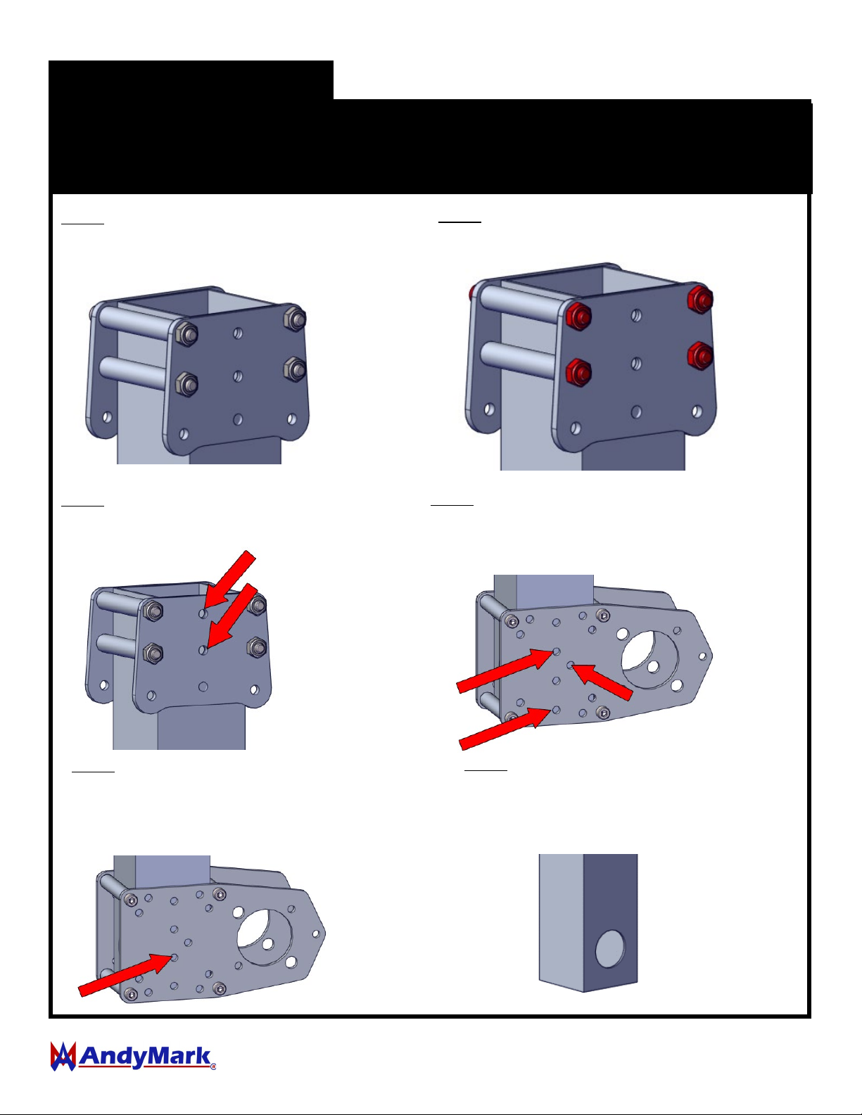
Step 1: Align the flat edge of the
bearing plate with the edge of the
Box Tube.
Step 2: Tighten screws to secure
assembly.
Step 3: Use a #7 .201" drill bit and
drill two holes on both sides.
Step 4a: Move the bearing plate assembly to the other
end of tube and other face 90 degrees opposed to the
faces with the holes drilled in the previous step. Use a
#7 .201" drill bit and drill three holes on both sides.
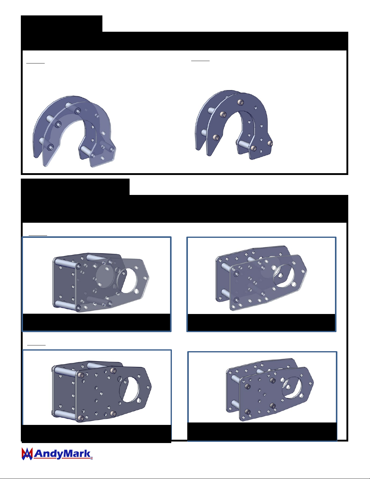
For 2-Stage Climbers drill the following additional holes in the 1.5” Box Tubes
Step 4b: Align the winch plate
assembly to the other end of the tube.
Use a #7 .201" drill bit and drill three
holes on both sides. Ensure the offset
hole aligns across the tube.
For 1-Stage Climbers drill the following additional holes in the 1.5” Box Tubes
Step 5b: Move the winch plate
assembly to the face 90 degrees
opposed to the faces with the holes
drilled in the previous step. Use a
#7 .201” drill bit and drill in the
center hole on ONE side.
Step 5c: Using a step drill bit, open
up the hole in the tube to
approximately 1.125” in diameter.
The rope will pass through this
hole so make sure the edges are
deburred and smooth.