TPC ERN Series User manual
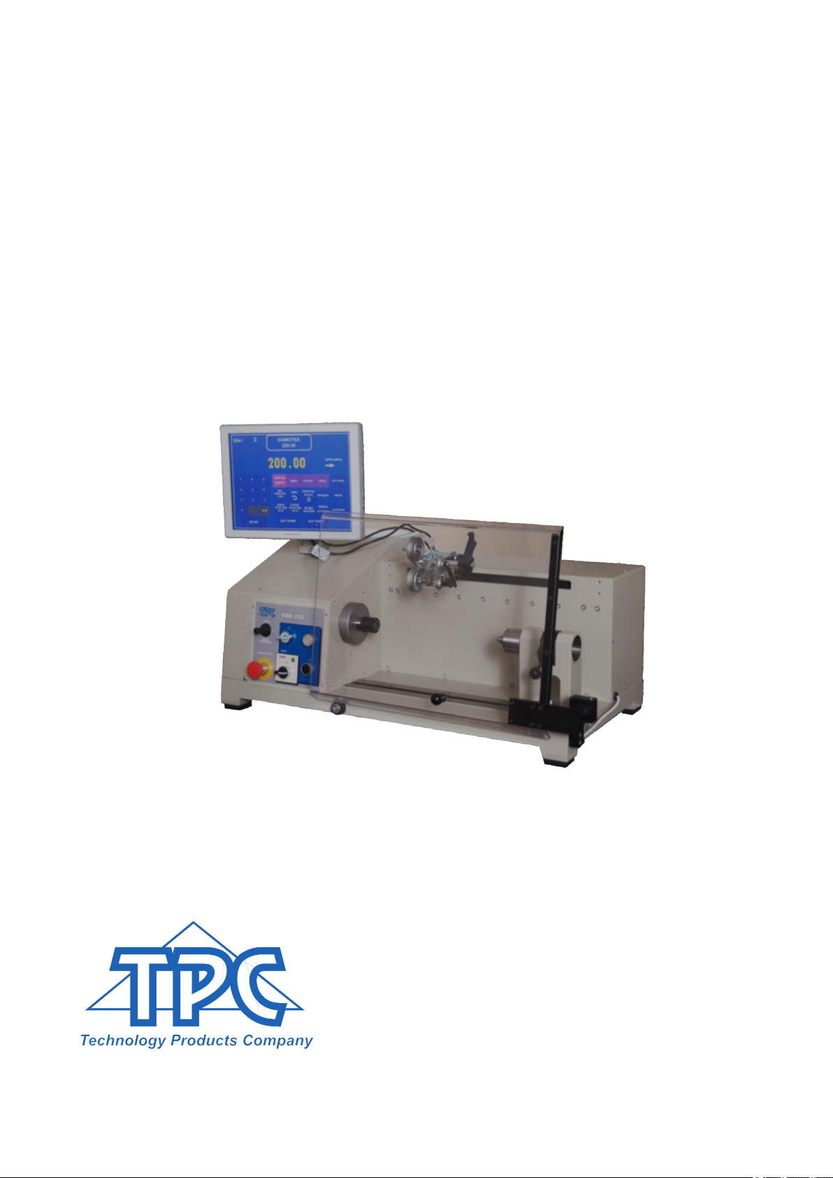
COIL WINDING MACHINE ERN T-VERSION
OPERATING INSTRUCTIONS
ERN 22, 32, 32S, 42, 52
TPC s.r.o
Pálenica 53/79
03301 Liptovský Hrádok
SLOVAKIA
Tel.: +421-44-5221366
Fax: +421-44-5222088
E-mail: [email protected]
www.tpc.sk
Version: 1.3
Date: December 21, 2018

1. Introduction
1.1 Characteristic features
2. Technical data
2.1 Climatic conditions
3. Description of machine
3.1 Description of controls
3.2 Description PC display
4. Installation and preparation of working equipment
4.1 Connection to the power
5. Winding operation
5.1 Switching the machine ON and gear setting
5.2 Backup of winding data in case of an electricity drop
5.3 Winding and programming window
5.4 Explanation of concepts STANDSTILL, START, STOP
5.5 Winding programme selection
5.6 Start and Stop of winding cycle
5.7 Foot pedal
5.8 Protection shield
5.9 Winding corrections
5.9.1 Spindle reference position setting
5.9.2 Wire guide relative position setting
5.9.3 Number of turns correction
5.9.4 Total counter
5.9.5 Wire guide correction
5.9.6 Wire guide direction change
5.9.7 Abort step
5.9.8 Back winding
5.9.9 Deceleration ramp for the STOP - button
5.9.10 Spindle zero position
6. Joystick
7. Programming
7.1 Basis of programming
7.2 Step parameters programming
7.2.1 Basic step types
7.2.2 Wire guide shift
7.2.3 Winding step
7.2.4 Wire guide jump
7.2.5 Delay
7.3 Display and assignment of the layer
7.4 Programming corrections
7.4.1 Insert empty step
7.4.2 Delete step
7.4.3 Copy step
7.4.4 Global change
7.4.5 Coordinate offset
1
1
2
2
2
3
6
7
7
8
8
10
11
11
12
12
13
14
15
15
16
17
17
18
18
19
19
20
20
21
23
24
25
25
25
27
31
32
33
34
34
35
35
36
37

7.5 Special functions
7.5.1 Layer-stop
7.5.2 Layer end
7.5.3 Warnings
7.5.4 Automatic correction
7.5.5 Automatic switch to manual regime
7.5.6 Trapezoidal winding
7.6 Auxiliary inputs and outputs
7.6.1 Window for inputs and outputs
7.6.2 Digital inputs programming
7.6.3 Digital outputs programming
8. Steps list
9. Programme saving and opening
9.1 Programme opening
9.2 Programme saving
9.3 Programme copy
10. Menu
10.1 Programme locking
10.2 Error messages
10.3 Model selection
10.4 Display language
10.5 Winding machine number
10.6 Access PIN code setting
10.7 Zero spindle position mode
11. Firmware and upgrade
11.1 Upgrade of the application programme
11.2 Upgrade of the control board
12. Creation and modification of the operator list
13. Production log settings
13.1 Production log
13.2 Terminal mode
14. Software GRAPHIC
15. Gear change
16. Package contents
17. Fuse change
18. Maintenance
19. Warranty period and service
38
38
39
39
40
42
43
44
44
45
45
47
51
51
53
54
55
55
56
57
58
58
58
59
60
60
60
61
62
62
63
64
65
66
66
66
66

1. INTRODUCTION
Bench-type universal coil winding machine ERN is designed for winding the coils,
transformers, chokes, resistors etc with wire up to diameter of - see technical data.
1.1 Characteristic features:
- 15" industrial capacitive touch screen for data display and programming
- wide range of application for winding simple or complicated coils, multi-chamber coils,
trapezoidal or asymetric windings
- AC servo, that is used like a spindle drive assures excellent dynamical parameters,
constant torque and accurate positioning
- wire guide on ball bearings with a separate stepping motor
- accurate reversible turn counting
- microprocessor-controlled winding cycle without time waste
- wide programming options
- special functions Layer-stop, Automatic guide correction, Manual regime
- 4 programmable digital outputs
- 4 programmable digital inputs
- 40 GB programme store
-connection : 2x USB 2.0
1x USB 3.0
1x LAN
1 / ERN T / V 1.3

2. TECHNICAL DATA
Wire diameter (mm):
Pitch range (mm/rev):
Winding width (mm):
Winding speed / torque [rpm/Nm]:
Accuracy of spindle stop [rev]:
Spindle position pre-set [rev]:
Wire guide position pre-set [mm]:
Max.speed of wire guide - shift [mm/s]:
- winding
Acceleration/deceleration:
Max.coil diameter [mm]:
Distance between centres [mm]:
Dimensions (mm):
Weight [kg]:
Power supply [V/Hz]:
Power consumption [kVA]:
Noise [dB]:
3. DESCRIPTION OF MACHINE
Coil winding machine ERN consists of the following parts:
- controller containing control electronics
- industrial PC with 15" touch screen
- drive unit containing servomotor with gears, pitch control unit with stepping motor,
power electronics and control elements
- base plate
- protection shield
- support with spool holders and dereelers (optional accessories)
- tailstock (optional accessories)
- wire guides (optional accessories)
Winding cycle (linear acceleration, max.speed, linear deceleration and stop) is running automatically
after pressing the START-button. Deceleration is controlled by microprocessor to ensure
accurate stopping and spindle positioning.
rpm MAX.SPEED
NUMBER OF TURNS
DECELERATION
LINEAR ACCELER.
2.1 Climatic conditions
Machine is designed for normal workshop conditions with relative air moisture
70% and temperature in the range of +15 up to +30 C.
ERN22
0,02 - 1,7
0,008 - 40
0,01 - 210
12000 / 0,7
6000 / 1,5
3000 / 3
0,01
0,01
0,01
100
75
table
180
250
780 x 420
85
230 / 50-60
1
74
ERN32
0,02 - 2,5
0,008 - 40
0,01 - 300
6000 / 1,5
1500 / 6
750 / 12
0,01
0,01
0,01
100
75
table
250
340
870 x 460
120
230 / 50-60
1,2
74
ERN32S
0,02 - 3,0
0,008 - 40
0,01 - 300
4000 / 3,5
1000 / 15
500 / 30
0,01
0,01
0,01
100
75
table
250
340
870 x 460
120
3x 400/50-60
1,5
74
ERN42
0,02 - 5,0
0,008 - 40
0,01 - 300
4000 / 3,5
1000 / 15
500 / 30
0,01
0,01
0,01
100
75
table
450
330
910 x 530
140
3x 400/50-60
1,5
74
ERN52
0,02 - 5,0
0,008 - 40
0,01 - 450
4000 / 3,5
1000 / 15
500 / 30
0,01
0,01
0.01
100
75
table
450
650
1235 x 530
180
3x 400/50-60
1,5
74
2 / ERN T / V 1.3

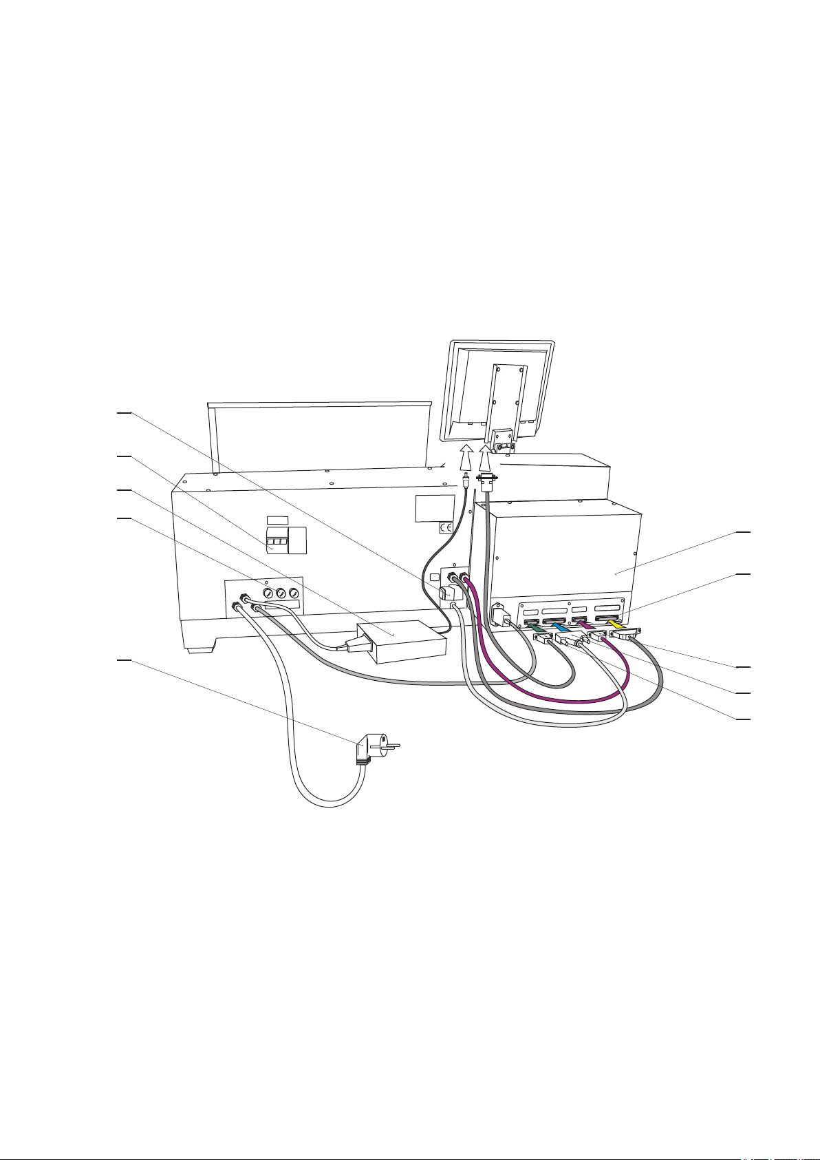
3.1 Description of controls
1 - POWER ON / OFF switch
2 - EMERGENCY STOP - disconnects power in emergency
3 - POWER ON indicator
4 - START button - starts the winding cycle
5 - STOP button - interrupts the winding cycle
6 - BRAKE ON / OFF - switches on/off the electromagnetic brake
7 - JOYSTICK
8 - Fixing screws
9 - Gear cover with timing belt
10 - Industrial PC
11 - Controller
12 - Serial interface between Controller and PC
13 - Connectors for joystick, inputs and outputs
14 - Power plug
15 - AC circuit breaker (only for ERN 32S,42,52)
16 - Fuses
17 - PC power supply
18 - CAN-BUS cable
19 - Control unit cable
20 - Connector for foot pedal
3 / ERN T / V 1.3

4 / ERN T / V 1.3
6
10
3
7
8
16
2 1 5
11
15
9
ENTER
ERN-22
GEAR
6000
REMEMBER
POSITION
OF
4
I
0
EMERGENCY STOP
BRAKE
POWER
WINDING
CORRECTIONS
STEP +
15
16
13
10
18
19
12
17
20
14
5 / ERN T / V 1.3
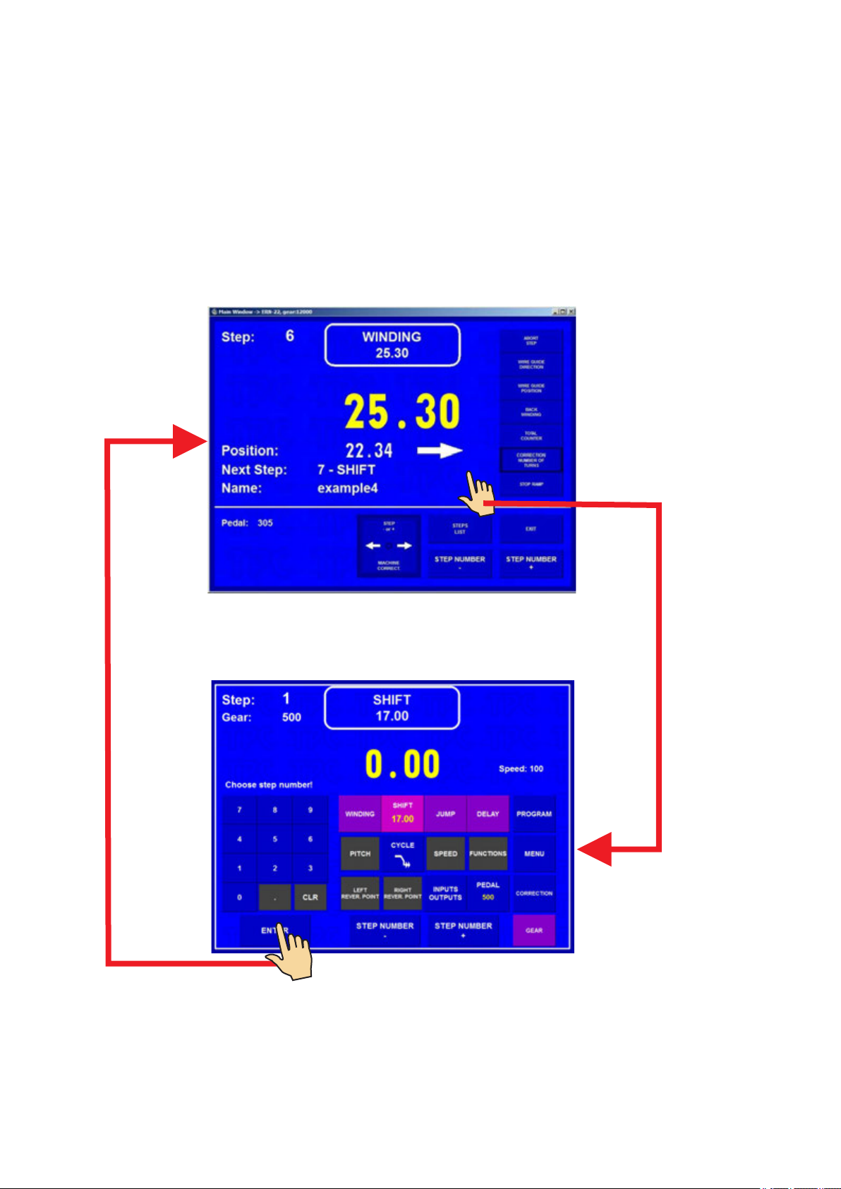
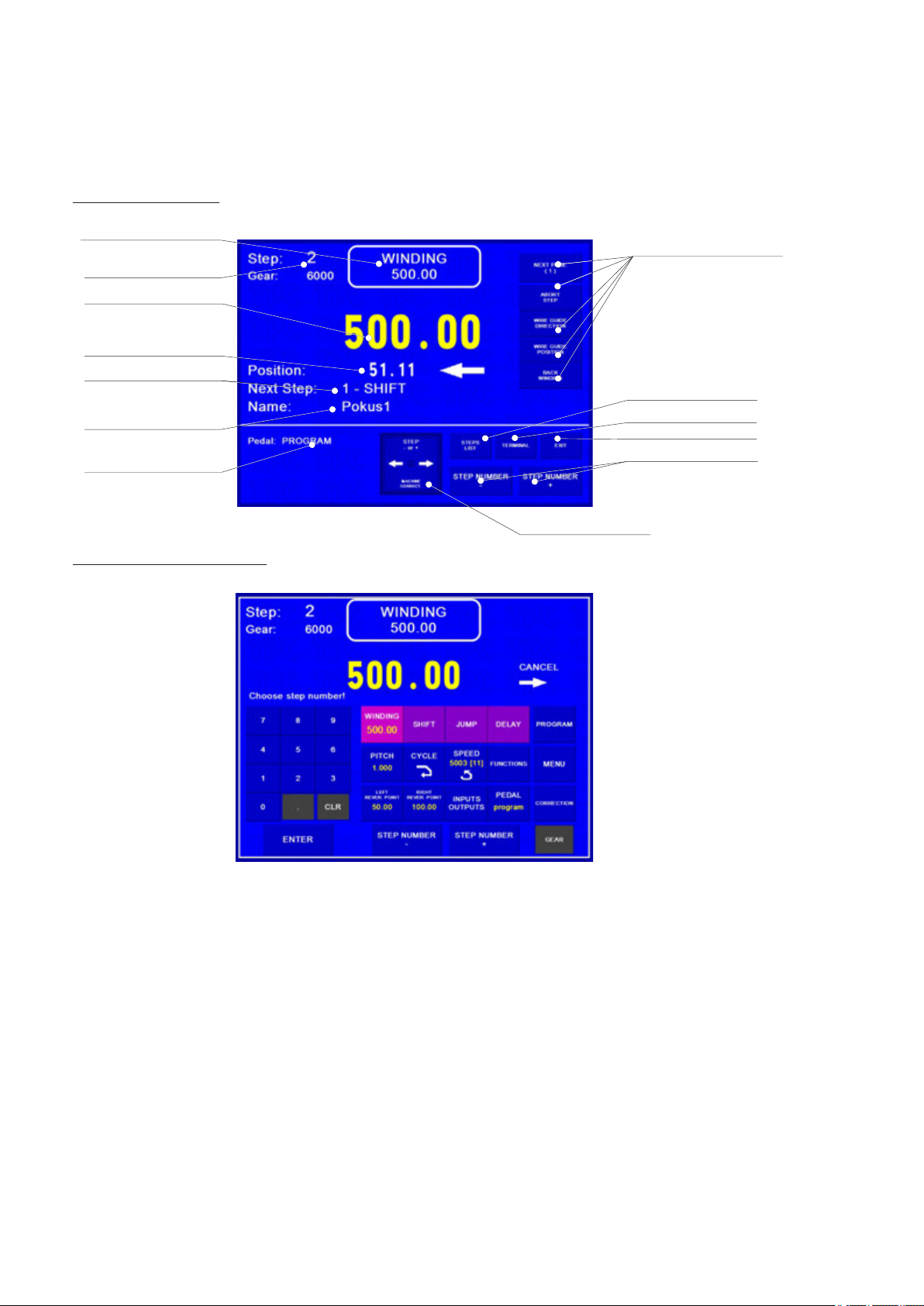
3.2 Description of PC display
Display provides two basic views for standard information during winding:
Winding window and Programming window.
Switching from Winding to Programming window it is necessary to touch central display place.
Switching back - touch ENTER button.
6 / ERN T / V 1.3
Winding window
Programming window
In order to work with a PC we can use the supplied mouse, which we plug into the USB port .
Some advanced computer operations can be performed only with the mouse and keyboard.

4. INSTALLATION AND PREPARATION OF WORKING EQUIPMENT
The machine should be operated by a skilled person who is acquainted with operating manual
and safety formulars. The training is provided by manufacturer or qualified person.
The machine is delivered partly disassembled for easier packing and transport.
Before you switch the machine ON for the first time, assemble it as follows:
a) Mount the controller and display on the drive unit. Connect cables in accordance with the picture - page 5
b) Check and fasten the fuse cartridges on the back panel of the drive unit
c) Assemble support with spool holders and dereelers
d) Connect the foot pedal to the connector (20)
Assembly is now complete and the machine is ready for use.
4.1 Connection to the power
The machine must be powered:
ERN 22,32 - by N/PE 230V/50 Hz AC with tolerance + - 5% and max. power consumption 1,2 k VA.
ERN 32S,42,52 - by 3N/PE 400V/50 Hz AC , tolerance + - 5%, max.power consumption 1,5 kVA.
Before plugging in the connection cable make sure that electric power is in accordance with conforms
to technical requirements. Only professional staff who are qualified in electrical engineering are allowed
to install the power connection to the machine.
Since the leakage current to PE is more than 3,5 mA, in compliance with IEC 61800-5-1
the PE connection must be doubled.
USE THE PE TERMINAL ON THE BACK OF THE MACHINE FOR THIS PARALLER PE CONNECTION.
If a residual current protective device is used, we recommend that each winding machine
be protected individually using a 30 mA RCD.
There is no guarantee for damages caused by wrong or out of range connection
to the power supply.
7 / ERN T / V 1.3

8 / ERN T / V 1.3
After pressing "OPERATOR" it is possible to choose operator name and continue by pressing START.
This window appears only if you choose operator login (see chap. 13.)
OPERATOR
LOGIN
20.4.2011 8:30
OPERATOR : operator 1
OPERATOR
1
4
7
0
START
2
5
8
3
6
9
5. WINDING OPERATION
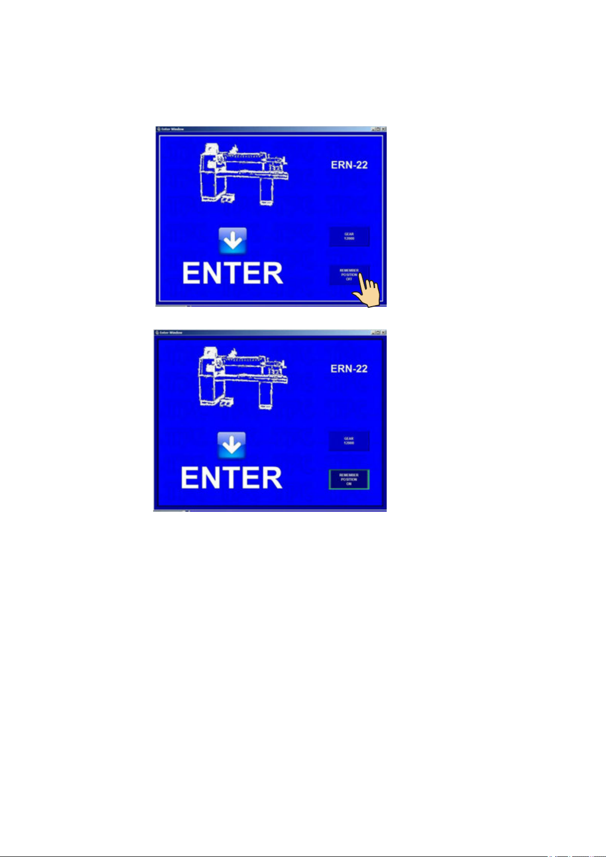
5.1 Switching the machine on and gear setting
After switching on (1) the start window appears
Display provides information about the type of machine the controller is set for.
In this window the set gear can be changed. This must be in ABSOLUTE ACCORDANCE with how
the mechanical gear is set.
28.5. 2015 11:45

After pressing ENTER the initial setup is complete. This means that the wire guide is shifted
to left home (zero) position - zero number of turns, step 0 and the last programme is set.
9 / ERN T / V 1.3
1
2
The gear change requires the use of password - Master code (listed in the warranty card)
as a confirmation that the change is done by an authorized person.
5.2 Backup of winding data in case of an electricity drop
In this window the initial setting of the machine (wire guide position, number of turns and step)
can be activated.
After the activation of this function (MEM.POS.ON) will be updated with values as they were
before the electricity drop.
IN ORDER TO USE THIS FUNCTION THE MACHINE MUST BE EQUIPPED WITH
THE UNINTERRUPTIBLE POWER SUPPLY UNIT (UPS) AND THE REPORT OF
ELECTRICITY DROP (relay for POWER) MUST BE INSTALLED.
IF THE MACHINE IS NOT EQUIPPED WITH THIS, THE INITIAL SETTINGS WILL BE SET TO
ZERO VALUES.
10 / ERN T / V 1.3
5.3 Winding and programming window
There are two basic windows.
Winding window - provides actual information about the winding process
Programming window - displays the view of programmed step parameters
Winding is possible only in these two windows and STEPS LIST window .
If any other window is opened, the cycle start is blocked.
5.4 Explanation of concepts STANDSTILL, START, STOP
STANDSTILL: State after switching on the machine and pressing ENTER, or after a step
finished. Starting from this state will shift the programme one step forward.
Eg.: If we are in the step 0, after pressing START, step 1 will be running.
START: Active run of some step type (winding, shift, jump and pause).
STOP: State after pressing the STOP-button (cycle interruption).
Pressing the START-button again will reactivate the interrupted cycle. There is no step shifting.
11 / ERN T / V 1.3
Wire guide position
and direction
Actual state
Step
Number of turns
Next step
Coil name
Pedal speed
Winding corrections
Steps list
Terminal
Exit
Step change
Joystick
12 / ERN T / V 1.3
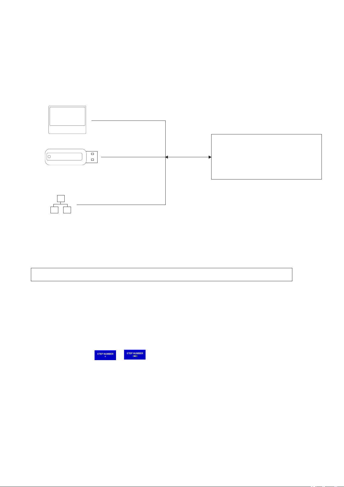
5.5 Winding programme selection
The winding programme we are currently using with (winding or programme creation can be performed)
is called ACTUAL PROGRAMME. Actual programme is located in so-called working part of memory.
Desired winding programme can be loaded to the working part of memory either from PC memory,
USB flash drive or a LAN network.
USB
Proceeding with programme selection: see section 9.
Working part of memory
ACTUAL PROGRAMME
NONVOLATILE MEMORY
Data store in the working part of memory will remain there even if power is disconnected!
PC SSD disc
PART D
LAN
5.6 Start and Stop of winding cycle (programme)
Winding cycle is initiated by pressing START-button (4), or foot pedal.
It is possible to start programme from each step. Required step is set up
by the touch buttons , numeric keyboard or joystick.
STOP-button (5) interrupts the winding cycle. It is the priority button, which means, that the cycle
interruption at incorrect time (while deceleration), may cause inaccurate stopping and
positioning of the spindle.
Cycle interruption at the step "Winding" allows almost all corrections and adjustments.
-

5.7 Foot pedal
Winding machine may be equipped with the following types of foot pedal:
Double foot pedal controls START, BRAKE RELEASE
- left pedal releases the spindle brake
- right pedal works in parallel with the START-button
Double foot pedal controls SPEED, BRAKE RELEASE
- left pedal releases the spindle brake
- right foot pedal controls spindle speed depending how hard the pedal is pressed.
Maximum speed, acceleration and deceleration ramp can be set up by PEDAL button.
Speed set up in this way is applicable only for the current programme. It is independent of the
speed programmed in a specific programme step. Eg.: maximum speed set up by START
pedal may be differ to maximum speed set up by START button.
There is a time delay 0,5 sec between repeated presses for safety work to prevent
unintended start of the next step.
13 / ERN T / V 1.3
Acceleration and deceleration ramp values are always taken from window PEDAL SETUP.
CODE
1
2
3
4
5
6
7
8
ACC.TIME DEC.TIME
1,0
1,6
2,4
3,0
4,0
5,0
6,0
8,0
0,5
0,8
1,2
1,5
2,0
2,5
3,0
4,0
( sec ) ( sec )
Accel. and dec. ramp for pedal
21
3
14 / ERN T / V 1.3
5.8 Protection shield
Protection shield may be programmed as:
CLOSED
It is possible for winding to only work if the protection shield is closed.
If the shield is opened, the cycle is interrupted.
OPENED
It is possible for winding to work whilst the protection shield is open but in such case the spindle speed
will be automatically limited to only work up to pre-set safety values.
When the shield is closed during the winding, the cycle continues with the programmed speed values.
If we require the same maximum pedal speed as speed programmed in the current programme step,
we need to press the PARAMETERS FROM PROGRAM button.
Max. pedal speed is controlled by values programmed in individual programme steps.
Winding cycle start continuity
This option is utilized during winding start. Wire application and winding of the first turns is done by
pedal and then by pressing START button (4) cycle continues. Winding cycle can continue seamlesly
without interruption.
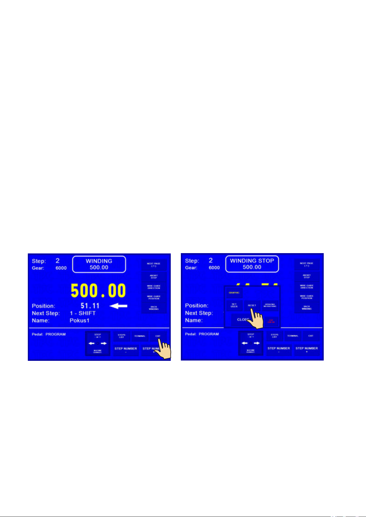
5.9 Winding corrections
Program corrections and adjustments are allowed only in the state "STANDSTILL" or "Winding STOP".
Keys are blocked in other states.
5.9.1 Spindle reference position setting
The spindle can be positioned in the range + - a few degrees and exact position is kept for any
amount of windings.
Reference (zero) spindle position is set up as follows:
- switch the brake off by the switch (6)
- turn the spindle manually to the required position and return the switch (6) to the former position
- press EXIT and then RESET
OR
- press correction button ZERO SPINDLE POSITION 5.9.10 (new spindle position was changed without
machine reset)
Note: When you switch the machine ON (by switch POWER or EMERGENCY STOP),
RESET is running automatically and the spindle position is taken as reference position.
15 / ERN T / V 1.3

5.9.2. Wire guide relative position setting
This correction shifts zero coordinate of the wire guide (relative zero position). It allows you to correct
the wire guide position to be in accordance with the bobbin or winding tool.
Default: 5 mm
rel. pos. 9mm
rel. pos. 5mm
rel. pos. 1mm
the same wire guide coordinate depending on relative position
relative zero
0 0 0
16 / ERN T / V 1.3
Holding any of the buttons pressed (cca 0,5 s) moves the wire guide continuously.
1
2

17 / ERN T / V 1.3
5.9.3. Number of turns correction
It is possible to change the number of turns actually counted.
Correction of decimal and hundredths turn number e.g. XX.36 to XX.30 without adequate spindle
turn, leads to the loss of reference position.
Pressing the RESET button will change the actual number count to zero.
1
2
5.9.4 Total counter
We can switch between TOTAL COUNTER and COUNTER. TOTAL COUNTER counts all spindle turns
until it is set to zero by RESET, or is set differently by numeric keyboard.
Both counters are independent. By switching is only displayed one of it !
This manual suits for next models
5
Table of contents
Other TPC Industrial Equipment manuals


