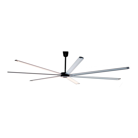
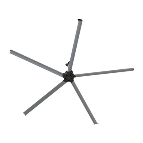
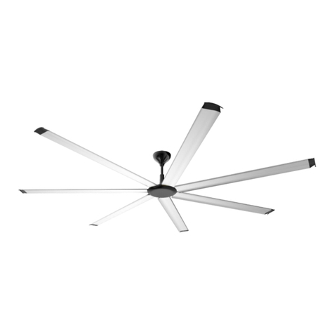
ANEMOI AIRPOLE 250 User manual

AIRPOLE
Installation Manual
Issued January 2020
ANIM17AI Rev. A

AIRPOLE
2
UPDATES
DATE
UPDATE
DESCRIPTION
16 / 01 / 2020
A
First Edition
Technical documents are regularly updated. Anemoi reserves the right to modify the contents of this manual, in full or in part,
without warning.

AIRPOLE
3
TABLE OF CONTENTS
SAFETY..................................................................................................................................................................4
1INTRODUCTION............................................................................................................................................5
2TECHNICAL CHARACTERISTICS ...............................................................................................................6
3DELIVERY .....................................................................................................................................................8
3.1 Packing List...........................................................................................................................................8
4MECHANICAL INSTALLATION....................................................................................................................9
4.1 Clearances ..........................................................................................................................................10
4.2 Pole Requirements..............................................................................................................................11
4.3 Floor Fixation.......................................................................................................................................13
4.4 Motor Assembly...................................................................................................................................13
4.5 Blades Assembly.................................................................................................................................14
4.6 Motor ventilation Grid Fixation.............................................................................................................15
4.7 Cover Fixation .....................................................................................................................................15
4.8 Control Box Installation........................................................................................................................16
5ELECTRICAL INSTALLATION ...................................................................................................................17
6FIRST SWITCH ON TEST ...........................................................................................................................18
7OPERATION................................................................................................................................................19
8MAINTENANCE...........................................................................................................................................20
9TROUBLESHOOTING.................................................................................................................................21

AIRPOLE
4
SAFETY
Before the installation, read the following warning and caution instructions:
WARNING!
Do NOT install, repair or clean the fan while it is in operation or connected to the power supply. Failure
to do so may result in serious injury or death.
Do NOT install, handle, repair or clean the fan with wet hands. Failure to do so may result in serious injury
or death.
Do NOT use wires with worn or damaged insulation. Doing so may result in serious or fatal electrical shock,
fire or other accidents.
Ensure that the wires are held securely and protected from abrasion, chaffing, overload or other
damage. Risk of serious or fatal electrical shock, fire or other accidents.
Turn OFF power to the fan if you detect any damage. Risk of serious or fatal electrical shock, fire or other
accidents.
Do NOT connect a damaged fan to the power supply. Risk of serious or fatal electrical shock, fire or other
accidents.
CAUTION!
Use proper lifting equipment to handle the motor and blade boxes. Otherwise, the fan could be damaged
and there is risk of accident.
Follow the instructions and recommendations contained in this manual carefully. Failure to do so may
result in incorrect installation.

AIRPOLE
5
1INTRODUCTION
The Anemoi AIRPOLE fan is perfect for indoor and outdoor applications where it is not possible to make ceiling
installations. It has been designed to generate a huge amount of air from the ceiling thanks to the motor power.
This fan is mainly used to increase comfort in summer by generating a smooth breeze even outdoors and can also
be used in winter using the heat located in the top coats of the building.
In addition, in combination with the traditional air conditioning systems, the use of fans allows generating important
energy savings of up 45% in winter and 25% in summer.

AIRPOLE
6
2TECHNICAL CHARACTERISTICS
AIRPOLE 250
AIRPOLE 300
AIRPOLE 350
AIRPOLE 400
AIRPOLE 450
GENERAL CHARACTERISTICS
Diameter
2.5m
3.0m
3.5m
4.0m
4.5m
Blades number
6 aluminium blades
MOTOR CHARACTERISTICS
w
Motor power
270W
270W
270W
540W
540W
Supply voltage
230VAC I, 50~60 Hz
Maximum current (A)
1.2 A
1.2 A
1.2 A
2.3 A
2.3 A
Maximum speed
100rpm
100rpm
100rpm
80rpm
70rpm
Protection degree
IP54
IP54
IP54
IP54
IP54
Sound level
50dBA
50dBA
50dBA
50dBA
50dBA
Total weight*
178kg
206kg
210kg
251kg
255kg
Motor type
Magnet motor
FAN PERFORMANCE
Airflow
100,800m3/h
144,000m3/h
169,200m3/h
223,200m3/h
273,600m3/h
Recommended
coverage **
380 m²
590 m²
760 m²
930 m²
1,130 m²
Max. Coverage ***
532 m²
826 m²
1,064 m²
1,302 m²
1,582 m²
CONTROL
Controller
Commercial VFD with potentiometer or RS485 connection
OPTIONS
Colour
Optional blade colour customization
* Depending on pole weight. ** Air speed > 0.5m/s. *** Air speed > 0.2m/s.

AIRPOLE
7
AIRPOLE 500
AIRPOLE 550
AIRPOLE 650
AIRPOLE 730
GENERAL CHARACTERISTICS
Diameter
5.0m
5.5m
6.5m
7.3m
Blades number
6 aluminium blades
MOTOR CHARACTERISTICS
w
Motor power
820W
820W
1100W
1100W
Supply voltage
230VAC I, 50~60 Hz
Maximum current (A)
3.6 A
3.6 A
5 A
5 A
Maximum speed
70rpm
60rpm
60rpm
60rpm
Protection degree
IP54
IP54
IP54
IP54
Sound level
50dBA
50dBA
50dBA
50dBA
Total weight*
291kg
293kg
306kg
320kg
Motor type
Magnet motor
FAN PERFORMANCE
Airflow
309,600m3/h
385,200m3/h
475,200m3/h
601,200m3/h
Recommended
coverage **
1,310 m²
1,490 m²
1,750 m²
2,050 m²
Max. Coverage ***
1,834 m²
2,086 m²
2,450 m²
2,870 m²
CONTROL
Controller
Commercial VFD with potentiometer or RS485 connection
OPTIONS
Colour
Optional blade colour customization
* Depending on pole weight. ** Air speed > 0.5m/s. *** Air speed > 0.2m/s.

AIRPOLE
8
3DELIVERY
The Anemoi AIRPOLE fan is delivered in two wood boxes, one including the motor parts and the other the blades.
Handle the fan boxes carefully and with proper lifting equipment to avoid any damage.
CAUTION!
Use proper lifting equipment to handle the motor and blade boxes. Otherwise, the fan could be damaged
and there is risk of accident.
3.1 Packing List
The following tables include the different pieces sent inside the boxes. Please check the status and quantity of the
fan equipment and the supporting parts immediately after you have opened the box to make sure that the goods
received are in accordance with your order. If parts are missing or damaged, please inform our company’s
responsible person immediately for revision.
Motor box:
NO.
Component name
QTY
1
Motor
1 pc
2
Control box
1 pc
3
Fan hub
1 pc
4
M22 bolts and nuts
6 pcs
5
M18 bolts and nuts
6 pcs
6
Conical cover for motor
1 pc
7
Motor ventilation grid
1 pc
8
Ventilation grid screws
6 pcs
9
Fan top cover
1 pc
10
Fan cover screws
6 pcs
11
Bolted flange
1 pc
12
Blade retainer
6 pcs
13
M6 bolts, nuts and washer
24 pcs
Blades box:
NO.
Component name
QTY
1
Fan Blade
6 pcs

AIRPOLE
9
4MECHANICAL INSTALLATION
CAUTION!
Follow the instructions and recommendations contained in this section carefully. Failure to do so may
result in incorrect installation.
The Anemoi AIRPOLE fan is designed for floor installation. Ensure that the floor area chosen can hold the weight
of the fan and that there are no obstacles in its operating range. The maximum weight of the fan is about 320kg
depending on the pole’s weight.
Before installing the fan, it is necessary to sign and protect the working area to prevent anyone from going under
the fan. It is recommended to fence at least four meters around the lifting equipment.
Follow any national or local regulation regarding installations in height.
SAFETY!
Ensure that the floor area chosen can hold the weight of the fan and that there are no obstacles in its
operating range. Failure to do so may result in equipment damage or accident.
Ensure sign and protect the working area. Failure to do so may result in serious injury or death.
Ensure following any national or local regulation. Failure to do so may result in serious injury or death.
Do NOT install the fan while it is in operation or connected to power supply. Doing so may result in serious
or fatal electrical shock.

AIRPOLE
10
4.1 Clearances
In order to ensure the maximum coverage of the Anemoi AIRPOLE, all obstacles that may be encountered within
the radius of the fan and the roof (if there is any roof) should be considered before installation, ensuring that the
fan has an appropriate clearance in all directions when running.
If there are lamps above the fan blades, change their position if necessary, to avoid the strobe effect. Ensure that
the fan is installed at a height greater than four meters.
The next figure shows all clearances:
CAUTION!
Ensure that the minimum distances are achieved. Otherwise, the fan could be damaged.
It is recommended to protect the fan if there is the possibility to receive impacts.
CAUTION!
Protect the fan if there is the possibility to receive impacts. Otherwise, the fan could be damaged.

AIRPOLE
11
4.2 Pole Requirements
The Anemoi AIRPOLE requires a pole that can be ordered to Anemoi or can be manufactured in the installation
country to avoid high transport costs.
Dimensions of the tube are as follows:

AIRPOLE
12
Recommended dimensions for the floor fixation part are:

AIRPOLE
13
4.3 Floor Fixation
The Anemoi AIRPOLE should be fixed to the floor using at least M22 bolts. It is recommended to use the
recommended floor fixation piece. The fan cannot be installed in inclined floors.
CAUTION!
Ensure that the M22 bolts are properly tightened. Failure to do so may result in equipment damage.
4.4 Motor Assembly
The AIRPOLE fan is delivered with a bolted flange so that the motor conical cover is correctly fixed to the pole.
The motor’s weight is very heavy so it must be lifted by two or three installers, or even lifting equipment.
CAUTION!
Ensure that the motor bolts are correctly fastened. Failure to do so may result in equipment damage.
Do not lift the motor weight alone. Failure to do so may result in serious injury or equipment damage.

AIRPOLE
14
4.5 Blades Assembly
To assemble the blades, it is necessary to screw the plastic end caps, and introduce and fix them to the motor
guides.
Insert the blade into the motor bracket and fix it using the M6 bolts and the blades retainer. It is necessary to
tighten the outside bolts first and then the inside bolts using the retainers.
The next figure shows the blades assembly:
The next figure shows the blades retainers assembly:
CAUTION!
Tighten the outside bolts first and then the inside bolts with the blades’ retainer. Failure to do so may
result in incorrect installation.

AIRPOLE
15
4.6 Motor ventilation Grid Fixation
The motor conical protection includes a special grid for ventilation that ventilates it. Use the screws provided to fix
it as follows:
4.7 Cover Fixation
The motor includes a special cover to protect the fan hub bolts. Use the screws provided to cover the motor as
follows:

AIRPOLE
16
4.8 Control Box Installation
The Anemoi AIRPOLE is controlled through a variable speed drive installed inside the control box
The control box is designed to be screwed directly onto a wall. To that end, it includes a hole on each corner.
Before drilling the wall, hold the control box in the desired position and mark the screw location. Please install the
control box in a safe area to prevent damage to the equipment.
CAUTION!
Install the control box in a safe area. Failure to do so may result in equipment damage.

AIRPOLE
17
5ELECTRICAL INSTALLATION
WARNING!
Follow the instructions and recommendations contained in this section. Failure to do so may result in
serious injury or death.
The Anemoi AIRPOLE motor is controlled by a variable frequency drive installed in the control box. The control
VFD is already factory configured to obtain the correct motor performance. To ensure the fan operation, the
installers must connect the VFD to the power supply and to the motor.
Before installing the VFD, it is necessary to remove power supply to prevent any accident. Check that power supply
is disconnected before starting the installation.
All cabling must comply with national and local regulations on cable cross-sections and ambient temperature.
Copper (60°C/75°C) conductors are recommended.
Follow any national or local regulation regarding electrical installations.
WARNING!
Follow national and local electrical regulations. Failure to do so may result in serious injury or death.
Check that power supply is disconnected before starting the installation. Failure to do so may result in
serious injury or death.
Do NOT install the fan with wet hands. Failure to do so may result in serious injury or death.
Do not change the VFD configuration. Otherwise, the warranty would be voided.
The Anemoi AIRPOLEengine must beconnected to the power supply with an electrical voltage of 230V (I, 50/60Hz)
through the control VFD. The control box includes a terminal box to allow for smooth connection to the power
supply.
You may use shielded or unshielded cables. The maximum cable length between the control box and the engine
should be 100m for unshielded and 50m for shielded cables. Please root the cables along the floor using the
shortest possible path.
Electrical and control wiring should be installed in separated circuits to prevent interference.
WARNING!
Do NOT use wires with worn or damaged insulation. Doing so may result in serious or fatal electrical shock,
fire or other accidents.
Ensure that the wires are held securely and protected from abrasion, chaffing, overload or other
damage. Risk of serious or fatal electrical shock, fire or other accidents.
Do NOT connect the motor to the input line directly. Failure to do so may result in equipment damage.

AIRPOLE
18
6FIRST SWITCH ON TEST
Installers must follow the following procedure for the first-time operation of the Anemoi AIRPOLE fan because
even if all fans are tested before shipping, they can be damaged during storage or shipping.
Before operation, it is recommended to recheck that all bolts and nuts are correctly fastened.
After performing all mechanical and electrical connection steps included in this manual, run the fan as follows:
1- Change the main switch to the start position.
2- Run the fan at a low speed (about 20 rpm / min) for during some minutes by turning the potentiometer.
3- Verify that there is no abnormal noise.
4- Increase its speed gradually.
In the event of any abnormal noise, please contact Anemoi or your distributor.

AIRPOLE
19
7OPERATION
The Anemoi AIRPOLE fan is operated through a VFD control panel. Once the fan is powered, follow the next steps
to start the fan:
1- Change the main switch to the start position.
2- Adjust the potentiometer to the required speed.
3- Check the speed in the VFD screen.
To stop the fan, perform the procedure in reverse.
CAUTION!
Do not use the main switch in the box to start and stop the fan. Otherwise, the warranty would be voided.

AIRPOLE
20
8MAINTENANCE
WARNING!
Do NOT repair or clean the fan while it is in operation or connected to the power supply. Doing so may
result in serious or fatal electrical shock.
Please maintain the fan as follows:
Every three months:
•Verify that the fan is working properly.
•Ensure that the fan does not make any noises or vibrations.
•Check that the blades have not received any impact.
Yearly:
•Check that there no alarms or faults in the variable speed drive located in the control box.
•Ensure that the extension rod screws are properly tightened.
•Ensure that the anchoring screws are properly tightened.
•Ensure that the blade screws are properly tightened.
•Clean the blades using a wet cloth.
•Check that the safety cable is properly fastened.
•Check that the guy wires are properly tightened.
•Check power and control connections in the control box.
This manual suits for next models
8
Table of contents
Other ANEMOI Fan manuals
Popular Fan manuals by other brands

Vaventis
Vaventis Fresh-r On-The-Wall Maintenance manual

Rowenta
Rowenta VU211 Series instruction manual

Ebmpapst
Ebmpapst W2D250-CA06-52 operating instructions

LUCCI Air
LUCCI Air AIRFUSION A Installation, operation, maintenance & warranty information

System air
System air TFC 225 P Operation and maintenance

Savoy House
Savoy House 52-190-3CN-187 owner's manual

Ebmpapst
Ebmpapst 3214 J/39H3-202 operating manual

Makita
Makita DCF203 instruction manual

Ebmpapst
Ebmpapst K3G220-CD17-01 operating instructions

Hitachi
Hitachi RPI-1.5FSRE Installation & operation manual

Ferroli
Ferroli MERCURY 2 Installation and operation manual

Salda
Salda VSA 220 M 3.0 Installation instruction