ANEMOI AIRSLIM L Series User manual

AIRSLIM [L]
Installation Manual
Issued June 2020
ANIM14DI Rev. D

AIRSLIM [L]
2
UPDATES
DATES
UPDATE
DESCRIPTION
30 / 07 / 2019
A
First Edition
11 / 09 / 2019
B
Fixing and control connections
29 / 01 / 2020
C
Update Technical Characteristics
03 / 06 / 2020
D
Update Fixation System
Technical documents are regularly updated. Anemoi reserves the right to modify the contents of this manual, in full or in part,
without warning.

AIRSLIM [L]
3
TABLE OF CONTENTS
SAFETY..................................................................................................................................................................4
1INTRODUCTION............................................................................................................................................5
2TECHNICAL CHARACTERISTICS ...............................................................................................................6
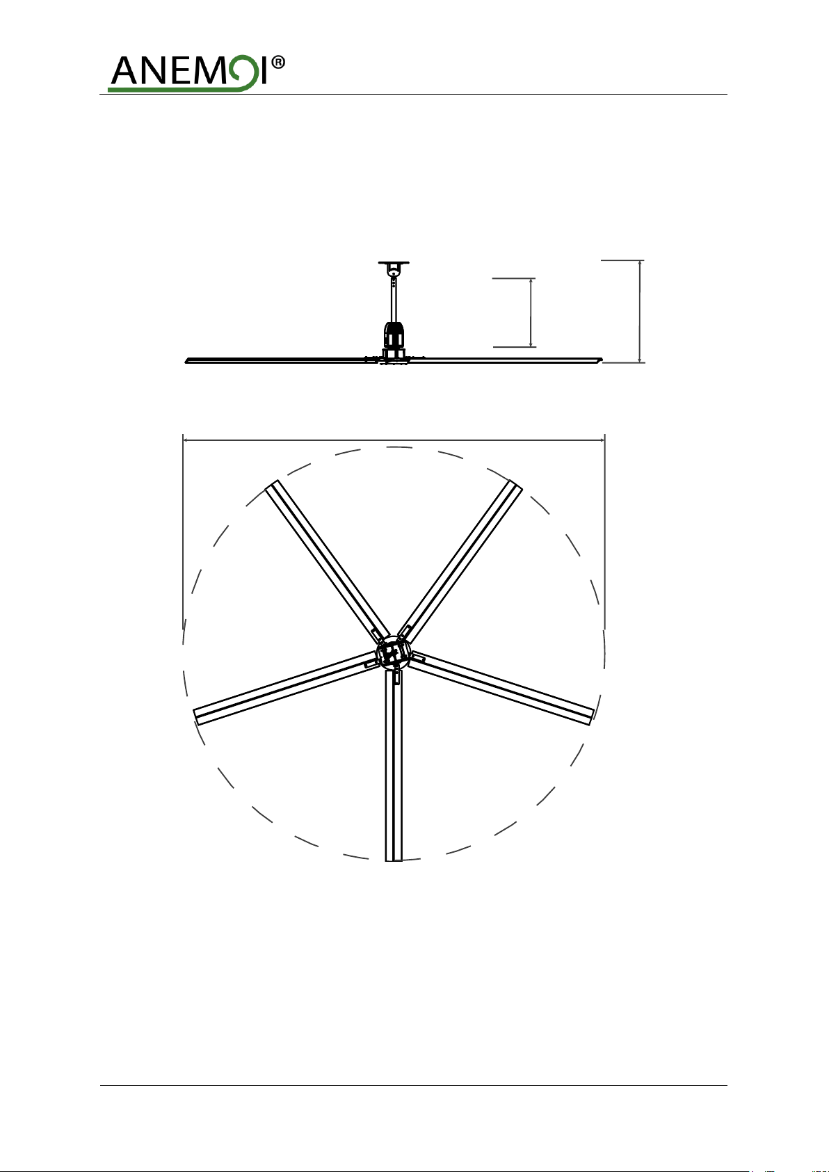
3DIMENSIONS.................................................................................................................................................7
4DELIVERY .....................................................................................................................................................8
4.1 Package Dimensions & Weights............................................................................................................8
4.2 Packing list ............................................................................................................................................8
5MECHANICAL INSTALLATION..................................................................................................................10
5.1 Clearances ..........................................................................................................................................10
5.2 Installation Tools..................................................................................................................................12
5.3 Ceiling Fixation....................................................................................................................................12
5.4 Extension Rod Assembly.....................................................................................................................13
5.5 Motor Assemby....................................................................................................................................16
5.6 Safety Cable Installation......................................................................................................................17
5.7 Controller Installation...........................................................................................................................18
5.8 Guy Wires Fixation (Optional)..............................................................................................................19
5.9 Blades Assembly.................................................................................................................................20
5.10 Cover Fixation .....................................................................................................................................21
6ELECTRICAL INSTALLATION ...................................................................................................................22
6.1 Connectors and Switches Location .....................................................................................................23
6.2 Power Connections..............................................................................................................................24
6.3 Control Connections............................................................................................................................25
6.4 Multi Fans Installation..........................................................................................................................26
6.5 Wiring installation recommendations...................................................................................................28
7MANTENAINCE...........................................................................................................................................30

AIRSLIM [L]
4
SAFETY
Before the installation, read the following warning and caution instructions:
WARNING!
Do NOT install, repair or clean the fan while it is in operation or connected to the power supply. Failure
to do so may result in serious injury or death.
Do NOT install, handle, repair or clean the fan with wet hands. Failure to do so may result in serious injury
or death.
Do NOT use wires with worn or damaged insulation. Doing so may result in serious or fatal electrical
shock, fire or other accidents.
Ensure that the wires are held securely and protected from abrasion, chaffing, overload or other
damage. Risk of serious or fatal electrical shock, fire or other accidents.
Turn Off power to the fan if you detect any damage. Risk of serious or fatal electrical shock, fire or other
accidents.
Do NOT connect a damaged fan to the power supply. Risk of serious or fatal electrical shock, fire or other
accidents.
CAUTION!
Use proper lifting equipment to handle the motor and blade boxes. Otherwise, the fan could be damaged
and there is risk of accident.
Follow the instructions and recommendations contained in this manual carefully. Failure to do so may
result in incorrect installation.

AIRSLIM [L]
5
1INTRODUCTION
The Anemoi AIRSLIM [L] fans have been designed to generate a huge volume of air from the ceiling in industrial
and commercial installations.
This low consumption fan is used to increase comfort in summer by generating a smooth breeze and also in winter
using the heat located in the top coats of the building.
The main characteristics are:
•Aluminium blades with matte black end caps.
•Integrated drive fixed to the down rod extension.
•Modbus RS485 connection for controller.
•Fire alarm stop as a NC relay.
•24VDC generated by the drive.
In addition, in combination with the traditional air conditioning systems, the use of fans allows generating
important energy savings of up 45% in winter and 25% in summer.

AIRSLIM [L]
6
2TECHNICAL CHARACTERISTICS
AIRSLIM 400L
AIRSLIM 550L
AIRSLIM 700L
GENERAL CHARACTERISTICS
Diameter
4.3m
5.5m
7.3m
Blades number
5 aluminium blades
Standard colour
Black matte colour and aluminium blades
MOTOR CHARACTERISTICS
Motor power
1000W
1000W
1500W
Supply voltage
110VAC –240VAC single phase, 50/60 Hz
Maximum consumption
500W
830W
950W
Maximum consumption (A)
2.2 A
3.6 A
4.1 A
Maximum speed
84rpm
69rpm
49rpm
Protection degree
IP20
IP20
IP20
Sound level
< 50dBA
< 50dBA
< 50dBA
Total weight
66kg
75kg
93kg
Operating temperature
-10ºC / +60ºC without derating
Motor type
Permanent magnet motor connected by Modbus RS485
FAN PERFORMANCE
Airflow*
281,198 m3/h
382,082 m3/h
719,478 m3/h
Recommended coverage**
937 m²
1274 m²
2398 m²
Maximum coverage***
1312 m²
1783 m²
3358 m²
CONTROL
Controllers
Magnocontrol
OPTIONS
Extensions
Optional rod extensions of 500, 800, 1000, 1500 & 2000 mm
Colour
Optional paint or hydroprinting
Controller
Slimcontrol or Magnocontrol 10-25
REGULATION
Certifications
CE, CB for local IEC certification
Directives
2006/42/CE
2014/35/EU
Design and construction
IEC 60335-2-80
EN 60335-1
EN 62233
* Following AMCA 230-99 ** Air Speed > 0.5 m/s *** Air Speed > 0.2 m/s

AIRSLIM [L]
7
3DIMENSIONS
The Anemoi AIRSLIM [L] comes in five different diameters. The height of the fan can also be adjusted by modifying
the length of the extension bar. The following figure shows the dimensions of the fan with a standard extension of
650 mm and total height of 1050 mm:

AIRSLIM [L]
8
4DELIVERY
The Anemoi AIRSLIM [L] fan is delivered in two wood boxes, one including the motor parts and the other the
blades. Handle the fan boxes carefully and with proper lifting equipment to avoid any damage
CAUTION!
Use proper lifting equipment to handle the motor and blade boxes. Otherwise, the fan could be damaged
and there is risk of accident.
4.1 Package Dimensions & Weights
The dimensions and weights of these boxes are listed in the following table:
Model
Box
Width (mm)
Depth (mm)
Height (mm)
Weight (kg)
AIRSLIM [L]
Motor
890
890
300
55,5
Blades
3350
420
250
42
4.2 Packing list
The following tables include the different pieces sent inside the boxes. Please check the status and quantity of
the fan equipment and the supporting parts immediately after you have opened the box to make sure that the
goods received are in accordance with your order. If parts are missing or damaged, please inform our company's
responsible person immediately for revision.
Motor Box:
Nº
Component name
Qty
1
Motor
1 pc
2
Drive
1 pc
3
Standard extension rod
1 pc
4
Standard fixing for concrete ceiling
1 pc
5
Lower engine cover
1 pc
5
Steel safety cable
1 pc
6
Installation manual
1 pc
7
Screws
Check below

AIRSLIM [L]
9
The motor box also includes the following screws:
BOLTS
Connecting with
Screw standard
QTY
Mounting system
M12*55 bolts
4
M12 Spring washer
8
M12 Nut
4
Extension rod to mounting system
M10*70 bolts
2
M10 Spring washer
4
M10 Nut
2
Extension rod to motor
M10*70 bolts
2
M10 Spring washer
4
M10 Nut
2
Safety cable
Safety cable
1
Clamp for safety cable
4
Drive
U-shaped clamp
2
M6*12 full thread bolts
4
Blades
M8*45 bolts
10
M8 Spring washer
20
M8 Nut
10
Blades box:
Nº
Component name
Qty
1
Fan Blades
5 pcs

AIRSLIM [L]
10
5MECHANICAL INSTALLATION
CAUTION!
Follow the instructions and recommendations contained in this section carefully. Failure to do so may
result in incorrect installation.
The Anemoi AIRSLIM [L] series fan is designed for ceiling installation. Ensure that theceiling area chosen can hold
the weight of the fan and that there are no obstacles in its operating range. The maximum weight of the fan is about
100kg.
Before installing the fan, it is necessary to sign and protect the working area to prevent anyone from going under
the fan. It is recommended to fence at least four meters around the lifting equipment.
Follow any national or local regulation regarding installations in height.
SAFETY!
Ensure that the ceiling area chosen can hold the weight and torque of the fan, and that there are no
obstacles in its operating range. Failure to do so may result in equipment damage or accident.
Ensure sign and protect the working area. Failure to do so may result in serious injury or death.
Ensure following any national or local regulation. Failure to do so may result in serious injury or death.
Do NOT install the fan while it is in operation or connected to the power supply. Doing so may result in
serious or fatal electrical shock.
5.1 Clearances
In order to ensure the maximum coverage of the Anemoi AIRSLIM [L], all obstacles that may be encountered
within the radius of the fan and between the horizontal height of the fan's static position and the ceiling should be
considered before installation, ensuring that the fan has an appropriate clearance in all directions when running.
If there are lamps above the fan blades, change their position if necessary, to avoid the strobe effect. Ensure that
the fan is installed at a height greater than four meters.
The next figure shows all clearances:

AIRSLIM [L]
11
If the fan is installed in an inclined roof, ensure that these minimum distances are achieved and add a higher
extension rod if necessary, to allow the fan take enough air and provide the maximum performance.
CAUTION!
Ensure that the minimum distances are achieved. Otherwise, the fan could be damaged.
It is recommended to protect the fan if there is the possibility to receive impacts.
CAUTION!
Protect the fan if there is the possibility to receive impacts. Otherwise, the fan could be damaged.

AIRSLIM [L]
12
5.2 Installation Tools
To install the fan, ensure having the following required tools:
Nº
Name
Qty
1
Standard wrench set (19, 14, 13, 10 mm)
2
2
Standard socket set with ratchet
2
3
Standard socket set
2
4
Star screwdriver
1
5
Nevel ruler 300mm
1
6
Cutting pliers
1
7
Small flat screwdriver
1
8
Wire stripper
1
9
Insulating tape
1
5.3 Ceiling Fixation
The Anemoi AIRSLIM [L] comes with mounting brackets to anchor the fan to the ceiling. As standard, all tooling is
provided so that the fan can be mounted in I beams, concrete beams and directly to the ceiling. The fan is prepared
to be installed in inclined roofs.
Part list:
1. M12*55mm Bolts (4x)
2. M12 Spring washer (8x)
3. I-Beam Clamp (2x)
4. I-Beam Spacer (2x)
5. Mounting Base (1x)
6. M12 Locked nut (4x)
Tools:
19mm Wrench
19mm Socket
Torque Wrench
Torque = 100 NM

AIRSLIM [L]
13
CAUTION!
Ensure that the M12 bolts are properly tightened. Failure to do so may result in equipment damage.
5.4 Extension Rod Assembly
CAUTION!
Ensure that power cables, control cables and safety cable pass through the ceiling bracket and through
the extension rod. Otherwise, the fan will be installed incorrectly.
Ensure to place the rectangular hole of the extension bar on the bottom. Otherwise, the fan will be installed
incorrectly.
The extension rod is assembled to the ceiling fixation by the cardan joint. The cardan joint allows also the fan to
make free oscillation and to find its own level position specially for inclined roofs.
The extension rod is assembled to the ceiling fixation by the Screws M10 x70mm provided by applying a tightening
torque of 60Nm. The extension rod has a rectangular hole in the side. This hole should be in the lower part closest
to the motor.
The following figure shows how to attach the extension rod to the roof anchor.
Push I-Beam clamp inward to center of
mean for max clamping.

AIRSLIM [L]
14
Part list:
1. M10mm Locked nut (2x)
2. M10 Spring washer (4x)
3. M10*70mm Bolt (2x)
4. Tubo de extensión rod
Tools:
14mm Wrench
14mm Socket
Torque Wrench
Torque = 60 NM
Use the level so that the extension bar
is fully vertical.
1. Lock bolts/nuts (4x)
Tools:
19mm Wrench
19mm Socket
Torque Wrench
Torque = 100 NM
CAUTION!
Ensure that the M10 motor/extension bolts are correctly fastened. Failure to do so may result in equipment
damage.
Ensure that the extensión rod is completely vertical and fixed. Failure to do so may result in equipment
damage.

AIRSLIM [L]
15
The length of the extension rod can be customized according to the installation requirements between 500, 1000,
1500 y 2000 mm. The variation of the extension rod length allows adjusting installation height of fan.
If the extension rod exceeds one meter, winds must be installed to avoid oscillations. The variation of the extension
rod allows adjusting the height at which the fan is installed.
The power cables, control cables and safety cable must pass through the ceiling bracket and through the extension
bar. The power and control cables will exit through the side hole while the safety cable through the bottom. The
following image shows the position of the cables:
CAUTION!
Ensure that the cables pass correctly through the specific holes and that their length will allow them to
be connected on the control board. Failure to do so may result in equipment damage.
CAT6 Control Cable
Power cable
Safety cable

AIRSLIM [L]
16
5.5 Motor Assemby
CAUTION!
Ensure that the cables which pass through the top of the motor are on the same side as the rectangular
window of the extension rod. Failure to do so may result in equipment damage.
Do not lift the motor weight alone. Failure to do so may result in serious injury or equipment damage.
Ensure that the M10 motor/extension screws are correctly fastened. Failure to do so may result in
equipment damage.
The motor is fixed to the extension rod by the Screws M10x70mm provided by applying a tightening torque of
60Nm. The cables coming out of the motor must be on the same side as the rectangular window of the extension
rod. The safety cable must pass through the motor through the center.
Due to the weight of the motor, it is recommended that it be raised by two people to avoid personal injury and
damage to the fan.
Part list:
1. M10mm Locked nut 2x)
2. M10 Spring washer (4x)
3. M10*70mm Bolt (2x)
4. Safety cable
5. Motor
Tools:
14mm Wrench
14mm Socket
Torque Wrench
Torque = 60 NM
Keep all electrical
cables on same
side as bolts

AIRSLIM [L]
17
5.6 Safety Cable Installation
The motor comes with an already fixed safety cable that must be fixed to prevent a motor crash once installed.
Place the safety wire on a fixed roof element.
•If the fan is installed in a concrete ceiling, drill the ceiling and insert a ring that supports the weight of the
•If the fan is installed in a steel or concrete beam, put the steel safety cable around the beam forming a
closed loop.
•
The safety cable must be fixed with the two cable clamps. The ring clamps are included in the motor box.
Part list:
1. CAT 6 Shielded Data Cable
2. Power cable
3. Safety cable
4. Clamp for safety cable (4x)
Cables 1 2 will come out of the
square hole on side of the Drop
Tube as illustrated
Cable 3 is attached to the motor and
is feed upward
SAFETY!
Ensure that the safety cable is correctly installed to prevent the fan from falling. Failure to do so may
result in serious personal injury or death and equipment damage.
Leave wire rope loose until
secured to motor

AIRSLIM [L]
18
5.7 Controller Installation
The fan motor is connected to a control board that is installed on the extension rod, just above the motor.
The control board carries a hole to pass the power and communications cables that come out through the hole of
the extension tube. The cables must be passed through this hole before proceeding to screw the plate to the
extension.
Use U-shaped clamps and four M6 screws provided by applying a tightening torque of 5Nm.
The following picture shows the installation of the control board:
Part List:
1. Drive unit
2. U-shaped clamp
3. M6*12 full thread bolts
Tools:
10mm Socket
Torque Wrench
Torque = 10 NM
Once the drive is fixed, it must be
screwed and closed with the drive
cover:
Part List:
1. Drive cover (2x)
2. M4 bolts (8x)
Power and CAT6
cables
Motor Cable

AIRSLIM [L]
19
5.8 Guy Wires Fixation (Optional)
When the extensión rod esceeds one meter, it is needed guy wires fixation to secure the fan, in order to avoid
oscillations. The extension rod must be ordered specially prepared with four perforations to connect the four
safety cables. These must be introduced into the perforations at a 45º angle, as shown in the following picture:
All steel cables must be perfectly
tensioned by the leveler to ensure
that the extension bar is upright.
CAUTION!
Fasten the guy wires clamps correctly to ensure that they cannot be unscrewed. Failure to do so may
result in equipment damage.
45 degrees of
inclination
To connect with the
eyebolts
90 Degree

AIRSLIM [L]
20
5.9 Blades Assembly
The Anemoi AIRSLIM [L] fan has five blades. To assemble the blades, it is necessary to introduce and fix them
to the motor guides.
Use the M6x25 screws, M6 nuts and M6 washer provided by applying a tightening torque of 37Nm as shown in
picture:
Part list:
1. Blades(5x)
2. M8 Spring washer (20x)
3. M8 Locked nut (10x)
4. M8*45 Bolts (10x)
Tools:
13mm Wrench
13mm Socket
Torque Wrench
Torque = 30 NM
CAUTION!
Tighten the blade screws correctly. Failure to do so may result in incorrect installation
Check that there are no objects that can avoid the blades rotation. Failure to do so may result in equipment
damage.
Repeat 5 times
This manual suits for next models
3
Table of contents
Other ANEMOI Fan manuals