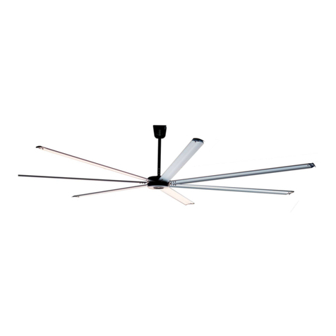
ANEMOI AIRPRO S Series User manual

AIRPRO [S]
Installation Manual
Issued July 2020
ANIM07GI Rev. G

AIRPRO [S]
2
UPDATES
DATE
UPDATE
DESCRIPTION
29 / 10 / 2018
A
First Edition
02 / 05 / 2019
B
Technical characteristics
13 / 05 / 2019
C
Update Technical Characteristics
17 / 06 / 2019
D
Update Technical Characteristics
02 / 09 / 2019
E
Modbus control
10 / 01 / 2020
F
Update Technical Characteristics
15 / 07 / 2020
G
Update
Technical documents are regularly updated. Anemoi reserves the right to modify the contents of this manual, in full or in
part, without warning.

AIRPRO [S]
3
TABLE OF CONTENTS
SAFETY............................................................................................................................................................................................................4
1INTRODUCCIÓN ...................................................................................................................................................................................5
2TECHNICAL CHARACTERISTICS.......................................................................................................................................................6
3DIMENSIONS.........................................................................................................................................................................................7
4DELIVERY .............................................................................................................................................................................................8
4.1 Package Dimensions & Weights .................................................................................................................................................8
4.2 Packing List .................................................................................................................................................................................8
5MECHANICAL INSTALLATION............................................................................................................................................................9
5.1 Ceiling Mounting..........................................................................................................................................................................9
5.2 Securing the Down Rod to the Engine ......................................................................................................................................10
5.3 Securing the Fan to the Ceiling .................................................................................................................................................11
5.4 Receiver ....................................................................................................................................................................................11
5.5 Electrical Connections to Receiving Unit...................................................................................................................................12
5.6 Mounting the Blades..................................................................................................................................................................13
6CONTROL............................................................................................................................................................................................14
6.1 Remote control ..........................................................................................................................................................................14
6.1.1 Remote control S Type ........................................................................................................................................................14
6.1.2 Remote control S Type ........................................................................................................................................................15
6.2 Modbus control..........................................................................................................................................................................15
6.2.1 Multiple Fan Installation .......................................................................................................................................................16
6.3 Wiring installation recommendations.........................................................................................................................................17
7MAINTENANCE...................................................................................................................................................................................18

AIRPRO [S]
4
SAFETY
Before the installation, read the following warning and caution instructions:
WARNING!
Do NOT install, repair or clean the fan while it is in operation or connected to the power supply. Failure
to do so may result in serious injury or death.
Do NOT install, handle, repair or clean the fan with wet hands. Failure to do so may result in serious injury
or death.
Do NOT use wires with worn or damaged insulation. Doing so may result in serious or fatal electrical shock,
fire or other accidents.
Ensure that the wires are held securely and protected from abrasion, chaffing, overload or other
damage. Risk of serious or fatal electrical shock, fire or other accidents.
Turn Off power to the fan if you detect any damage. Risk of serious or fatal electrical shock, fire or other
accidents.
Do NOT connect a damaged fan to the power supply. Risk of serious or fatal electrical shock, fire or other
accidents.

AIRPRO [S]
5
1INTRODUCCIÓN
The AIRPRO [S] series is the perfect ceiling fan to be installed in up to five meters height ceilings. The innovative
motor design with only 5cm height makes this HVLS fan very light and easy to install. This fan is built in seven
blades and the drive is integrated in the ceiling mount.
The main characteristics are:
•EC brushless motor without gearbox
•52mm ultra-thin motor
•Extremely silent fans
•7 aluminium blades
•Optional customized paint
•Remote control (RF) or Magnocontrol via Modbus

AIRPRO [S]
6
2TECHNICAL CHARACTERISTICS
AIRPRO 150 S
AIRPRO 200 S
AIRPRO 250 S
AIRPRO 300 S
GENERAL CHARACTERISTICS
Diameter
1.5 m
2.0 m
2.5 m
3.0 m
Blades number
7 aluminium blades
Standard colour
Black matte colour and aluminium blades
MOTOR CHARACTERISTICS
Motor power
100W
100W
100W
100W
Supply voltage
110VAC ~ 240VAC I, 50/60 Hz
Maximum consumption
54W/h
72W/h
84W/h
84W/h
Maximum consumption (A)
0.47 A
0.6 A
0.71 A
0.71 A
Maximum speed
180rpm
130rpm
95rpm
70rpm
Protection degree
IP20
IP20
IP20
IP20
Sound level
<35dBA
<35dBA
<35dBA
<35dBA
Total weight
14kg
16kg
18kg
20kg
Operation temperature
-10ºC ~ 40ºC without derating
Motor type
Brushless EC motor with neodymium magnets
FAN PERFORMANCE
Airflow*
29,711 m3/h
35,653 m3/h
41,595 m3/h
47,538 m3/h
Recommended coverage**
99 m²
119 m²
139 m²
158 m²
Maximum coverage***
139 m²
166 m²
194 m²
222 m²
CONTROL
Controllers
Remote controller or Magnocontrol
OPTIONS
Extensions
Optional rod extensions of 800 & 1300 mm
Colour
Optional paint or hydroprinting
Controller
Magnocontrol 10-25
REGULATION
Certifications
IECEE CB / BSMI
* Following AMCA 230-99 ** Air Speed > 0.5 m/s *** Air Speed > 0.2 m/s

AIRPRO [S]
7
3DIMENSIONS
The Anemoi AIRPRO [S] comes in four different diameters. The height of the fan can also be adjusted by modifying
the length of the extension bar. The following figure shows the dimensions of the fan with a standard extension:

AIRPRO [S]
8
4DELIVERY
The Anemoi AIRPRO [S] fan is delivered in two wood boxes, one including the motor parts and the other the
blades. Handle the fan boxes carefully and with proper lifting equipment to avoid any damage.
CAUTION!
Use proper lifting equipment to handle the motor and blade boxes. Otherwise, the fan could be damaged
and there is risk of accident.
4.1 Package Dimensions & Weights
The dimensions and weights of these boxes are listed in the following table:
Model
Box
Width (mm)
Depth (mm)
Height (mm)
Weight (kg)
AIRPRO [S]
Motor
620
620
230
11
Blades
1430
420
220
14,5
4.2 Packing List
The following tables include the different pieces sent inside the boxes. Please check the status and quantity of
the fan equipment and the supporting parts immediately after you have opened the box to make sure that the
goods received are in accordance with your order. If parts are missing or damaged, please inform our company's
responsible person immediately for revision.
Blades Box:
No.
Component name
Qty
1
Fan Blade
5 pcs
Motor Box:
No.
Component name
Qty
1
Mounting Bracket
1 pc
2
Fan Rod
1 pc
3
Fan Motor
1 pc
4
Control Box
1 pc
5
Mounting cover
1 pc
6
Remote Control
1 pc
7
M6*35 Screws
1 pc
M6 Washer
1 pc
M6 Locker nut
1 pc
8
M3*8 Screws
2 pcs
9
M6*30 Screws
21 pcs
M6 Washer
21 pcs
M6 Locker nut
21 uds

AIRPRO [S]
9
5MECHANICAL INSTALLATION
The Anemoi AIRPRO [S] fan has been designed for ceiling installation. Ensure that the ceiling area chosen can
hold the weight of the fan and that there are no obstacles in its operating range. Make sure that the fan is installed
at a height greater than 2.6m.
The fan is available in two versions, Type S or Type F, check the ceiling mounting and make sure which type is
yours. Follow the corresponding instructions.
Ceiling mounting S Type
Ceiling mounting F Type
5.1 Ceiling Mounting
S Type
F Type
Use M6 screws provided to fix the anchor to the ceiling and to support the weight of the fan (19kg max).

AIRPRO [S]
10
5.2 Securing the Down Rod to the Engine
Take the extension and motor out of the box. Loosen the screws and caps on the extension tube and pass the
safety cable and electrical cables through the tube.
Attach the extension to the motor using the extension screws. The safety cable must be fixed to the motor screw
as shown in the figure. Recommended tightening torque: 5 N.m (50 kgf.cm)
S Type
F Type
Insert the cover into the extension. Make sure that the cables pass correctly through the extension and that the
screws are properly tightened. Recommended tightening torque: 5 N.m (50 kgf.cm).
S Type
F Type
CAUTION!
Ensure that the motor cables exit correctly from the top. Otherwise, the fan may be damaged.
Security cable
Motor cable

AIRPRO [S]
11
5.3 Securing the Fan to the Ceiling
To attach the fan to the ceiling, simply place the extension ball joint in the center of the anchor previously attached
to the ceiling, as shown in the images below.
NOTE: Be careful not to pinch the cables during operation.
S Type
F Type
CAUTION!
Be careful not to press the wires during operation. Otherwise, the fan may be damaged.
5.4 Receiver
Insert the receiver into the fitting, in the F Type model the bracket screws must first be loosened.
S Type

AIRPRO [S]
12
Tipo F
CAUTION!
Ensure all cables are protected inside the top bezel. Otherwise, the fan may be damaged.
5.5 Electrical Connections to Receiving Unit
The receiving unit of the remote control should be wired as explained below:
Connect the ground wire to the Screw 2 of the hardware as shown in the figure:
S Type
F Type

AIRPRO [S]
13
5.6 Mounting the Blades
S Type / F Type
7. The engine has seven
projections that allow to fix the
seven blades to it. Each blade is
inserted in the projection by the
part that has three holes and is
fixed to the motor with:
a) Three M6x30mm
screws
b) Three M6 nuts
c) Three M6 washers

AIRPRO [S]
14
6CONTROL
The Anemoi AIRPRO [S] fan can be purchased with remote control or with Modbus control. Next, the
particularities of each of the two models are established.
6.1 Remote control
6.1.1 Remote control S Type
The Anemoi AIRPRO [S] fan isoperated through a remotecontrol. You
must pair the remote control to the fan before using it.
You need to set up the receiver for the fan to work properly. Please,
follow the following steps:
1 - Open the back cover of the control and place two AAA batteries in
the knob.
2 - Switch on the fan supply and before 30 seconds have elapsed,
press the buttons simultaneously .
3 - A beep sounds when the devices are paired correctly.
The remote control has the following switches and buttons:
1 ~ 6
Allows you to adjust fan speeds
Stops the fan
Allows operation in reverse mode (optional). To
be effective, the fan must have a set speed.

AIRPRO [S]
15
6.1.2 Remote control S Type
The Anemoi AIRPRO [S] fan is operated through a remote control.
You must pair the remote control to the fan before using it.
You need to set up the receiver for the fan to work properly. Please,
follow the following steps:
1 - Open the back cover of the control and place two AAA batteries in
the knob.
2 - Switch on the fan supply and before 30 seconds have elapsed,
press the buttons simultaneously .
3 - A beep sounds when the devices are paired correctly.
The remote control has the following switches and buttons:
6.2 Modbus control
The Anemoi AIRPRO [S] fan needs an external control to work. The external control is connected directly to the
fan control board using shielded cable type modbus cable RS485 2x2x0.50 mm² POSCY.
The following figure shows the detail of the control connectors:
1 ~ 6
Allows you to adjust fan speeds
Stops the fan
Allows operation in reverse mode (optional). To
be effective, the fan must have a set speed.

AIRPRO [S]
16
6.2.1 Multiple Fan Installation
In installations with multiple fans, it is possible to control the fans using a single controller. In this case, the
controller is connected to the different by using control connections A, B and GND.
The following figure shows the detail of the control connectors:
WARNING!
The earth meshes of each cable section must remain together. Failure to do so may lead to communication
errors.
Connect only one end of the earthing to the ground. Failure to do so may lead to communication errors.

AIRPRO [S]
17
6.3 Wiring installation recommendations
To ensure correct installation and functioning of the Modbus control fan, please keep in mind following
recommendations:
1- Please strip the wire 5cm as a maximum as shown below:
2- Communication cables cannot be wound. If it were done, they could act as an antenna. Communication
cables that are not used have to be cut and left inside the shielded tube as shown below.
3- Please keep always a distance of at least 20cm between the power and the data cable. If both cables must
cross at some point, please ensure that they do so at a 90º angle to prevent interference.
WARNING!
Do not strip the communication cable more than 5cm. Failure to do so may lead interferences.
Do not wind the unused communications cable. Failure to do so may lead interferences.
Maintain a minimum distance between electrical and communications wiring. Failure to do so may lead
interferences.
Avoid power zones. Failure to do so may lead interferences.
CONTROL
BOARD

AIRPRO [S]
18
7MAINTENANCE
Please maintain the fan as follows:
Every three months:
Clean up the dust of the fan with a dry cloth.
Verify that the fan is working properly.
Ensure that the fan does not make any noises or vibrations.
Verify that the fan is working in the correct direction.
Yearly:
Ensure that the anchoring screws and the Blade screws are properly tightened.
Remarks:
Please take the battery off if you are not going to use the fan for a long time.

www.anemoifans.com
This manual suits for next models
4
Table of contents
Other ANEMOI Fan manuals
Popular Fan manuals by other brands

Sunforce
Sunforce SOLAR ATTIC VENT user manual

Hunter
Hunter 20452 Parts guide

BLAUBERG
BLAUBERG Auto Revers series Operation manual

Vent-Axia
Vent-Axia Lo-Carbon Scala Plus Installation and wiring instructions

NuTone
NuTone 656 installation instructions

Vallox
Vallox 132 E Series Instructions for use and maintenance