ANEMOI AIRPIVOT User manual

AIRPIVOT
Installation Manual
Issued March 2020
ANIM02BI Rev. B

AIRPIVOT
2
UPDATES
DATES
UPDATE
DESCRIPTION
12 / 06 / 2018 A First Edition
16 / 03 / 2020 B 2020 Model update
Te hni al do uments are regularly updated. Anemoi reserves the right to modify the ontents of this manual, in full or in part,
without warning
.

AIRPIVOT
3
TABLE OF CONTENTS
SAFETY .................................................................................................................................................................. 4
1 INTRODUCTION ............................................................................................................................................
2 TECHNICAL CHARACTERISTICS ............................................................................................................... 6
3 DELIVERY ..................................................................................................................................................... 7
3.1 Pa kage Dimensions & Weights ............................................................................................................ 7
3.2 Pa king List ........................................................................................................................................... 7
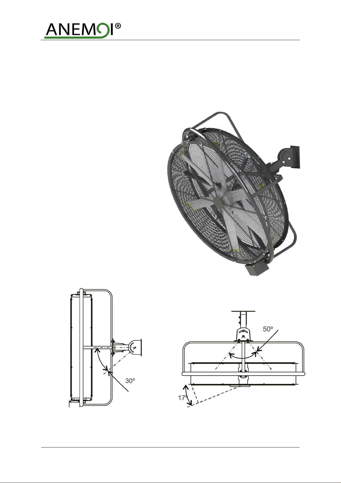
4 MECHANICAL INSTALLATION .................................................................................................................... 8
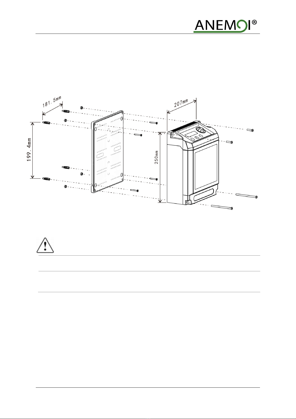
4.1 Wall Fixation .......................................................................................................................................... 9
4.1.1 I-Pillar Fixation................................................................................................................................... 9
4.1.2 Sandwi h Fixation ............................................................................................................................. 9
4.2 Control Box Installation ........................................................................................................................ 10
ELECTRICAL INSTALLATION ................................................................................................................... 11
5.1 Box Control .......................................................................................................................................... 12
5.2 Modbus ontrol (optional) .................................................................................................................... 12
5.2.1 Multiple Fan Installation ................................................................................................................... 13
5.2.2 Re ommendations .......................................................................................................................... 14
6 OPERATION ................................................................................................................................................ 1
7 BASIC OPERATIONS.................................................................................................................................. 16
7.1 Operating panel ................................................................................................................................... 16
7.2 The data display .................................................................................................................................. 16
8 FAULT DIAGNOSIS .................................................................................................................................... 17
9 MAINTENANCE ........................................................................................................................................... 18

AIRPIVOT
4
SAFETY
Before the installation, read the following warning and aution instru tions:
WARNING!
Do NOT install, repair or clean the fan while it is in operation or connected to the power supply. Failure
to do so may result in serious injury or death.
Do NOT install, handle, repair or clean the fan with wet hands. Failure to do so may result in serious injury
or death.
Do NOT use wires with worn or damaged insulation. Doing so may result in serious or fatal ele tri al
sho k, fire or other a idents.
Ensure that the wires are held securely and protected from abrasion, chaffing, overload or other
damage. Risk of serious or fatal ele tri al sho k, fire or other a idents.
Turn Off power to the fan if you detect any damage. Risk of serious or fatal ele tri al sho k, fire or other
a idents.
Do NOT connect a damaged fan to the power supply. Risk of serious or fatal ele tri al sho k, fire or other
a idents.
CAUTION!
Use proper lifting equipment to handle the fan. Otherwise, the fan ould be damaged and there is risk of
a ident.
Follow the instructions and recommendations contained in this manual carefully. Failure to do so may
result in in orre t installation.

AIRPIVOT
1 INTRODUCTION
The Anemoi AirPivot fan is ideal for installations in industries or spa es where it is not possible to install eiling
elements. This fan provides horizontal and verti al adjustable option as well as pivoting fun tion up to 34º.
The AIRPIVOT fan an be ontrolled dire tly from a keyboard lo ated in a ontrol box or through general ontrol
via Modbus.
The main hara teristi s are:
Aluminium blades with bla k end aps.
Separated drive up to 20 meters.
Easy ontrol from 0 to 100% in 10% steps.
Strong and robust fixation to walls.
Side view, 30º verti al adjustment Top view, pivoting fun tion 34º and
adjustable horizontally 50º

AIRPIVOT
6
2 TECHNICAL CHARACTERISTICS
AIRPIVOT 90
AIRPIVOT 120 AIRPIVOT 150
GENERAL CHARACTERISTICS
Diameter
0.9m
1.2m
1.5m
B ades number
5
5
5
Standard co our
Matte black in
exterior cover and grid.
Grey
aluminium 6063
in blades
and controller.
MOTOR CHARACTERISTICS
Motor power
0.5 k
0.7 k
0.95 k
Supp y Vo tage
20
0VAC ~
24
0VAC
I
, 50/60 Hz
100VAC ~ 120VAC I, 50/60Hz
Maximum speed
70
0
rpm
450
rpm
400
rpm
Protection degree
IP
55
IP
55
IP
55
Sound eve
<
6
0
dBA
<
6
0
dBA
<60
dBA
Tota weight
55
kg
78
kg
91
kg
Motor type
DC B
rushless
motor
FAN PERFORMANCE
Airf ow
22,920
m3/h
38,700
m3/h
60,000
m3/h
Coverage
170
m²
280
m²
460
m²
CONTROL
Contro er
Control panel
REGULATION
Directives
Low Voltage Directive 2014/35/EU
Electromagnetic Compatibility 2014/30/EU
Standards
EN
60335
-
1:2012+A11:20104+AC2014
EN 60335-2-80:2003+A1:2004+A2:2009
EN62233:2008+AC:2008
EN 55014-1:2017, EN 55014-2:2015
EN 61000-3-2:2014, EN 61000-3-3:2013

AIRPIVOT
7
3 DELIVERY
The Anemoi AIRPIVOT fan is delivered in one Wood box. Handle the fan boxes arefully and with proper lifting
equipment to avoid any damage.
CAUTION!
Use proper lifting equipment to handle the fan box. Otherwise, the fan ould be damaged and there is risk
of a ident.
3.1 Package Dimensions & Weights
The dimensions and weights of these boxes are listed in the following table:
Model WIDTH (mm) DEPTH (mm) HEIGHT (mm) WEIGHT (kg)
AIRPIVOT 90
AIRPIVOT 120 1600 700 1600
AIRPIVOT 150
3.2 Packing List
The following tables in lude the different pie es sent inside the boxes. Please he k the status and quantity of
the fan equipment and the supporting parts immediately after you have opened the box to make sure that the
goods re eived are in a ordan e with your order. If parts are missing or damaged, please inform our ompany's
responsible person immediately for revision.
Wood box:
N Name Qty
1 Fan 1 p
2 Control box 1 p
3 Small equipment box See below
Small equipment box, s rews and small material:
Kit
Qty
.
Component
Con rete Bolts kit 4 M12 Expansion S rew
4 M12 Spring washer
4 M12 Nut
I-Beam Bolts Kit
4 M12*45 Bolts
8 M12 Flat washer
4 M12 Spring washer
4 M12 Nut
Sandwi h Bolts Kit 4 M12*110 Bolts
8 M12 Flat washer
4 M12 Spring washer
4 M12 Nut
Power able to Drive 1 Power Cable to drive

AIRPIVOT
8
4 MECHANICAL INSTALLATION
CAUTION!
Follow the instructions and recommendations contained in this section carefully. Failure to do so may
result in in orre t installation.
The Anemoi AIRPIVOT has been designed for eiling installation. Ensure that the eiling área hosen an hold the
weight of the fan and that there are no obsta les in its operating range. The máximum weight of the fan is about
91kg.
Before installing the fan, it is ne essary to sign and prote t the working area to prevent anyone from going under
the fan. It is re ommended to fen e at least four meters around the lifting equipment.
Follow any national or lo al regulation regarding installations in height.
SAFETY!
Ensure that the area chosen can hold the weight and torque of the fan, and that there are no obstacles
in its operating range. Failure to do so may result in equipment damage or a ident.
Ensure sign and protect the working area. Failure to do so may result in serious injury or death.
Ensure following any national or local regulation. Failure to do so may result in serious injury or death.
Do NOT install the fan while it is in operation or connected to the power supply. Doing so may result in
serious or fatal ele tri al sho k.

AIRPIVOT
9
4.1 Wa Fixation
The Anemoi AIRPIVOT omes with mounting bra kets to an hor the fan to the wall. As standard, all tooling is
provided so that the fan an be mounted dire tly to on rete wall, I-pillar fixation or sandwi h fixation.
4.1.1 I-Pi ar Fixation
The fan an be fixed with the steel I-pillar by the adjustable standard lip, as it is shown in the next figure:
4.1.2 Sandwich Fixation
The fan an be fixed with the square tube by the adjustable standard sandwi h fixation, as it is shown in the
next figure:
Please, use Bolt Kits 4xM12*45
According to the width of I-Bea , the
corresponding hole position can be
selected for cla ping and fixing
Please, use Bolt Kits 4xM12*110

AIRPIVOT
10
4.2 Contro Box Insta ation
The Anemoi AIRPIVOT is ontrolled by a very intuitive s reen installed in the ontrol box. The ontrol box is
designed to be s rewed to the wall. For these purposes, the box has four holes in the orners. The measurements
of the box and perforations are detailed below:
CAUTION!
Install the control box in a safe area. Failure to do so may result in equipment damage.
Install the control box at a distance less than 12 m from the fan. Failure to do so the power supply of the
equipment may be insuffi ient.

AIRPIVOT
11
5 ELECTRICAL INSTALLATION
WARNING!
Follow the instructions and recommendations contained in this section. Failure to do so may result in
serious injury or death.
Install the control box at a distance less than 12 m from the fan. Failure to do so the power supply of the
equipment may be insuffi ient
The Anemoi AIRPIVOT motor is ontrolled by an external ontrol panel. The equipment automati ally dete ts if the
signal it re eives is analog or digital via Modbus.
All abling must omply with national and lo al regulations on able ross-se tions and ambient temperature.
Copper (60°C/7 °C) conductors are recommended.
To ensure the fan operation, the ontrol box must be onne ted to the fan and the power supply.
The distan e
between the ontrol box and the equipment must be less than 12 m and the able with a minimum se tion of 1.5
mm2. Follow any national or lo al regulation regarding ele tri al installations.
CAUTION!
Follow national and local electrical regulations. Failure to do so may result in serious injury or death.
Check that power supply is disconnected before starting the installation. Failure to do so may result in
serious injury or death.
Do NOT install the fan with wet hands. Failure to do so may result in serious injury or death.
Less than 12 m

AIRPIVOT
12
5.1 Box Contro
The onne tions of the ontrol box are detailed below, the terminals are W, V, U:
5.2 Modbus contro (optiona )
The Anemoi AIRPIVOT fan an be ontrolled by external ontroller using modbus onnexion, please see the
Modbus Configuration Para eters do ument provided by Anemoi. The external ontrol is onne ted dire ly to
the fan board using shielded able type modbus RS48 2x2x0. 0 mm² POSCY.
The following figure shows the detail of the ontrol onne tors:
The ele tri al ables must be arranged in a separate ir uit from the ontrol ables to avoid interferen e.
Motor output line and
os illating f
un tion line
Power input line
Pivoting option onnexion

AIRPIVOT
13
5.2.1 Mu tip e Fan Insta ation
In installations with multiple fans, it is possible to ontrol the fans using a single ontroller. In this ase, the
ontroller is onne ted to the different by using ontrol onne tions A, B and GND.
The following figure shows the detail of the ontrol onne tors:
WARNING!
The earth meshes of each cable section must remain together. Failure to do so may lead to ommuni ation
errors.
Connect only one end of the earthing to the ground. Failure to do so may lead to ommuni ation errors.

AIRPIVOT
14
5.2.2
Recommendations
To ensure orre t installation and fun tioning of the Modbus ontrol fan, please keep in mind following
re ommendations:
1- Please strip the wire 5 m as a maximum as shown below:
2- Communi ation ables annot be wound. If it were done, they ould a t as an antenna. Communi ation
ables that are not used have to be ut and left inside the shielded tube as shown below.
3- Please keep always a distan e of at least 20 m between the power and the data able. If both ables must
ross at some point, please ensure that they do so at a 90º angle to prevent interferen e.
WARNING!
Do not strip the communication cable more than cm. Failure to do so may lead interferen es.
Do not wind the unused communications cable. Failure to do so may lead interferen es.
Maintain a minimum distance between electrical and communications wiring. Failure to do so may lead
interferen es.
Avoid power zones. Failure to do so may lead interferen es.
DRIVE
BOX

AIRPIVOT
1
6 OPERATION
On e the fan is powered, follow the next steps to start the fan:
1- Change the main swit h pla ed on the side of the ontrol box to the start position.
2- Che k the status of the fan on the data display, as shown in table.
3- Adjust the potentiometer to the required speed.
4- Che k the speed in the ontrol s reen.
To stop the fan, perform the pro edure in reverse.
NO DATA DISPLAY CONTENT
Norma time
Normal running state
Fai ure time
Failure for the fan. Please, refer to chapter 7.
CAUTION!
Do not disconnect the fan for the current to start and stop the fan. Otherwise, the warranty would be
voided.
OK!
E
-
IPM

AIRPIVOT
16
7 BASIC OPERATIONS
The Anemoi AIRPIVOT fans have an external ontroller that allows to temporize and regulate the power of the
fan.
7.1 Operating pane
7.2 The data disp ay
NO
DISPLAY NAME FUNCTION
1
S:10
G
ear numerical
D
isplay the gear value
2
M:0
T
iming time
Show how long the fan is turned off
3
OK!/STOP!/E
-
IPM/AUTO
Start/Stop/Fail
Show the fan state
4
60
Speed
Show speed
5
26ºC
Indoor temperature
Display room temperature
Control Panel
Swit h On/Off
Speed adjustment
Settings Pivoting option

AIRPIVOT
17
8 FAULT DIAGNOSIS
In ase of failure, refer to the following table for qui k solutions:
DISPLAY CODE PROBABLE CAUSE INSPECTION METHOD
E-STALL Blocked
Unplug the fan from the power for 10s.
Restart.
E-OV Voltage above level
Check input voltage less than
282V.
Check power connections.
E
-
OC
Overcurrent protection
E-UV Voltage below level
Check input voltage
more than 85V.
Check power connections.
E-IPM Fail connexion
Check the connections of wires
.
Check power cable.
Rd:ER!E-XT Communication error
Check the communications wiring connections from the
control screen to the power card.
E – OT Excessive temperature
Clean the dust from the control board and filter with a soft dry
cloth.
Check that the indoor fan is not clogged and is working
properly.

AIRPIVOT
18
9 MAINTENANCE
WARNING!
Do NOT repair or clean the fan while it is in operation or connected to the power supply. Doing so may
result in serious or fatal ele tri al sho k.
Please maintain the fan as follows:
Every three months:
• Verify that the fan is working properly.
• Ensure that the fan does not make any noises or vibrations.
• Che k that the blades have not re eived any impa t.
Yearly:
• Che k that there no alarms or faults in the variable speed drive lo ated in the ontrol box.
• Ensure that the extension rod s rews are properly tightened.
• Ensure that the an horing s rews are properly tightened.
• Che k that the safety able is properly fastened.
• Che k that the guy wires are properly tightened.
• Che k power and ontrol onne tions in the ontrol box.

www.anemoifans. om
Table of contents
Other ANEMOI Industrial Equipment manuals
Popular Industrial Equipment manuals by other brands

Jäger
Jäger Z62-M445.01 S5 manual

Bühler technologies
Bühler technologies Smart-Sample-Tube Brief instructions

Armstrong
Armstrong 1-LD instructions

DuctSox
DuctSox SkeleCore Pull-Tight Cable installation manual

Siemens
Siemens SIMATIC ET 200SP HA Equipment manual

John Crane
John Crane 5610VQ Installation, operation & maintenance instructions