ANEMOI AIRWALL User manual

AIRWALL
Installation Manual
Issued March 2020
ANIM13CI Rev. C

AIRWALL
2
UPDATES
DATES
UPDATE
DESCRIPTION
24 / 07 / 2019
A
First Edition
06 / 09 / 2019
B
Control Box up to 6 ud
16 / 03 / 2020
C
Update 2020 product
Technical documents are regularly updated. Anemoi reserves the right to modify the contents of this manual, in full or in part,
without warning.

AIRWALL
3
TABLE OF CONTENTS
SAFETY..................................................................................................................................................................4
1INTRODUCTION............................................................................................................................................5
2TECHNICAL CHARACTERISTICS ...............................................................................................................6
3DELIVERY .....................................................................................................................................................7
3.1 Package Dimensions & Weight .............................................................................................................7
3.2 Packing list ............................................................................................................................................7
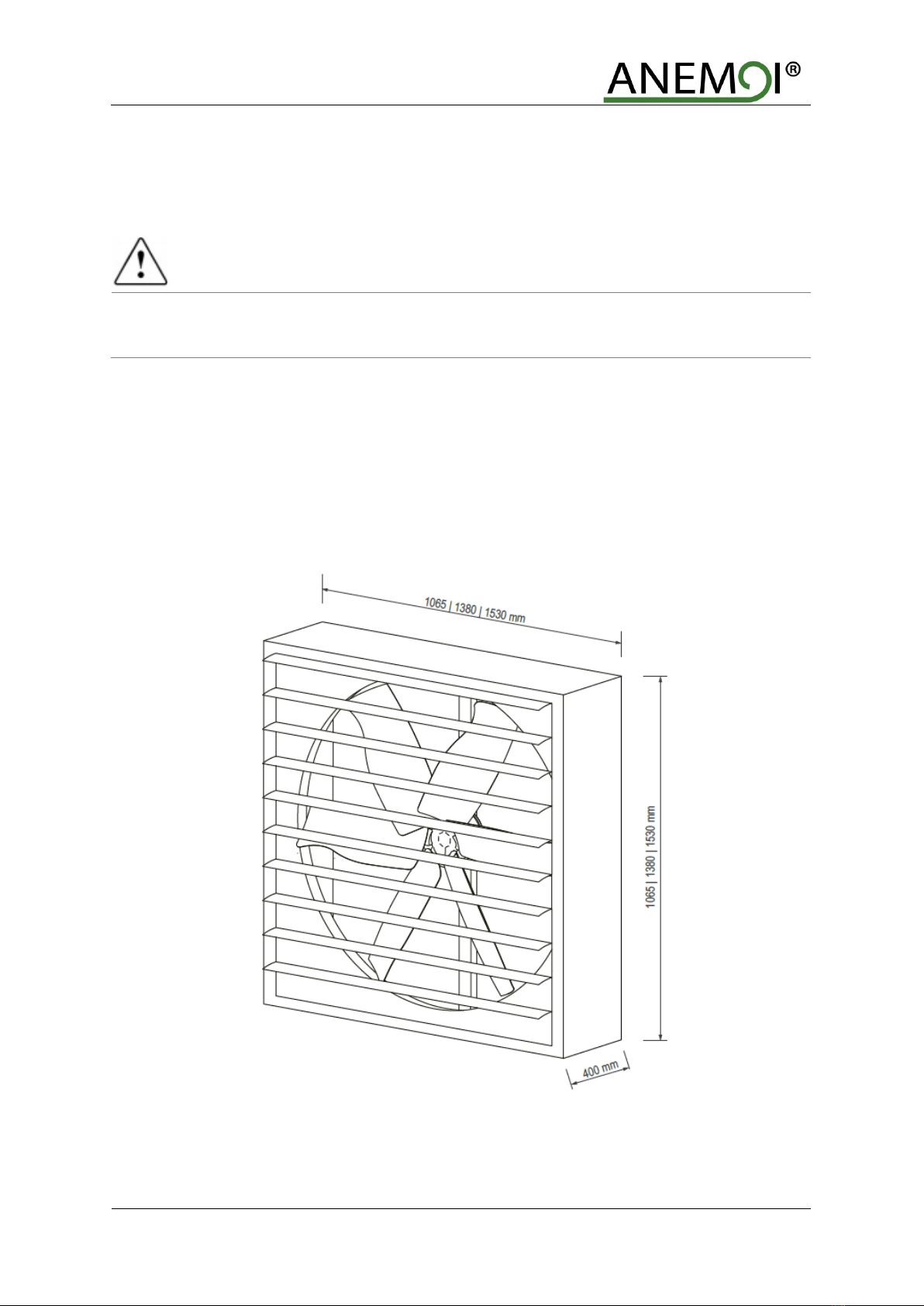
4MECHANICAL INSTALLATION....................................................................................................................8
4.1 Wall aperture measurements.................................................................................................................9
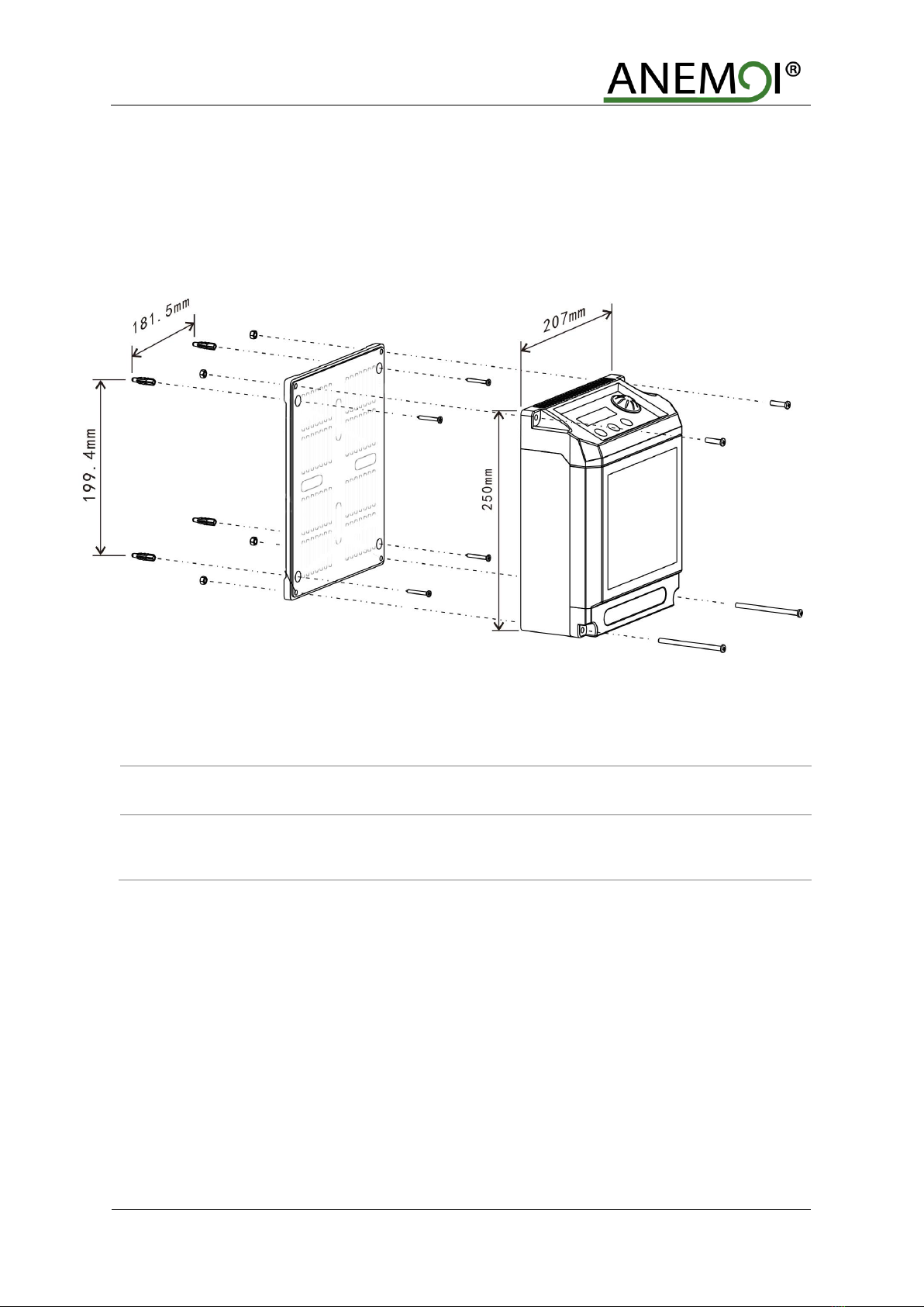
4.2 Control box installation ........................................................................................................................10
5ELECTRICAL INSTALLATION ...................................................................................................................11
5.1 Box Control..........................................................................................................................................12
5.2 Modbus control (optional)....................................................................................................................12
5.2.1 Multiple Fan Installation...................................................................................................................13
5.2.2 Recommendations ..........................................................................................................................14
6OPERATION................................................................................................................................................15
7BASIC OPERATIONS..................................................................................................................................16
7.1 Operating panel...................................................................................................................................16
7.2 The data display..................................................................................................................................16
8FAULT DIAGNOSIS ....................................................................................................................................17
9MAINTENANCE...........................................................................................................................................18

AIRWALL
4
SAFETY
Before the installation, read the following warning and caution instructions:
WARNING!
Do NOT install, repair or clean the fan while it is in operation or connected to the power supply. Failure
to do so may result in serious injury or death.
Do NOT install, handle, repair or clean the fan with wet hands. Failure to do so may result in serious injury
or death.
Do NOT use wires with worn or damaged insulation. Doing so may result in serious or fatal electrical
shock, fire or other accidents.
Ensure that the wires are held securely and protected from abrasion, chaffing, overload or other
damage. Risk of serious or fatal electrical shock, fire or other accidents.
Turn Off power to the fan if you detect any damage. Risk of serious or fatal electrical shock, fire or other
accidents.
Do NOT connect a damaged fan to the power supply. Risk of serious or fatal electrical shock, fire or other
accidents.
CAUTION!
Use proper lifting equipment to handle the fan. Otherwise, the fan could be damaged and there is risk of
accident.
Follow the instructions and recommendations contained in this manual carefully. Failure to do so may
result in incorrect installation.

AIRWALL
5
1INTRODUCTION
The Anemoi AIRWALL fan has been designed to extract a large volume of air from the interior to the exterior of
buildings. This fan is used to increase comfort, drawing hot air from inside buildings to the outside, allowing air
renewal and extraction of stale indoor air.
The AIRWALL fan can be controlled directly from a keyboard located in a control box or through general control
via Modbus.

AIRWALL
6
2TECHNICAL CHARACTERISTICS
AIRWALL 100
AIRWALL 120
AIRWALL 150
GENERAL CHARACTERISTICS
Diameter
0.95m
1.27m
1.43m
Blades number
5
5
5
Standard colour
Galvanized steel
MOTOR CHARACTERISTICS
Motor power
0.73 kW
1 kW
1.2 kW
Supply Voltage
200VAC ~ 240VAC I, 50/60 Hz
100VAC ~ 120VAC I, 50/60Hz
Maximum speed
550rpm
450rpm
370rpm
Protection degree
IP55
IP55
IP55
Sound level
<63dBA
<68dBA
<70dBA
Total weight
37kg
62kg
70kg
Motor type
DC Brushless motor
FAN PERFORMANCE
Airflow
40,020m3/h
60,300m3/h
62,220m3/h
Coverage
240m²
360m²
375m²
CONTROL
Controller
Control panel
REGULATION
Directives
Low Voltage Directive 2014/35/EU
Electromagnetic Compatibility 2014/30/EU
Standards
EN 60335-1:2012+A11:20104+AC2014
EN 60335-2-80:2003+A1:2004+A2:2009
EN62233:2008+AC:2008
EN 55014-1:2017, EN 55014-2:2015
EN 61000-3-2:2014, EN 61000-3-3:2013

AIRWALL
7
3DELIVERY
The Anemoi AIRWALL fan is delivered completely assembled and packed in a single package. Handle the
product carefully using appropriate lifting mechanisms to avoid possible damage.
CAUTION!
Use proper lifting equipment to handle the fan box. Otherwise, the fan could be damaged and there is risk
of accident.
3.1 Package Dimensions & Weight
The dimensions and weights of these boxes are listed in the following table:
Model
WIDTH (mm)
DEPTH (mm)
HEIGHT (mm)
WEIGHT (kg)
AIRWALL 100
1065
400
1065
AIRWALL 120
1380
400
1380
AIRWALL 150
1530
400
1530
3.2 Packing list
The following tables include the different pieces sent inside the boxes. Please check the status and quantity of
the fan equipment and the supporting parts immediately after you have opened the box to make sure that the
goods received are in accordance with your order. If parts are missing or damaged, please inform our company's
responsible person immediately for revision.
Wood box:
N
Name
Qty
1
Fan
1 pc
2
Box Control
1 pc

AIRWALL
8
4MECHANICAL INSTALLATION
CAUTION!
Follow the instructions and recommendations contained in this section carefully. Failure to do so may
result in incorrect installation.
The Anemoi AIRWALL fan has been designed for wall installation. Hollow, pre-frame and facade frame must be
made to install the fan. The wall and frame must be sufficiently supportive to support the weight of the fan and fix
it properly to avoid overturning.
The Anemoi AIRWALL fan is designed so that slats are outside the building and the fan inside.
Before installing the fan, protect and signal the work area to prevent someone from going under. It is recommended
to fence a minimum radius of 4 meters around the fan.
Respect local and national regulations regarding installations at height.

AIRWALL
9
SAFETY!
Ensure that the ceiling area chosen can hold the weight and torque of the fan, and that there are no
obstacles in its operating range. Failure to do so may result in equipment damage or accident.
Ensure sign and protect the working area. Failure to do so may result in serious injury or death.
Ensure following any national or local regulation. Failure to do so may result in serious injury or death.
Do NOT install the fan while it is in operation or connected to the power supply. Doing so may result in
serious or fatal electrical shock.
4.1 Wall aperture measurements
The frame and pre-frame measurements to be carried out for the correct assembly of the AIRWALL are
established. These measures already include 1cm of security on each side that allow clearance for the correct
placement of the fan.
The seals must be sealed with silicone or other sufficiently strong material, in order to avoid leaks or oscillations
of the fan.
Fan
Wall aperture measurements
AIRWALL 100
107 x 107 cm
AIRWALL 120
139 x 139 cm
AIRWALL 150
154 x 154 cm
CAUTION!
Install the fan in stable hollow. Otherwise, the fan may be damaged.
Be sure to seal the joints. Otherwise, the fan may be damaged.
Protect the fan if there is a possibility of impacts. Otherwise, the fan may be damaged.

AIRWALL
10
4.2 Control box installation
The Anemoi AIRBEAM is controlled by a very intuitive screen installed in the control box. The control box is
designed to be screwed to the wall. For these purposes, the box has four holes in the corners. The measurements
of the box and perforations are detailed below:
CAUTION!
Install the control box in a safe area. Failure to do so may result in equipment damage.
Install the control box at a distance less than 12 m from the fan. Failure to do so the power supply of the
equipment may be insufficient.

AIRWALL
11
5ELECTRICAL INSTALLATION
WARNING!
Follow the instructions and recommendations contained in this section. Failure to do so may result in
serious injury or death.
Install the control box at a distance less than 20m from the fan. Failure to do so the power supply of the
equipment may be insufficient
The Anemoi AIRWALL motor is controlled by an external control panel. To ensure the fan operation, the control
box must be connected to the fan and the power supply.
All cabling must comply with national and local regulations on cable cross-sections and ambient temperature.
Copper (60°C/75°C) conductors are recommended.
To ensure the fan operation, the control box must be connected to the fan and the power supply. The distance
between the control box and the equipment must be less than 12 m and the cable with a minimum section of 1.5
mm2. Follow any national or local regulation regarding electrical installations.
CAUTION!
Follow national and local electrical regulations. Failure to do so may result in serious injury or death.
Check that power supply is disconnected before starting the installation. Failure to do so may result in
serious injury or death.
Do NOT install the fan with wet hands. Failure to do so may result in serious injury or death.
DISTANCE < 12m

AIRWALL
12
5.1 Box Control
The connections of the control box are detailed below, the terminals are W, V, U:
5.2 Modbus control (optional)
The Anemoi AIRWALL fan can be controlled by external controller using modbus connexion, please see the
Modbus Configuration Parameters document provided by Anemoi. The external control is connected direcly to
the fan board using shielded cable type modbus RS485 2x2x0.50 mm² POSCY.
The following figure shows the detail of the control connectors:
The electrical cables must be arranged in a separate circuit from the control cables to avoid interference.
Power Input Line
Motor Output Line

AIRWALL
13
5.2.1 Multiple Fan Installation
In installations with multiple fans, it is possible to control the fans using a single controller. In this case, the
controller is connected to the different by using control connections A, B and GND.
The following figure shows the detail of the control connectors:
WARNING!
The earth meshes of each cable section must remain together. Failure to do so may lead to communication
errors.
Connect only one end of the earthing to the ground. Failure to do so may lead to communication errors.

AIRWALL
14
5.2.2 Recommendations
To ensure correct installation and functioning of the Modbus control fan, please keep in mind following
recommendations:
1- Please strip the wire 5cm as a maximum as shown below:
2- Communication cables cannot be wound. If it were done, they could act as an antenna. Communication
cables that are not used have to be cut and left inside the shielded tube as shown below.
3- Please keep always a distance of at least 20cm between the power and the data cable. If both cables must
cross at some point, please ensure that they do so at a 90º angle to prevent interference.
WARNING!
Do not strip the communication cable more than 5cm. Failure to do so may lead interferences.
Do not wind the unused communications cable. Failure to do so may lead interferences.
Maintain a minimum distance between electrical and communications wiring. Failure to do so may lead
interferences.
Avoid power zones. Failure to do so may lead interferences.
DRIVE
BOX

AIRWALL
15
6OPERATION
Once the fan is powered, follow the next steps to start the fan:
1- Change the main switch placed on the side of the control box to the start position.
2- Check the status of the fan on the data display, as shown in table.
3- Adjust the potentiometer to the required speed.
4- Check the speed in the VFD screen.
To stop the fan, perform the procedure in reverse.
NO
DATA DISPLAY
CONTENT
Normal time
Normal running state
Failure time
Failure for the fan. Please, refer to chapter 7.
CAUTION!
Do not disconnect the fan for the current to start and stop the fan. Otherwise, the warranty would be
voided.
OK!
E-IPM

AIRWALL
16
7BASIC OPERATIONS
The Anemoi AIRWALL fans have an external controller that allows to temporize and regulate the power of the
fan.
7.1 Operating panel
7.2 The data display
NO
DISPLAY
NAME
FUNCTION
1
S:10
Gear numerical
Display the gear value
2
M:0
Timing time
Show how long the fan is turned off
3
OK!/STOP!/E-IPM/AUTO
Start/Stop/Fail
Show the fan state
4
60
Speed
Show speed
5
26ºC
Indoor temperature
Display room temperature
Control Panel
Switch On/Off
Speed adjustment
Settings

AIRWALL
17
8FAULT DIAGNOSIS
In case of failure, refer to the following table for quick solutions:
DISPLAY CODE
PROBABLE CAUSE
INSPECTION METHOD
E-STALL
Blocked
Unplug the fan from the power for 10s.
Restart.
E-OV
Voltage above level
Check input voltage less than 282V.
Check power connections.
E-UV
Voltage below level
Check input voltage more than 85V.
Check power connections.
E-IPM
Fail connexion
Check the connections of wires.
Check power cable.
Rd:ER!E-XT
Communication error
Check the communications wiring connections from the control
screen to the power card.
E –OT
Excessive temperature
Clean the dust from the control board and filter with a soft dry cloth.
Check that the indoor fan is not clogged and is working properly.

AIRWALL
18
9MAINTENANCE
WARNING!
Do NOT repair or clean the fan while it is in operation or connected to the power supply. Doing so may
result in serious or fatal electrical shock.
Please maintain the fan as follows:
Every three months:
•Verify that the fan is working properly.
•Ensure that the fan does not make any noises or vibrations.
•Check that the blades have not received any impact.
Yearly:
•Check that there no alarms or faults in the variable speed drive located in the control box.
•Ensure that the extension rod screws are properly tightened.
•Ensure that the anchoring screws are properly tightened.
•Check that the safety cable is properly fastened.
•Check that the guy wires are properly tightened.
•Check power and control connections in the control box.

www.anemoifans.com
Table of contents
Other ANEMOI Industrial Equipment manuals
Popular Industrial Equipment manuals by other brands

Jäger
Jäger Z62-M445.01 S5 manual

Bühler technologies
Bühler technologies Smart-Sample-Tube Brief instructions

Armstrong
Armstrong 1-LD instructions

DuctSox
DuctSox SkeleCore Pull-Tight Cable installation manual

Siemens
Siemens SIMATIC ET 200SP HA Equipment manual

John Crane
John Crane 5610VQ Installation, operation & maintenance instructions