-3-
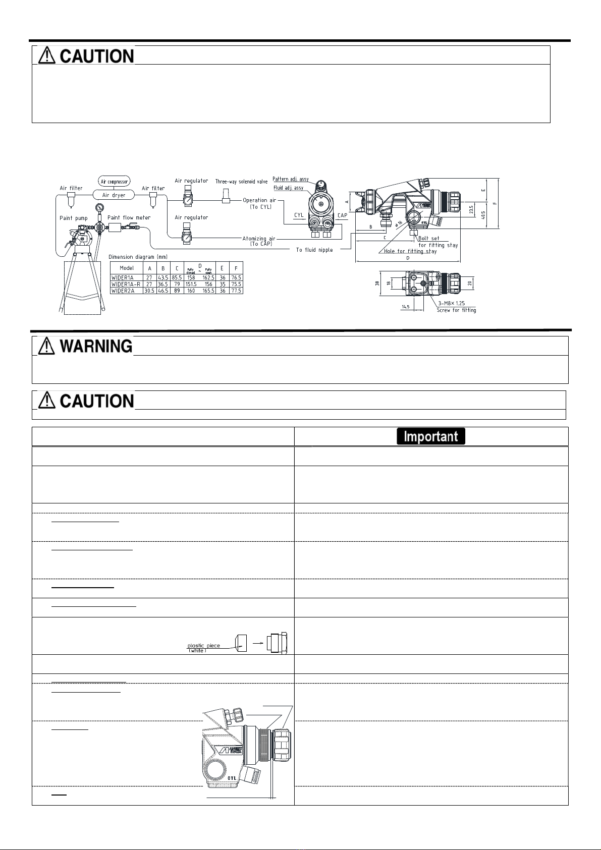
How to connect
Step1
Fit the gun to fitting stay, aim at spraying direction and fix it.
Step2
Connect atomizing air hose to atomizing air side (Cap marked side) and operating air hose to operating air side( CYL marked side).
Step3
Connect fluid hose to fluid inlet side.
Step4
supply thinner to automatic gun. Spray and clean fluid passage with thinner.
Step5
supply paint to automatic gun and test spray and adjust air volume, fluid output and pattern width as necessary.
Maintenance and inspection
Use clean air filtered through air dryer and air filter. ・・・If not, dirty air can cause painting failure.
If you use this gun for the first time after purchasing, clean fluid passages spraying thinner and remove rust preventive oil.
If not, remaining preventive oil can cause painting failure such as fish eyes.
Use three-way solenoid valve of more than φ4 inner dia. cross-sectional area and air hose of overφ6 inner dia. and less than 10m length.
If not, small dia. of solenoid valve and longer air hose between three-way solenoid valve and gun can cause delay in operation.
Firmly fix hose to spray gun.・・・If not, disconnection of hose and drop of container can cause bodily injury.
First release air and pressure fully according to item No. 3 of “Improper use of equipment” of WARNING on page 2.
Only an experienced person who is fully knowledgeable of the equipment should perform maintenance and inspection.
Use neutral cleaner: pH value shall be 6 to 8, otherwise could cause corrosion.
Only use genuine ANEST IWATA parts for any maintenance or repairs.
Step-by-step procedure
Pourremaining paintto anothercontainer. Cleanfluidpassagesandaircapassy.
Sprayasmallamountofthinner into fluidpassagesto clean them.
Incomplete cleaningcanresultinpoorspraypattern and contaminated
It isespecially importantclean the gun fullyandpromptlyafter using two-componentpaint.
Cleaneachsectionwithbrush soakedwiththinnerandwipe outwith wastecloth.
Soakingwhole sprayguninsolventmaycausespraygunmalfunction.
Alsosoakingaircapassy.itself
forextendedperiodmaycauseadefective spraypattern.
When cleaning, neverscratchthe aircap assy.,fluid nozzle, orfluidneedle.
Avoid touching ordamaging the tip of the fluid nozzle or needle.
y, fully clean fluidpassages.
Duringdisassembly,donotscratch seatsection.
Use ringspanner,boxwrenchoroptionalexclusive spanner(codeNo.035386000)
to disassemble fluid nozzle.
Remove fluid nozzle after
removing fluid needle set or while keeping fluid needle pulled,in order to
protectseatsection.
Remove fluidadj.setandpulloutfluid needlesetfrom gun body.
Payattention so that spring does notsuddenly fly out since fluid adj. set is strongly pushed by fluid
needlespringand piston spring.
Pullfluidneedlesetafterloosening fluidneedle packingsetto protectfluidneedle packing set.
Screwrearsectionoffluidneedlesetintopistonandpulloutpiston set.
Be carefulnotto damagepistonpacking whenpulling outpiston set.
Useacommerciallyavailableboxwrench (14mm).
Be carefulnotto damageO ringandseat sectionwhendisassembleair valve seatassy.
When you want to adjust fluid needle packing set, first tighten it by hand while fluid needle set
remains inserted.Thentightenit further about1/6turn (60-degree)byspanner.
When you removeneedle packingset, donotleave
plasticpieceofneedle packingsetinthegunbody
Ifyoutightenfluidneedlepackingsettoomuch,fluidneedlesetwillnotmovesmoothly,resultinginpaint
leakage from tip offluid nozzle. Try to adjust it carefully while pulling piston and confirming movement
of fluidneedleset.
When you tighten ittoo much,firstfullyloosenit and thentightenit again carefully.
knob counterclockwise to fully open.And
then tighten pattern adj. guide into gun
body.
Iffluidadj.setisnotfullyopened,tipofitcan contactanddamagetipofgunbodysetandcauseseizure
of thread.
How to install on the body
To assemble the Fluid adj. assy, open the Fluid adj. assy
fullyandapplysilicone-freegreaseoroilto thethreads.
To install/removethe Fluidadj.assy,turnthe knurled part.
If fluid adj. set is not fully opened, tip seat
t and damage fluid nozzle and cause
seizureofthread.
To adjust the Fluid adj. assy, turn the groove on the knob
part.
The standard forfully closing the paint adjustment device is
that the gap between the guide and the knob is WIDER1A:
2mm,WIDER2A:1 mm: WIDER2A:1 mm.
Donotovertighten.
tighten,thenozzle will be deformed.
Donotdisassemble theFluid adj.assy.
If youdisassemble it, you may notbeable toreassembleitdue to lossofparts.
knurled part
Distance between guide and knob