annke HD SERIES User manual

HD DVR Series
Quick Start Guide
Version 1.1.0

2
Thank you for purchasing our DVR!
This quick start guide will help you become familiar with our DVR in a very short time.
Before installation and operation, please read the following safeguard and warning carefully!
Important Safeguard and Warning
All installation and operation here should conform to your local electrical safety codes.
We assume no liability or responsibility for all the fires or electrical shock caused by
improper handling or installation.
We are not liable for any problems caused by unauthorized modifications or attempted repair.
Improper battery use may result in fire, explosion, or personal injury!
When replace the battery, please make sure you are using the same model!
Note: All the installation and operations here should conform to your local
electric safety rules.
1. Check Unpacked DVR
When you receive the DVR from the forwarding agent, please check whether there is any visible
damage. The protective materials used for the package of the DVR can protect most accidental
clashes during transportation. Then you can open the box to check the accessories.
Please check the items in accordance with the list on the warranty card (Remote control is
optional). Finally you can remove the protective film of the DVR.
2. About Front Panel and Rear Panel
The model in the front panel is very important; please check according to your purchase order.
The label in the rear panel is very important too. Usually we need you to represent the serial
number when we provide the service after sales.
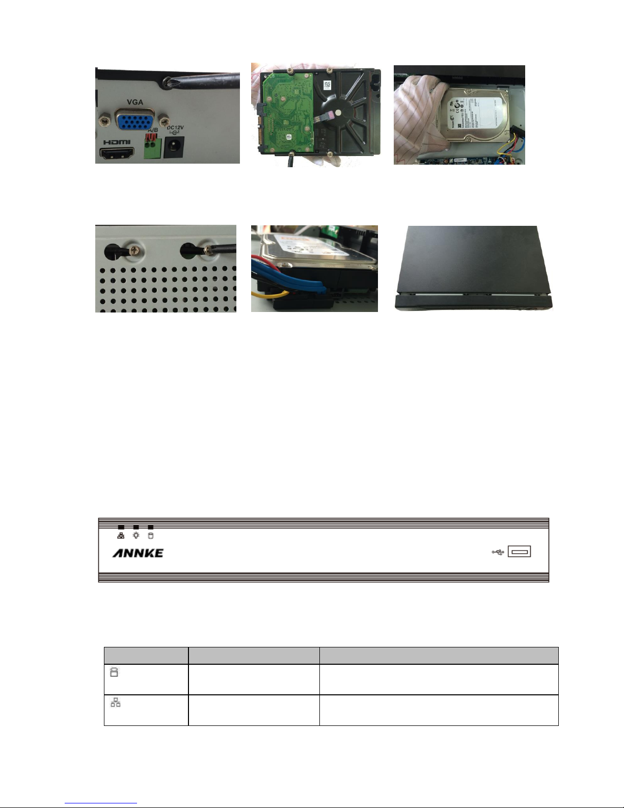
3. HDD Installation
This series DVR has only one SATA HDD. Please use HDD of 7200rpm or higher.
Please follow the instructions below to install hard disk.
Important
Shut down the device and then unplug the power cable before you open the case to
replace the HDD!

3
①Loosen the screws of the upper
cover and side panel.
②Fix four screws in the HDD
(Turn just three rounds).
③Place the HDD in accordance with the
four holes in the bottom.
④Turn the device upside down and
then turn the screws in firmly.
⑤Connect the HDD cable and
power cable.
⑥Put the cover in accordance with the
clip and then place the upper cover back.
Secure the screws in the rear panel and
the side panel.
Note:
You can connect the HDD data cable and the power cable first and then fix the HDD in the
device.
Please pay attention to the front cover. It adopts the vertical sliding design. You need to
push the clip first and then put down.
4. Front Panel
The front panel is shown as in Figure 1.
Figure 1
Please refer to the following sheet for front panel button information.
Icon
Name
Function
HDD status indicator
light
The blue light is on when the HDD is malfunction.
Network status indicator
light
The blue light is on when the network connection is
abnormal.

4
Icon
Name
Function
Power status indicator light
The blue light is on when the power connection is
OK.
USB2.0 port
Connect to peripheral USB 2.0 storage device,
mouse, burner and etc.
5. Rear Panel
Here we take the 4-channel series product rear panel as an example. See
Figure 2.
Figure 2
Please refer to the following sheet for detailed information.
SN
Name
SN
Name
SN
Name
1
Video input
2
Audio input
3
Audio output
4
HDMI port
5
Video VGA output
6
USB port
7
Network port
8
RS-485 input port
9
Power socket
10
GND port
6. Local Login
After system booted up, default video display is in multiple-window mode.
Click Enter or left click mouse, you can see the login interface. See Figure 3.
System consists of three accounts:
Username: admin. Password: admin. (administrator, local and network)
Username: 888888. Password: 888888. (administrator, local only)
Username: default. Password: default. (hidden user) Hidden user “default”is for system interior
use only and can not be deleted. When there is no login user, hidden user “default”automatically
login. You can set some rights such as monitor for this user so that you can view some channel
view without login.

5
Note:
For security reason, please modify password after you first login.
You can set to lock an account or not, password login attempt times, and account lock time.
Figure 3
7. Web
Open IE and input DVR address in the address column. For example, if your DVR IP is
10.10.3.16, then please input http:// 10.10.3.16 in IE address column.
System pops up warning information to ask you whether install webrec.cab control or not. Please
click yes button.
If you can’t download the ActiveX file, please modify your IE security setup.
After installation, the interface is shown as below. See Figure 4.
Please input your user name and password.
Default factory name is admin and password is admin.
Note: For security reasons, please modify your password after you first login.
Figure 4
8. Accessing by mobile
Method 1
You can use your cell phone to scan the QR code and add it to the cell phone client.

6
Method 2
Android:
Open Google Play app in your smart phone. Search EasyViewerLite, download it and install.
iOS:
Open App Store app in your smart phone. Search EasyViewerLite, download it and install.
As in Figure 3- 5
, select the first icon to enter camera, select the second icon to enter door.

7
Figure 3- 5
Main Menu
Enter camera, you will see Live Preview interface in
Figure 3- by default.
Figure 3- 6
Click on , system displays main menu interface in Figure 3- .

8
Figure 3- 7
User can click on function in main menu to enter corresponding function interface.
Main functions includes: Live Preview, Playback, Device Manager, Local Files, E-Map, Favorites,
Alarm and etc.
Device Manager
In Device Manager, you can add device, modify device info, remotely configure device, control
alarm output, view HDD and delete. You also can import device list on cloud-end. Click on added
device in the list, you can see its functional buttons.
Add Device
To add device:
Step 1. In device manager interface, click on to enter add device interface, see 错误!未找
到引用源。.
Figure 3- 8
Parameter
Note

9
P2P
Via the SN from scanning the QR code, you can access the device in the WAN. Please refer
to the P2P operation manual included in the resources CD. From main menu->Setting->Network-
>P2P, you can go to the following interface, the P2P interface is shown as in 错误!未找到引用
源。
Register Mode
P2P: for network environment, add device by scanning two-
dimension code, inputting SN.
QuickDDNS: for network environment, add device by inputting
complete domain name address, and analysis is done by
QuickDDNS.
IP/Domain name: for normal environment, add device by inputting
its IP address or third-party domain name.
Name
Device name.
SN
P2P type: input SN .
QuickDDN type: input complete domain name.
IP/Domain name type: input IP address or complete third party
domain name.
* Note: Just input SN code on the NVR to add IP cameras which are
already connected to NVR.
Username/Password
Device username and password are both admin. If changed, please
input new username and password.
Live
Preview/Playback
Select main stream or extra stream for live preview and playback.

10
Figure 3- 9
Step 2. Fill in parameter, and click on to save.
Note
This quick start guide is for reference only. Slight difference may be found in the user
interface.
All the designs and software here are subject to change without prior written notice.
All trademarks and registered trademarks mentioned are the properties of their
respective owners.
If there is any uncertainty or controversy, please refer to the final explanation of us.
Please visit our website or contact your local service engineer for more information.

11
For further queries regarding the product, please refer to contact
Customer care support here:
Visit http://www.annke.com/
Table of contents
Other annke DVR manuals
Popular DVR manuals by other brands

SEON
SEON Explorer DX12 Plus Installation and quick configuration guide

Prestigio
Prestigio RoadRunner 330 user manual

Night Owl
Night Owl F6-DVR8-1TB Quick setup guide

Vook
Vook VDT2304FD user manual

Component Solution Services
Component Solution Services Verity REC02U Install manual

NUUO
NUUO SCB-IP-P04 user manual