Antra Digital-Pro Series User manual

2022
Auto-Darkening Welding Helmet
User Manual
Digital-Pro SERIES
DP-9
Made in china
Customer Service
Technical Info.
Parts & Accessories
Promotions
WWW.facebook.com/AntraHelmets
TollFree:1-888-450-6788 North America
Outside of USA & Canada: +1-905-415-3487
E-mail:[email protected]

-1-
-2-
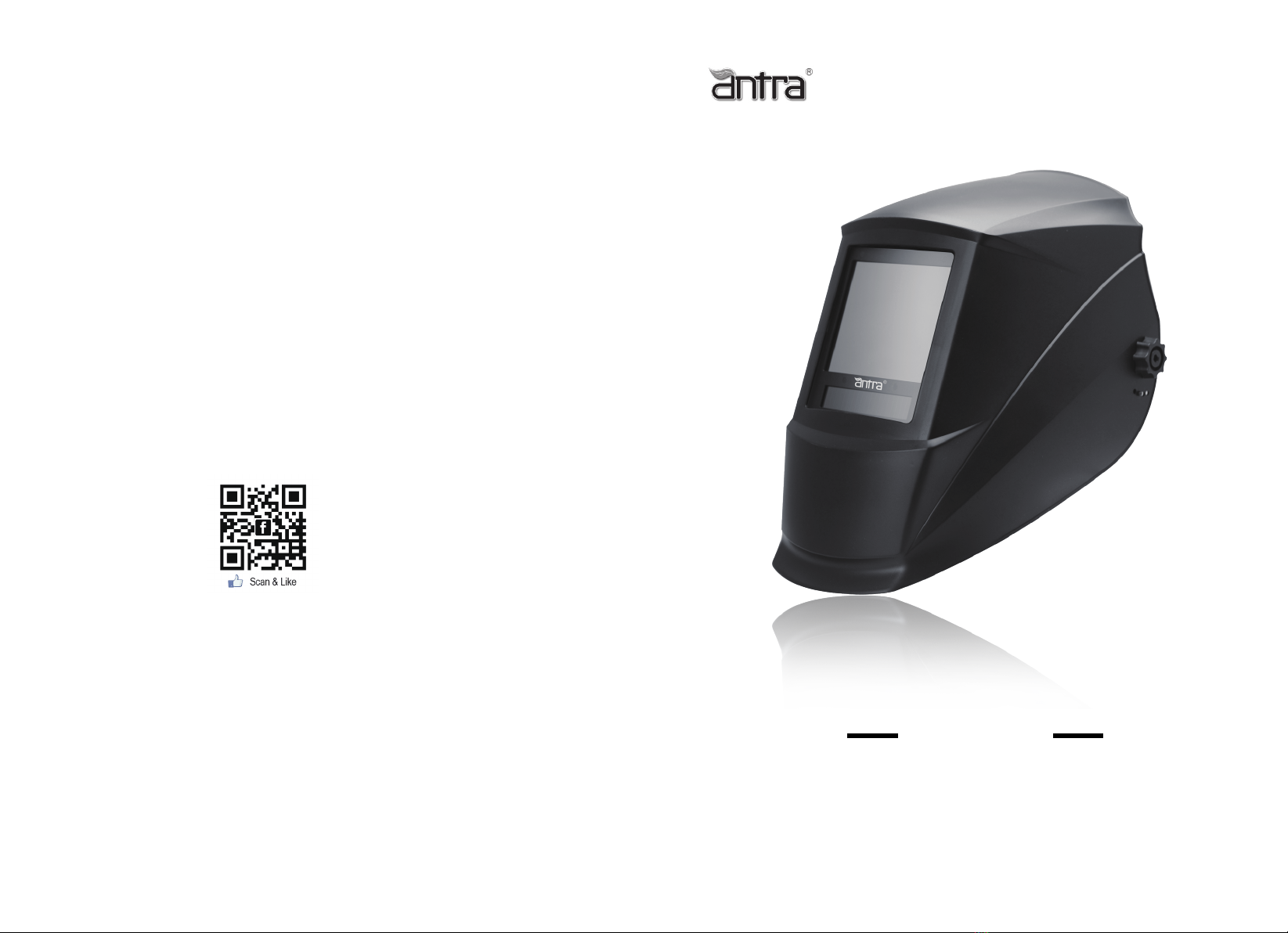
Auto-Darkening Welding Helmet 2022
Digital-Pro SERIES
DP-9
Read and understand this entire instruction manual before attempting to assemble,install, operate
or maintain this tool. Failure to comply with the instructions may result in serious personal injury
and/or property damage!
The following signal words are used to emphasize safety warnings that must be followed when
using this tool:
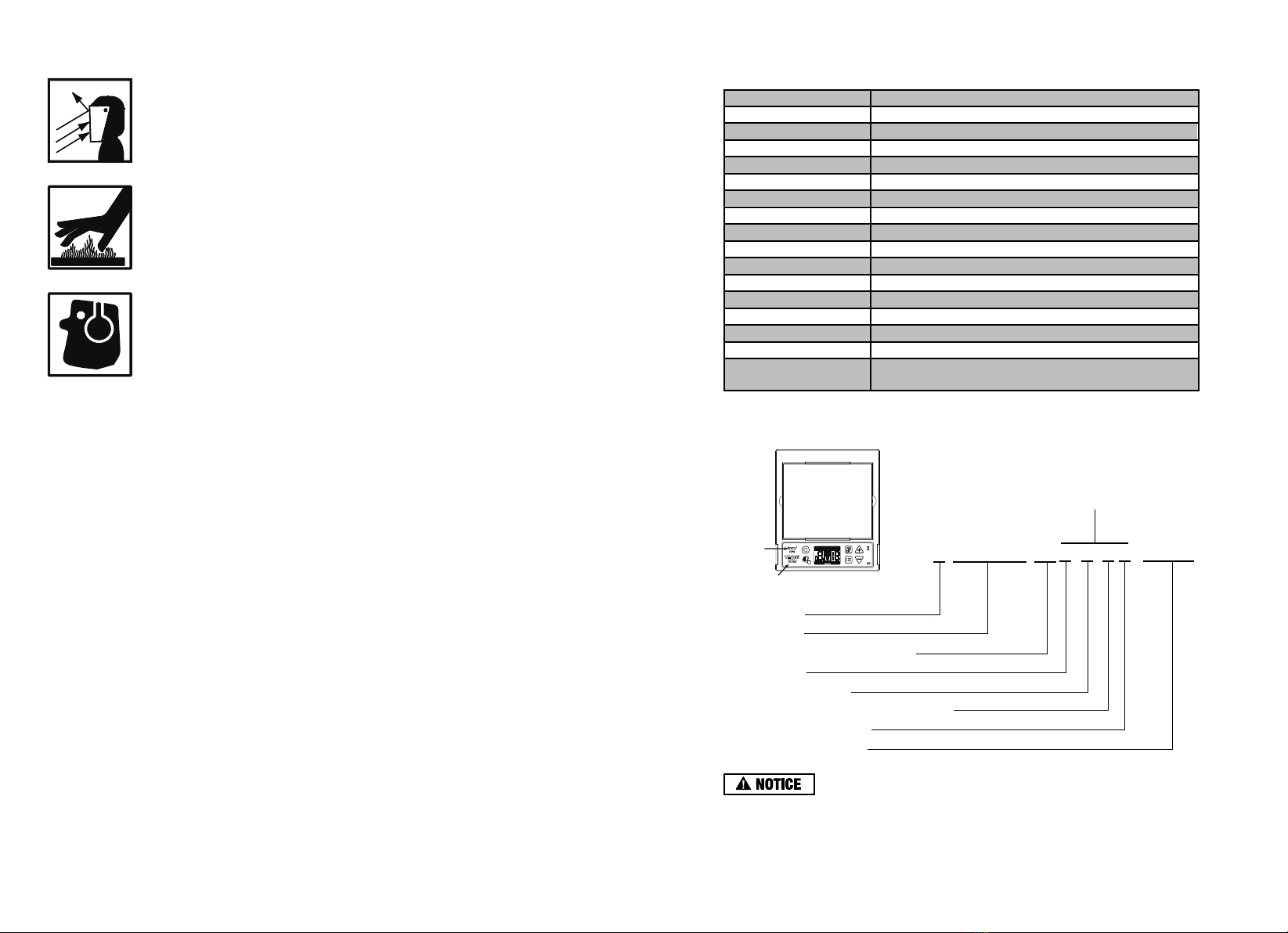
Indicates an imminently hazardous situation that, if not avoided, WILL result
in death or serious injury.
Indicates a potentially hazardous situation that, if not avoided, COULD result
in death or serious injury.
Indicates a potentially hazardous situation that, if not avoided, MAY result in
minor or moderate injury.
Indicates important information, which if not followed, MAY cause damage to
equipment.
IMPORTANT SAFETY INSTRUCTIONS
FUMES AND GASES can be hazardous !
Welding produces fumes and gases that are hazardous to your health.
• Keep your head out of the fumes. Do not breathe in the fumes.
• If inside, ventilate the area and/or use exhaust at the arc to remove welding
fumes and gases.
• If ventilation is poor, use an approved air-supplied respirator.
• Read the manufacturer’s instructions for metals, consumables, coatings, cleaners, and degreasers.
• Do not weld in locations near degreasing cleaning, or spraying operations. The heat and rays of the
arc can react with vapors to form highly toxic and irritating gases.
• Do not weld on coated metals, such as galvanized, lead, or cadmium plated steel, unless the
coating is removed from the weld area, the area is well ventilated, and if necessary, while wearing
an air-supplied respirator.The coatings and any metals containing these elements can give off toxic
fumes if welded.
• Work in a confined space only if it is well ventilated, or while wearing an air-supplied respirator.
Always have a trained watchperson nearby. Welding fumes and gases can displace air and lower
the oxygen level causing injury or death. Be sure the breathing air is safe.
California Proposition 65 Warnings !
• Welding or cutting equipment produces fumes or gases which contain chemicals known to the
State of California to cause birth defects and, in some cases, cancer. (California Health & Safety
Code Section 25249.5 et seq.)
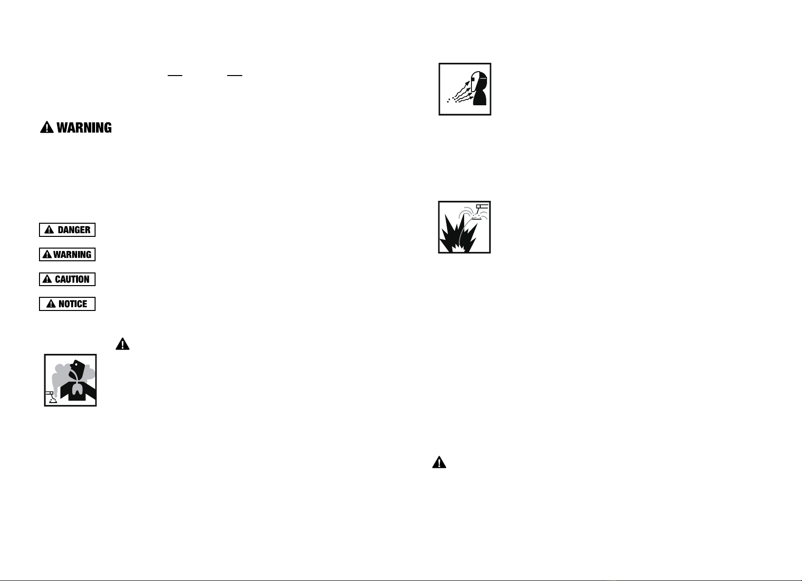
ARC RAYS can burn eyes !
Never look at arc welding without proper eye protection. Arc rays from the
welding process produce intense visible and invisible (ultraviolet and infrared)
rays that can burn eyes and Skin, Hot sparks fly off from the weld and can
burn eyes and skin.
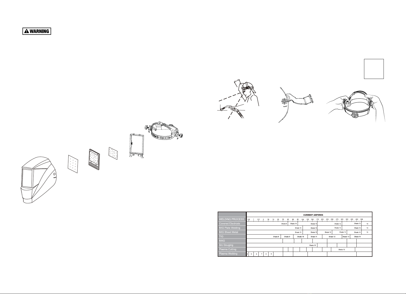
Wear a welding helmet fitted with a proper shade of lens to protect your
face and eyes when welding or watching.
• Wear approved safety glasses with side shields under your helmet.
• Use protective screens or barriers to protect others from flash and glare, warn others in the area
not to watch the arc.
• Wear protective clothing made from durable, flame resistant materials, leather welding gloves
and full foot protection.
WELDING can cause fire or explosion !
Welding on closed containers, such as tanks, drums, or pipes, can cause
them to explode.Sparks can fly off from the welding arc. The flying sparks,
hot work piece, and hot equipment can cause fires and burns, Accidental
contact of electrode to metal objects can cause sparks, explosion,
overheating,or fire. Check and be sure the area is sale before doing any
welding.
• Be alert that welding sparks and hot materials from welding can easily go through small cracks
and openings to adjacent areas.
• Do not weld on closed containers such as tanks, drums, or pipes; unless they are properly
prepared according to AWS F4.1 standards.
• Connect work cable to the work as close to the welding area as practical to prevent welding
current from traveling long, possibly unknown paths and causing electric shock and fire
hazards.
• Never use arc welder to thaw frozen pipes.
• Remove electrode from holder when not in use.
• Wear oil-free protective garments such as leather gloves, heavy shirt, trousers with no cuffs,
high shoes, and a cap.
• Always keep a fire extinguisher readily available and watch for fire.
• Protect yourself and others from flying sparks and hot metal.
• Do not weld where flying sparks can strike flammable material.
• Remove all flammable materials from the welding area. If this is not possible, tightly cover them
with approved covers
• Be aware that welding on a ceiling ,floor, bulkhead, or partition can cause fire on the hidden side.
• Remove any combustibles, such as butane lighters or matches, from yourself and the surroundings
near the welding location before doing any welding.

TECHNICAL SPECIFICATIONS
-3-
-4-
Model
ADF Model
Viewing Area
Cartridge Size
Light State
Dark State
UV/IR Protection
Sensors
Grinding
Battery Type
Sensitivity Control
Solar Cell
Delay Control
TIG Rating
Operation Temperature
Storage Temperature
Standards Compliance
DP-9
X98
98mm x 82mm/3.86" x 3.23"
133mm x 114mm x 9mm/5.24" x 4.5" x 0.35"
Shade DIN 3
DIGITAL 3/5-8/9-14
Permanent Shade DIN 14
Yes
2 x CR 2032 ( Lithium 3 Volt )
DIGITAL(1-9)
Yes
DIGITAL(1-9)/0.1-0.9S
-5°C to +55°C (23° F to 131° F)
-20°C to +70°C (-4° F to 158° F)
4
>2Amp
ANSI Z87.1-2010 & CSA Z94.3-2007
& CE EN379:2009-07 & AS/NZS1338.1-2012
HOT PARTS can cause severe burns !
• Never touch hot parts bare handed.
• Allow adequate cooling period before touching work piece.
NOISE can damage hearing !
• Noise from some processes or equipment can damage hearing.
• Wear approved ear protection if noise level is high.
GENERAL INFORMATION
DP-9 Auto-Darkening Welding Helmet does not protect against severe impact hazards , such as
fractured grinding wheels or abrasive discs,explosive devices or corrosive liquids.Machine
guards or eye splash protection must be used when these hazards are present.
The auto-darkening welding lens are designed for Arc welding or cutting applications.The unit
is suitable for all Arc welding processes such as MIG,MAG,TIG,SMAW,Plasma Arc,and
Carbon Arc.
This auto-darkening welding helmet is not recommended for "overhead" welding applications,
DO NOT use it for laser welding or cutting applications.
In the event of electronic failure, the welder remains protected from UV and IR radiation at shade 14
or higher. (Passive UV/IR filter of 14 or higher).
The auto-darkening welding filter should always be used with original inner and outer cover lenses.
The manufacturer is not responsible for any failure due to modifications to the welding lens or the
use of the lens from any other manufacturer's helmet.
FLYING METAL can injure eyes !
• Wear ANSI approved safety glasses with side shields under your welding helmet.
• Welding, chipping, wire brushing, and grinding cause sparks and flying metal. As welds
cool, they can throw off slag.
MARKING EXPLAINED
3 / 5 -8 / 9-14 AT 1 / 1 / 1 /1 / 379 CE
Light shade
Dark shades
Identification of the manufacturer
Optical class
Diffusion of light class
Variation in luminous transmittance class
Angle dependency class
Number of the standard
Optical Specifications
This is a sample of EN379 marking only. For the product you are
using, please refer to the marking information on the lens.
Standards
Model

PARTS LIST
-5-
-6-
7
• Inspect all parts for signs of wear or damage. Any scratched or cracked parts should be
replaced prior to use.
• When stored in extremely cold temperature, the helmet should be warmed up to
ambient temperature before welding.
• SKIN CONTACT ALLERGIC ALERT! Extra protections must be taken if individuals are
allergic to plastic or other materials that his/her skin may be in contact with when using
this product.
• NEVER place the helmet on a hot surface.
• NEVER open or tamper with the lens cartridge.
1
Helmet Shell
2
Front Cover Lens
3
Cartridge
4
Inner Cover Lens
6
Lens Retaining Frame
Adjustable Headband
5
Lock Switch
1.OPERATION
ADJUST THE WELDING HELMET ACCORDING TO YOUR INDIVIDUAL REQUIREMENTS.
The headband should be adjusted both in circumference and height.
The angle between face and helmet should also be adjusted and recommended to be
10°-12°(Fig.1).
Use the ratcheting knob on the headband to adjust width.
ADJUST HEADBAND PER PERSONAL PREFERENCE.
Loosen or tighten the top strap to adjust headband height, Make sure that the helmet fits firmly
on your head(Fig.3).
Adjust helmet’s headband stop to get desiredviewing angle(Fig.2).
(Fig.1) (Fig.2) (Fig.3)
RECOMMENDED SETTINGS
REFERENCE ANSI Z49.1-2005
9
876 10
Shade 8
Shade 5
Shade 9 Shade 10
Shade 11 Shade 12 Shade 13 Shade 14 Shade 15
Shade 11 Shade 12 Shade 13 Shade 14
Shade 12 Shade 14
Shade 15
Shade 11
Shade 13Shade 12Shade 11Shade 10 Shade 14
SCAN TO WATCH VIDEO

2.MODE SELECTION
Press (Fig.4), the lens is switched between welding, grinding and cutting modes, while
the corresponding settings are displayed according to the value saved.
In the grinding mode, the indicator GRIND is blinking to indicate the lens is in grinding mode,
which will not be responding to welding arc. DO NOT weld or cut using this mode, or eye flash
may occur.
Make sure the lens is on WELD or CUT mode before welding or cutting.
1. Standby Mode (Cut or Weld Mode)
Once the settings are confirmed, the helmet is ready to be used for welding and cutting applications,
the lens will be automatically darkening when an arc is stroked(Fig.4a).
2. Setting Mode
This mode, values of settings can be set, and the change is effective immediately.
The selected setting will be blinking, and the values can be changed(Fig.4b).
3. Lock-Shade Mode
The shade is locked to a certain shade, and the lens is activated and darkened for maximum
1 hour. Shade can be locked and adjusted from 5-14(Fig.4c).
The locked shade will remain upon exiting the shade locking mode, and the last used sensitivity
and delay values are unchanged.
4. Grinding Mode
The lens is on shade 3, and will not be activated by welding arc(Fig.4d).
Grinding Mode will exit automatically 30 minutes after activation, and resume the last used CUT
or WELD settings. DO NOT weld or cut on this mode, or flash will occur.
-7-
(Fig.3a)
Manual OFF, Manual ON
If the lens is shut off manually, it has to be turned on by pressing .
Press Fig.3a to switch the lens between on and off.
Auto OFF, Auto ON
If the helmet is left inactive in low ambient light environment for 30 minutes, it shuts
off automatically. It turns on when enough lights detected by the solar panel.
ALWAYS check power status of the lens before you start to weld! DO NOT start welding if the
power is OFF.
If the helmet is stored in at a place where triggers the lens to dark, manually switch off the
helmet to save power. The lens will draw little to no battery power when it is standby, provided
there is enough ambient lights(200-300lux) on the solar cells. .
(Fig.4)
Working Mode Explained
-8-
Weld Mode Cut Mode
Blinking
The values can be changed.
Fig.4a
Blinking
Blinking
Fig.4b
Grinding ModeLock-Shade Mode
Fig.4c Fig.4d
SCAN TO WATCH VIDEO

NOTE: The (Fig.5)is valid only in the Weld and Cut modes.
Press the (Fig.5)(or ) to enter the setting mode. Setting to enter
is based on the following conditions:
A. If the time when last setting adjustment is done is less than 5 minutes ago, activate
that setting.
B. If the time when last setting adjustment is done is more than 5 minutes, activate
shade setting.
The setting mode is activated, with the activated setting blinking. The setting is ready to
be set by .
In the setting mode, press the to select settings between DELAY, SENSITIVI
TY(SENS), and SHADE. The selected one will be blinking.
The lens exits the setting mode if:
A. Users do not press any keys for more than 5 seconds
B. Press , lens shut off
C. Press to stop blinking and exit the setting mode
D. Press to enter the darkness test and exit the setting mode
DELAY
The delay mode adjusts how quickly the lens goes from dark state back to light state. To change the
delay setting, press (Fig.6), delay can be adjusted from 1 (0.1 seconds) up to 9 (0.9
seconds) .
Use the longer delay setting for higher amperage welds or where the weld pool remains intense
after the arc is extinguished.
Start with a higher value.
Reduce the value as required.
SENSITIVITY
The sensitivity control affects how sensitive the lens is responding to welding arc and/or environ-
ment noise. The higher the value, the easier for the lens to be triggered darkening. Value of 7-8
should be great for most of the applications.
Start with a higher value.
Reduce the value if there is a false triggering.
Increase the value if flash occurs.
Tips :Higher delay value might be required to avoid flashing.
SHADE
Press (Fig.6), shade can be adjusted from 5-8, 9-14(After exit, this shade is saved
as the shade parameter in standby mode.
Start with a higher value.
Reduce as required until the pool is clear and not too bright to eyes.
Tips: ALWAYS check shade the settings before start welding even though this helmet memorizes
the latest used setting. The testing button is a quick way to ensure settings is correct.
(Fig.6) are used to change shade, delay and sensitivity values.
Weld or Cut mode, press , the selected parameter will blink, press the
to adjust the delay sensitivity or shade.
ALWAYS check shade setting on the helmet before start welding even though this helmet
memorized the latest used setting.
-9-
-10-
SETTING SELECTION
(Fig.6)
(Fig.5)
Change of Settings Values

7.MAINTENANCE
Grinding mode will not response to any welding arc, and ALWAYS change the shade
setting back to 5-8/9-14 after grinding.
6.BATTERY DISPLAY
The battery status is displayed in the upper right corner of the screen.When the battery icon
shows an empty status , new batteries are required(Fig.8).
Tips: When the solar panel is blocked, the battery status will show.
REPLACEMENT OF EXTERIOR COVER LENS
Pull up the two lock lugs on the bottom of the filter (Fig.10a), the filter cartridge will pop loose
from the shield.
Detach the cartridge from the shield and put it aside. Remove the old filter cover. Remove the
protect film on the new filter cover(Fig10b). Put the new filter cover back onto the shield.
-11-
-12-
1) Detach the auto darkening lens from the
helmet shield (Refer to REPLACEMENT OF WELDING LENS).
2) Carefully open the battery compartments.
3) Put the new batteries into the compartments (Fig.9).
4)Snap the compartments back into the lens.
5)Install the lens back onto the helmet shield.
Always change both of the batteries when renewing them.
REPLACEMENT OF BATTERIES
NEVER put used batteries into house hold waste.
Please always have used batteries recycled properly.
Press to test the auto darkening feature, the lens will be activated and darkening as per the
shade and delay settings.
Shade lock is to provide a fixed shade as needed. Use to adjust the value from 5-14.
is invalid when the lens is in the grinding mode.
To activate the shade lock feature: Hold for more than 2 seconds to lock the current
shade and enter the lock shade mode.
Only the locked shade is blinking on the screen.
(Fig.10a) (Fig.10b)
(Fig.9)
+
+
(Fig.7) (Fig.8)
5.SHADE TEST/LOCK
SCAN TO WATCH VIDEO
SCAN TO WATCH VIDEO

(Fig.14a) (Fig.14b)
Feed the top edge of the cartridge back to the helmet shield (Fig14a). Push the bottom edge of
the cartridge firmly and pull the lock lugs downwards to completely lock the cartridge (Fig.14b).
Feed the top edge of the cartridge back to filter helmet shield (Fig11a ). Push the bottom edge
of the cartridge firmly and pull the lock lugs downwards to completely lock the cartridge
(Fig.11b).
REPLACEMENT OF INNER COVER FILTER
Detach the auto darkening filter from the helmet shield (Refer to REPLACEMENT OF
WELDING FILTER).
Lift up one edge of the inner cover filter and pull the cover filter away from the
filter(Fig.12a).
Remove protective film on the new inner filter cover, feed one side of the filter cover (Fig.12b)
onto filter retaining slots on the filter then push it slightly all the way until the whole filter cover
-13-
-14-
(Fig.12a)
(Fig.11a) (Fig.11b)
Ensure the front cover filter is mounted before using and the protective film on the filter cover
is removed.
Ensure that the filter is clean and there is no dirt or spatter covering the 4 sensors at the front
of the filter cartridge.
REPLACEMENT OF WELDING LENS
Pull up the two lock lugs on the bottom of the filter (Fig.13a), the filter cartridge will pop loose
from the shield.
Detach the cartridge from the shield.
Hold the cartridge with both hands, with solar cell side up, lift top edge of the cartridge using
thumbs to loose the filter from the cartridge. Try to pop up the filter from underneath using other
fingers while thumb is pushing the cartridge edge upwards (Fig.13b). Take the old filter out
from the cartridge.
Feed the bottom of the new filter on the the bottom side of the cartridge.
Push gently on the top side of the filter, it will snap into the cartridge.
(Fig.13b)(Fig.13a)
(Fig.12b)

-15-
-16-
8.INSPECTION
1. Carefully inspect your Auto-Darkening Welding lens regularly.
2. Cracked, pitted or scratched lens glass or cover lenses reduced vision will seriously impair
protection.
3. Worn parts should be replaced immediately to avoid injury to the eyes.
CLEANING AND DISINFECTION
Clean the helmet with mild soap and lukewarm water.
Clean the welding lens with a clean lint-free tissue or cloth.
DO NOT immerse in water.
DO NOT use solvents.
TROUBLE SHOOTING
AUTO DARKENING LENS DOES NOT DARKEN OR FLICKER
- Check the lens cover for dirt and spatter that may be blocking the arc sensors.
- The sensors are dirty, wipe them clean with a soft lint-free cloth.
- Check the sensitivity setting recommendations and increase the sensitivity if possible.
- Increasing lens delay 0.1-0.3 second may also reduce flickering.
- Check batteries and verify that they are in good condition and installed properly.
- Battery terminals and the contact surface of the lens are dirty or oxidized(clean both) .
- Shade adjustment knob is on "GRIND" position, set helmet on “WELD” and/or proper shade
from “5-13”.
THE LENS STAYS DARK AFTER THE WELD ARC IS EXTINGUISHED, OR THE
AUTO-LENS STAYS DARK WHEN NO ARC IS PRESENT.
- Fine-tune the sensitivity setting in small increments. In extreme light conditions, it may be
necessary to reduce the surrounding light levels.
SLOW SWITCHING
- The operating temperature is too low, don’t use at temperatures of below -5 ℃(+23℉).
POOR VISION
- The cover lens and the lens cartridge is dirty or damaged, clean the dirty components and
replace the damaged ones.
- Ensure ambient light is not too low.
- Ensure the shade number is correct and adjust accordingly.
IRREGULAR DARKENING
- Headband has been set unevenly so the distance between the eyes and the lens is different
from the left to the right side.
If the described malfunctions cannot be solved, stop using the helmet immediately and contact
the nearest distributor.
WARRANTY
We warrants to the purchaser that the product will be free from defects in material and
workmanship for the period of one year from the date of purchase. Our sole obligation under
this warranty is limited to replacement or repairs.
This warranty does not cover product malfunctions or damages, which result from the product
being tampered, misused or abused. We are not responsible for any indirect damages or injury,
which arises out of the use of the product.
We recommend a use for a period of 3 years, but no longer than 5 years. The duration of use
depends on various factors such as use, cleaning, storage and maintenance.
Distributed by
AntecTrade & IT Consulting Inc.
106 Ferrier St.
Markham,ON L3R 2Z5
Canada
This manual suits for next models
1
Table of contents
Other Antra Welding Accessories manuals
Popular Welding Accessories manuals by other brands

Kemper
Kemper oxikit 555C user manual

Chicago Electric
Chicago Electric 61610 Owner's manual & safety instructions

Abicor Binzel
Abicor Binzel ABIROB operating instructions

Miller Electric
Miller Electric DS-2 owner's manual

Lincoln Electric
Lincoln Electric CAN-F30 user manual

aquatherm
aquatherm 50336 Operation and maintenance manual