ANTTI Plug&Dry User manual

Installation and
Operating Instructions
03-2020
ANTTI GRAIN DRYER
Antti Plug&Dry
408116 (en)
ANTTI-TEOLLISUUS OY
Koskentie 89
FI-25340 Kanunki, Salo
Tel. +358 2 774 4700
E-mail: antti@antti-teollisuus.
www.antti-teollisuus.

ANTTI PLUG&DRY ................................................................................................................................................ 4
SELECTING LOCATION FOR THE DRYER.......................................................................................................... 4
FOUNDATION ........................................................................................................................................................ 4
THE SPACE REQUIRED FOR THE INSTALLATION............................................................................................. 5
PRESENTATION OF THE MACHINE .................................................................................................................... 5
SAFETY.................................................................................................................................................................. 6
INSTALLATION OF THE ANTTI PLUG&DRY ........................................................................................................ 6
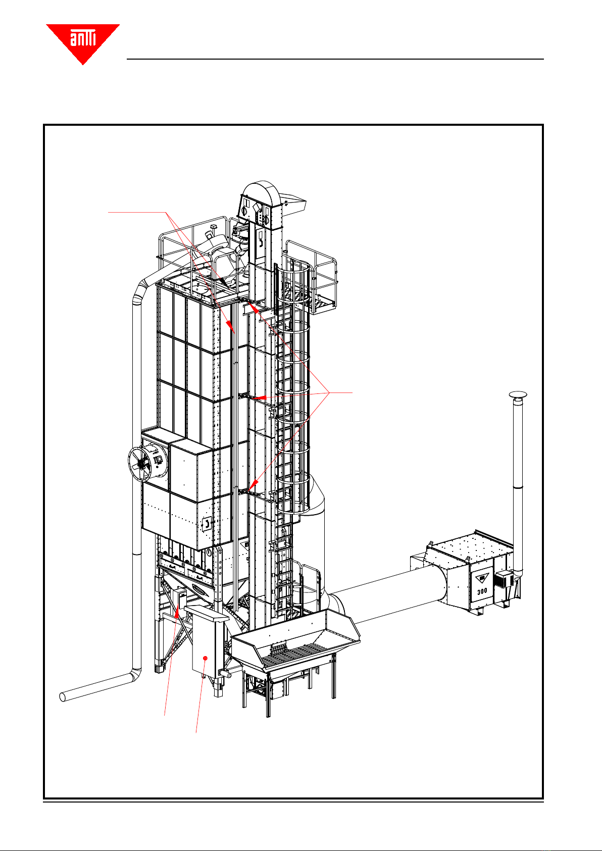
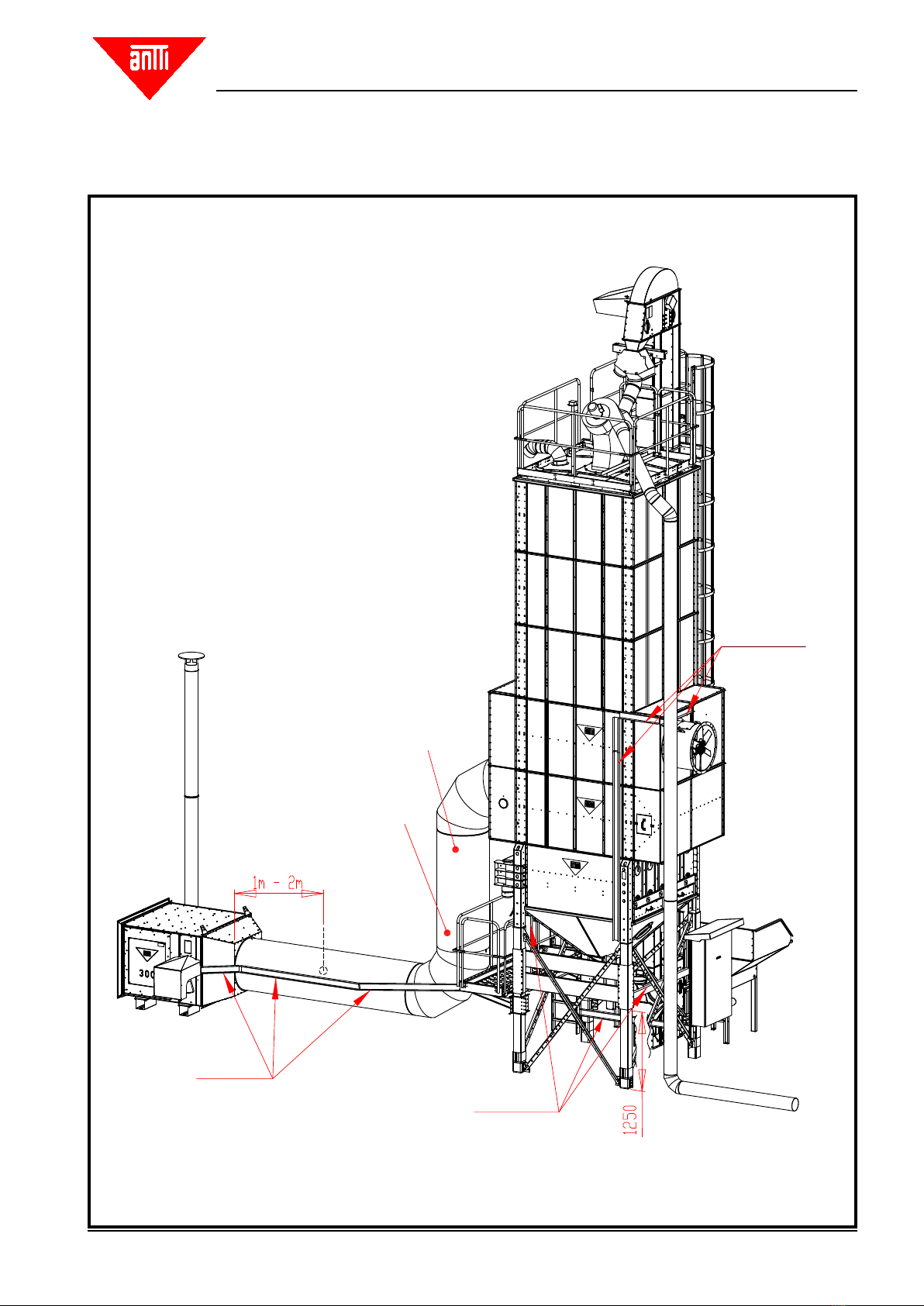
Principle drawings of dierent dryer types with accessories .................................................................................. 8
Installing the electric cabinet and the bracket for the frequency transformer ...................................................... 11
Principle drawing of the cable routing................................................................................................................... 12
Unit-specic cabling ............................................................................................................................................. 13
Example of connector IDs .................................................................................................................................... 14
Electric installations.............................................................................................................................................. 15
Installation ............................................................................................................................................................ 16
Installing the LTM thermostat ............................................................................................................................... 16
Installing the temperature transmitter and the re thermostat in the axial blower ................................................ 17
Installing the vacuum sensor................................................................................................................................ 19
Installing the upper limit sensor (Capacitive, adjustable) ..................................................................................... 20
Installing the temperature transmitter in the duct ................................................................................................. 21
Installing the re thermostat in the duct................................................................................................................ 23
Piping the heaters with a grain pocket.................................................................................................................. 31
Dimensioning of the basic parts viewed from the side ......................................................................................... 32
Dimensioning of the basic parts with a small intake pit viewed from above......................................................... 33
Principle dimensioning drawings for the 10 m³ and 17m³ intake pits ................................................................... 34
Dimensioning of the intake pit to be used with a chain conveyor......................................................................... 35
Installing the base and the legs............................................................................................................................ 36
Sections, air channel ends ................................................................................................................................... 36
Top tanks and cover with handrails ...................................................................................................................... 36
Installing the elevator and the ladder.................................................................................................................... 37
Bolt-assembled hopper 10m³ / 17m³ .................................................................................................................... 37
The intake pit with Skandia conveyor................................................................................................................... 37
Wire control of the 3-way divider .......................................................................................................................... 38
Fuel pipes............................................................................................................................................................. 47
Installing the debris piping for the pre-cleaner...................................................................................................... 47
STARTING UP...................................................................................................................................................... 48
Elevator ................................................................................................................................................................ 48
Pre-cleaner........................................................................................................................................................... 48
Feeder ................................................................................................................................................................. 49
Blower................................................................................................................................................................... 49
Burner................................................................................................................................................................... 49
LTM thermostat..................................................................................................................................................... 49
CONTENTS
Translation of original

Antti-Teollisuus Oy 3 408116 03-2020
THERMAL INSULATION ...................................................................................................................................... 50
OPERATION INSTRUCTIONS FOR THE DRYER MACHINERY (detailed instructions)..................................... 50
Initial adjustment and checking of the dryer ......................................................................................................... 50
Drying ................................................................................................................................................................... 50
Cooling ................................................................................................................................................................. 51
DRYING TECHNICS ............................................................................................................................................ 52
MAINTENANCE AND OPERATING ADJUSTMENTS.......................................................................................... 53
ECONOMICAL DRYING....................................................................................................................................... 54
POSSIBLE MALFUNCTIONS .............................................................................................................................. 57
SERVICE AND WINTER MAINTENANCE .......................................................................................................... 57
GUARANTEE ....................................................................................................................................................... 58
EU Declaration of Conformity............................................................................................................................... 59

Antti-Teollisuus Oy 4 408116 03-2020
ANTTI PLUG&DRY
Read the Installation and Instruction Manual carefully before installing the machine and putting it into operation.
SELECTING LOCATION FOR THE DRYER
Locate the grain dryer as a part of the farm's centre of operations, taking into account possible trac, noise and
dust problems. Construct the roads in a manner enabling them to be tracked with a full trailer round the year.
If possible, locate the heater on the facade side of the building. When selecting location for the heater, observe
in particular that it requires large amounts of clean air. The suction opening of the heater must be located as far
from the outlet air pipes as possible, on the other side of the building. If you have doubts concerning the location,
negotiate in advance with the local building and road authorities, and the re chief.
The distance from the grain dryer to the land of the neighbour shall be at minimum 15 m, to the neighbouring
building 20 m, to your own residential building15 m, and to an outbuilding 12 m. (The minimum distance to your
own buildings may vary from municipality to municipality, depending on how the new regulations are being locally
interpreted). For dryers of category P2, the required distances may be shorter. Under certain conditions, a package
dryer may fall into category P2. Consult the local re chief or building supervisor for detailed instructions.
FOUNDATION
GROUND PRESSURE
When selecting suitable founding method for your dryer, apply the following base values for dierent soil types:
Moraine 0,4 – 0,8 MN/m2
Gravel 0,2 – 0,6 MN/m2
Sand 0,15 – 0,5 MN/m2
Fine sand 0,1 – 0,4 MN/m2
Clay and ne silt:
- soft (easy to work) 0,025 MN/m2
- tough (hard to work) 0,050 MN/m2
- solid (extremely hard to work) 0,1 MN/m2
If you consider that the load-bearing capacity of the soil is dicult to determine, assign a specialist or order a ground
survey. It is often a good idea to establish the form of the rock by means of a ground survey or a test excavation.
Typically, the ground pressure caused by a dryer is 0.5–2.0 kg/cm2 when the foundation is of raft type.

Antti-Teollisuus Oy 5 408116 03-2020
THE SPACE REQUIRED FOR THE INSTALLATION
The minimum requirement is that the foundation drawings are being followed.
In addition, you must take into account the space required for the installation, and the load-bearing capacity of the
soil under the mobile crane.
The goods to be transported can be over 3 metres wide and fairly long. Therefore, the access to the foundation of
the dryer must be unobstructed, and sucient space must be reserved for turning the vehicles.
For the erection of the dryer, the mobile crane must be provided with unobstructed access near the installation
site and a suciently sturdy standing base. There must not be any aerial electric or telephone lines at the erection
site, within the reach of the mobile crane.
Instruction manual for erecting and operating the machine
This manual is intended for professional farmers. The use of the machine requires normal skills and general
knowledge of farming.
Grain dryer type
This manual deals with installation and use of ANTTI PLUG&DRY.
PRESENTATION OF THE MACHINE
- Grain dryers are intended for drying of grain and seeds.
- The drying process comprises four phases:
1. During the lling phase, the elevator transfers the grain from the lling hopper of the dryer into the dryer.
2. During the drying phase, the grain circulates inside the dryer, and simultaneously, hot air is being sucked
through the grain layers.
3. During the cooling phase, the grain is being circulated inside the dryer, and cold outside air is being sucked
through the grain layers.
4. The ready-dried and cooled material is transferred by means of an elevator to the storage or to be loaded.
The dryer is delivered, as ordered, as pre-assembled units or in parts, and the nal assembly shall take place at
the installation site.

Antti-Teollisuus Oy 6 408116 03-2020
- The pedestal of the dryer comprises the dryer base and the feeder. The drying sections are installed on top
of the base.
- The drying unit comprises drying sections with triangular air ducts. The top tanks are stacked on top of the
drying unit.
- The volume of the dryer depends on the number of the sections and the top tanks, being installed one on top
the other.
- In addition to the main parts itemised above, the delivery also includes a number of smaller parts, the instal-
lation of which is described more in detail later in these instructions.
In dryers, the most signicant source of noise is the axial blower/axial blowers. Refer to the blower manual for
detailed information.
SAFETY
The dryer base has moving feeder parts that can cause an injury, if all the cover plates and hatches are
not properly closed, while the machine is in operation!
NOTE!
Before opening or closing the bottom troughs, ensure that the inspection and cleaning hatches in the
dryer base are closed.
Follow the local instructions for occupational safety.
INSTALLATION OF THE ANTTI PLUG&DRY
Refer to the erecting instructions 408076 for the dryer for installation of the sections and the other basic components.
These instructions deal with the installation of the Plug&Dry dryer's model-specic components.
The installation work of the dryer requires precision. The work must be carried out on various levels, even at high
elevations. Therefore, in addition to good installation skills, the work requires proper scaolding/use of aerial work
platforms and observation of all the safety issues. Especially, the dryer base and the sections are heavy. Lifting
them requires suciently powerful machinery.
Pre-connected wiring is used for installations in the electric centre. Before starting the use, make sure that all the
electric appliances are in order!

Antti-Teollisuus Oy 7 408116 03-2020
Weight of the dryer's components:
2W 3W 4W
Base 725 kg 900 kg 1320 kg
Section (2 pcs, without air channel ends) 1080-1190 kg 1520-1635 kg 1960-2115 kg
Top section 220 kg 280 kg 355 kg
Top section with cover and handrails 400 kg 520 kg 655 kg
Please observe, when lifting the heavy components of the dryer:
- use all the lifting lugs on the components
- use the lifting lugs and a bracing when lifting the ready-assembled top tank
- ensure that the lifting hooks stay in position in the lugs, and that the crane being used is suciently powerful
- never go under or too near the components to be lifted
- the crane must be able to lower the component to be lifted slowly and precisely into position
- reserve 3–5 tools that can be used as guide pins such as, for example, pin punches of 5–8 mm in diameter
Provide all the horizontal seams with sealing band.
Note! If you wish to stack several sections, and lift them on top of the base in one go, use the separate lifting lugs
(501010). Refer to the erecting instructions 408076 for detailed instructions. Attach the lifting lug by eight M8
bolts. Brace the lugs by xing battens of 50x100 by the two holes to support the lugs so that the section end will
not bend. Use the same lugs for lifting the top tanks.
The dryer can be assembled from larger sub-assemblies. All the drying sections and the top tanks can be lifted
into place using the robust lugs on the top. The maximum load, allowed to be lifted is 6,750 kg An example: the
top tanks and the top tank cover with handrails can be assembled while the section is still on the ground. Tighten
all the bolts – use M10 bolts for xing the vertical supports. Lift this large sub-assembly on top of the base or the
lower-lying sections.
NOTE!
The total weight of the sub-assembly is several tonnes, so a heavy crane is required. Verify the load-bearing ca-
pacity of the soil, before the lifting.

Antti-Teollisuus Oy 8 408116 03-2020
23MF2-ohje kuvaan_1.pdf
Principle drawings of dierent dryer types with accessories
Elevator support
Principle drawing of the assembly
Cable ladder
Frequency transformer
Control System
STANDARD POSITION

Antti-Teollisuus Oy 9 408116 03-2020
23MF2-ohje kuvaan_2.pdf
Temperature sensor
Gas-fuelled heaters, direct driven:
LTM Vacuum sensor
Cable ladder
LTM
Vacuum sensor
Cable ladder
Cable ladder,
keep the wiring o hot
surfaces

Antti-Teollisuus Oy 10 408116 03-2020

Antti-Teollisuus Oy 11 408116 03-2020
Installing the electric cabinet and the bracket for the frequency transformer

Antti-Teollisuus Oy 12 408116 03-2020
E1, E2
FD1, FD2 (4W)
Laitevärit
yellow
blue
red
green
black
F1, F2, F3…
red Fx_TZ_CX1
red TE2_CX1
P1
green LS1
B1
black LTM_CX1
black PS_CX1
black TE1_CX1
yellow
green
red
blue
yellow
black
Unit-specic colours:
Principle drawing of the cable routing
Feeder
Elevator
Axial blower
Fire thermostat
Outlet temperature
sensor
Precleaner
Limit sensor
Burner
LTM
Differential pressure
switch
Inlet temperature
sensor
The outlet temperature sensor TE2_CX1 shall be installed in the blower on the left
side. If there are blowers in more than just one row, the outlet temperature sensor
shall be installed in the one lying lowest on the left-hand side.
Cable ladder

Antti-Teollisuus Oy 13 408116 03-2020
yellow
green
red
yellow
black
Unit-specic cabling
Cable ladder

Antti-Teollisuus Oy 14 408116 03-2020
Example of connector IDs
The cables shall be tied to the cable ladder,
making sure that no loading, resulting e.g. from
the weight of the cables, will be subjected to
the connectors or the connecting boxes of the
motors.
The location of the elevator with respect to
the electric cabinet, the default location of the
electric cabinet.

Antti-Teollisuus Oy 15 408116 03-2020
Electric installations
After having assembled the entire machinery, install last the cable ladders and the wiring. Install the cable ladders
in full length from the bottom to the top. Cut o the uppermost cable ladder at the height of the dryer's top using
side-cutting pliers or an angle grinder.
The conductors for the following units are routed from the upper part of the dryer:
- Elevator
- Pre-cleaner
- Level guard
If the electric cabinet has been agreed to be relocated from its standard location, when placing the order, the cables
will be shipped with the specied additional length.
Additional length refers to the total length of the cable. The length cannot be altered after placing the order. The
actual distance of the electric cabinet from its default location depends on the route selected for the cable.
Fold the possible excess length of the cable on the cable ladder or cut the cable and reconnect it using a branch box.
If you will place the cabinet further away than agreed, extend the cables accordingly using a branch box.
Route the conductors to the electric centre, and connect them to the inlet as marked in the conductor Attach the
conductors to the cable ladders using cable ties. On vertical ladder the tying points shall be 50 cm apart, and on
horizontal ladder, 100 cm apart. You can "hide" the excess length of the conductor by folding it inside the trough.
Install the pressure dierence sensor, the PTC sensor and the LTM thermostat in the air pipe coming from the
heater. Provide the axial blower on the outlet side with a PTC sensor and a re thermostat.
- The electric conductors must be at a distance of at least 50 mm from the surface of the heating pipe to avoid
the risk of overheating.
The electricity supply to the grain dryer – like to any other building on the farm – must be protected with a fault
current switch
in accordance with the valid legislation.
It is recommended that the electricity supply be protected by means of proper overvoltage protection.

Antti-Teollisuus Oy 16 408116 03-2020
Installation
Installing the LTM thermostat
The LTM thermostat is a double-thermostat, which includes a temperature
limiter and the after-cooling system for the heater.
The LTM thermostat is installed in the inlet air pipe, at a distance of 0.5–2
m from the heater. Drill a hole of 19 mm for the thermostat in the pipe,
press the thermostat into the hole and x it with screws.
SEE THE DRAWING ON PAGE 9 FOR THE INSTALLATION PLACE
Set the temperature limiter 20 °C above the maximum allowed operating
temperature of the heater. For example: if the maximum allowed operating
temperature of the heater is100 °C, set the temperature limiter to 120 °C.
The after-cooling system shall always be set to 45 °C.
A – Temperature limiter (LIMIT)
B – After-cooling (FAN)

Antti-Teollisuus Oy 17 408116 03-2020
Installing the temperature transmitter and the re thermostat in the axial blower
Correct installation of the blower and direction of rotation of the impeller are absolutely crucial. The arrows indica-
ting the direction of the airow and the direction of rotation are punched in the nameplate and the arrow indicating
the direction of rotation is punched in the impeller blades.
The re thermostat and the outlet temperature sensor shall be installed in their designated installation points as
shown in the adjacent drawings
Installation of the temperature transmitter installation of the tire thermostat
Suction bell
Direction of rotation
Temperature sensor
Fire termostat
Backdraft damper (optional)
Check the direction of rotation of the dryer heater fan
and the direction of airow before start-up.
Airow direction

Antti-Teollisuus Oy 18 408116 03-2020

Antti-Teollisuus Oy 19 408116 03-2020
Installing the vacuum sensor
Fix the sensor unit (1) on the wall in an upright position, as shown in the drawing.
Drill an 8 mm hole in the air pipe for the lead-through sleeve Fix the lead-through sleeve using self-tapping screws
(4). Do not forget to place the rubber washer (3) between the pipe and the lead-through sleeve.
Connect the PVC hose to the "upper" connector (5) of the sensor unit; the cover plug of the connector, closest to
the wall, must be removed. Connect the other end of the hose to the lead-through sleeve.
Connect the cable, using the Abico-connectors included in the delivery, to the terminals 2 and 3 (6), as shown in
the wiring diagram.
The pressure is adjusted by means of the disc, located in the centre of the sensor unit. Set the sensor to such a
pressure value, that the positions 2–3 of the change-over contact will be switched on, even if the air adjuster plate
is in its minimum position.
If the change-over switch is not switched on, the oil burner will not start.

Antti-Teollisuus Oy 20 408116 03-2020
Installing the upper limit sensor
(Capacitive, adjustable)
The delivery of the dryer machinery includes a capacitive level guard with an adjustable rod.
Installation dimensions for the upper limit sensor are presented in the drawing below. Seal the joint between the
bracket and the cover using mastic glue. Install the sensor suciently low to prevent the elevator from congesting
during the rst times of use. The correct height of the sensor is about 60 cm from the top.
Follow the dryer's lling rate during the rst lling and drying rounds. You must search out the correct height for
the upper limit sensor, because in practice, it varies. Observe that the grain mass expands in the beginning of the
drying phase. Therefore, some space must be reserved for the pre-cleaner. Fix the height position of the sensor
using the wing screw.
Over time, the sensor's head may get dirty and start transmitting wrong data. Due to the above reason, the sensor
head should be cleaned from time to time.
Table of contents
Other ANTTI Farm Equipment manuals
Popular Farm Equipment manuals by other brands

XAG
XAG 3 Pro user manual

Johnny's Selected Seeds
Johnny's Selected Seeds 9414 instruction manual

nardi
nardi SUNSTORM SFH600 Use and maintenance manual

Claas
Claas 930 Information and Basic Field Settings

Maschio
Maschio GASPARDO CIRO E USE AND MAINTENANCE - OPERATOR'S MANUAL

Hoegger Home Farm Products
Hoegger Home Farm Products Milking System Training Series manual