Antti-Teollisuus Oy 10 408102 06-2010
Vacboost WM09
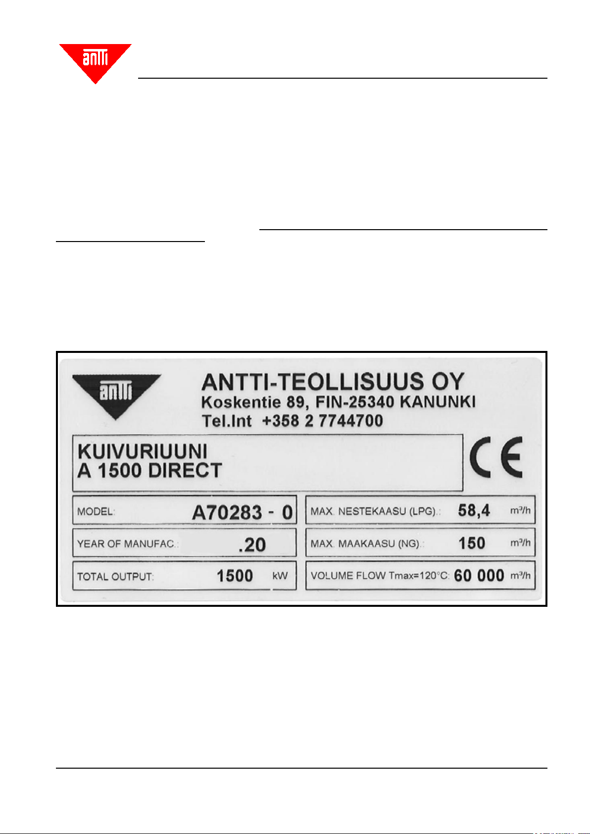
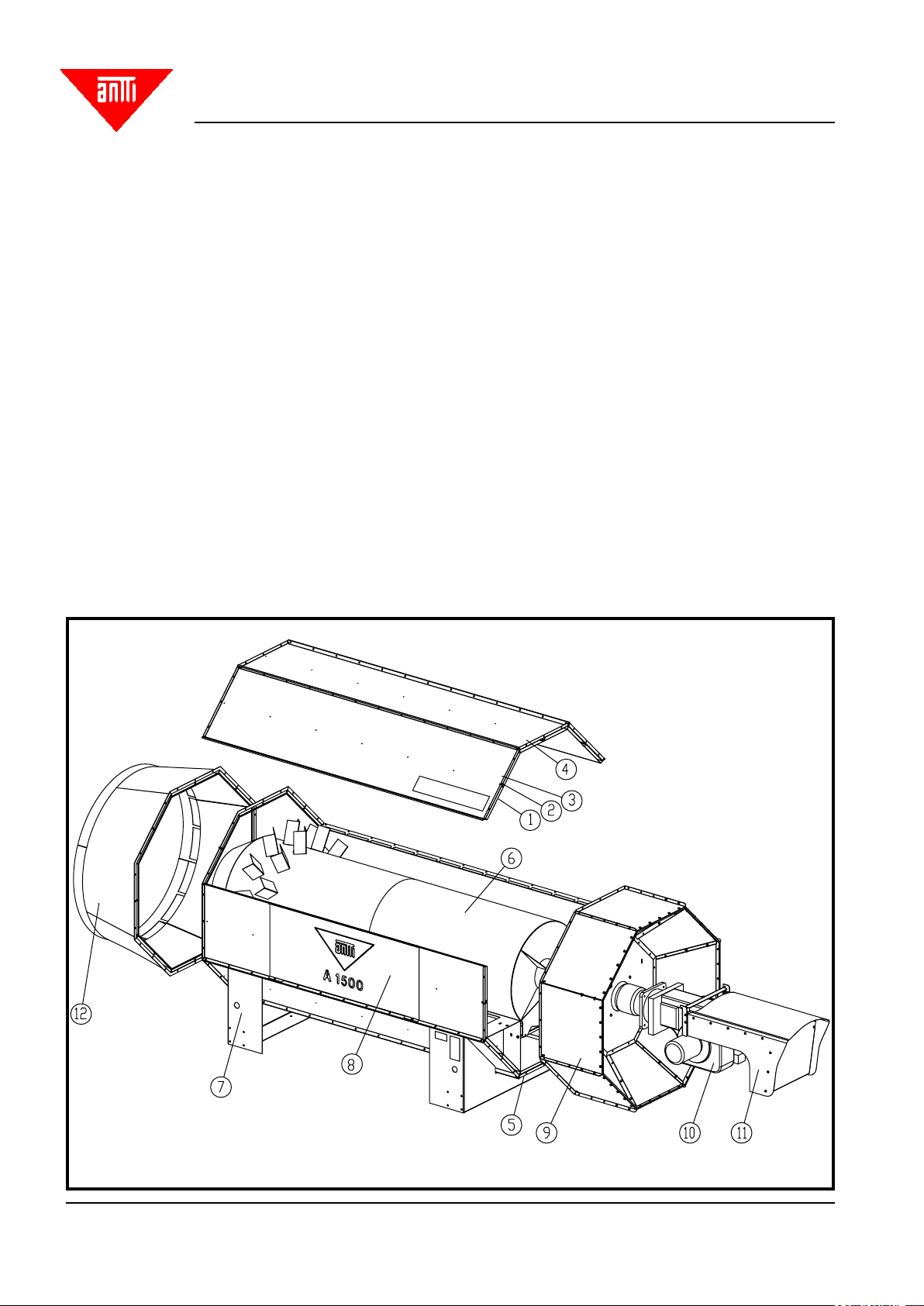
Dryer Heater
Electric installation
Assign an authorised electrician to all electrical installation work, including installation of thermostats and connec-
tions to the control centre of the dryer! The electrician shall issue a certicate of the installation work in writing.
Installation instructions of the thermostats and sensors for the electrician (see also Fig. “Location of the thermo-
stats in the dryer”):
- On the inlet side, the thermostats and the sensor shall be installed in the air duct inside the building (if there is
a building) in a straight part of the duct (not near the curves) where the airow is smooth. Furthermore, there
must not be a direct line of vision from the sensors to the rear part of the combustion chamber so that the red
glow from the combustion chamber could interfere with the values measured by the thermostats.
If the sensors transmit wrong information, moving one of them to the other side of the duct may help. Hot and
cool air have probably not yet mixed completely at this stage. Another option is to measure the true temperature
of the drying air and raise the setting of the thermostats from their rated values by the dierence between the
true and the wrong measurement results (applies to the LTM thermostat).
- If there are more than just one blower, the thermostats and the sensors on the outlet side shall be installed in
the lower air duct (as required, the upper blower can be disabled).
- If the heater is located in a heater room, the door to the room must be equipped with a limit switch. The purpose
of the limit switch is to ensure sucient airow through the heater.
- The electric conductors must be at a distance of at least 50 mm from the surface of the heating pipe so as to
avoid risk of overheating.
- Carry out the electric installations of the heater in accordance with the wiring diagrams for the electric centre.
Thermostats and their initial settings:
- Temperature regulator, LTM -thermostat. If you are using the Logic Control Centre, there is no need for a sepa-
rate LTM thermostat. If the maximum drying temperature of 120°C is applied, the “limit” value for the thermostat
must be raised to 150°C, so that the burner will switch o if this temperature for any reason would be attained
(in case of malfunction). The standard setting is 110°C and it is intended for standard positive pressure heaters.
The thermostat in question also prevents the blowers from stopping until the drying air temperature has dropped
to 45°C, i.e. to the “fan” value of the thermostat. There are two discs inside the thermostat for adjusting the
“fan” and “limit” settings. The sticker under the screwed lock shows that the terminal block of system 1 are for
setting of “limit” etc. Drill a D19 mm hole in the air inlet pipe for the capillary pipe of the thermostat, and insert
this pipe inside the air duct and x it by its holder on the pipe using, for example, self-tapping screws.
- Sensor for drying air temperature (sensor for the 2nd ame). Drill a 10.5 mm hole in the inlet air pipe. Thread
in the thermostat sensor into the D8x1 nylon pipe, L=150 mm, so that about half of the sensor's tip remains
visible. Place a lead-through rubber ring on the nylon pipe and x the assembly to the pipe by means of the
lead-through rubber ring. The sensor must be inserted about 100 mm into the air pipe. See picture on the next
page.
- The purpose of the pressure dierence sensor is to monitor that the air ows through the heater and does not
take any other route of lower resistance. Therefore, it must not be installed anywhere else than in the inlet air
pipe after the heater.