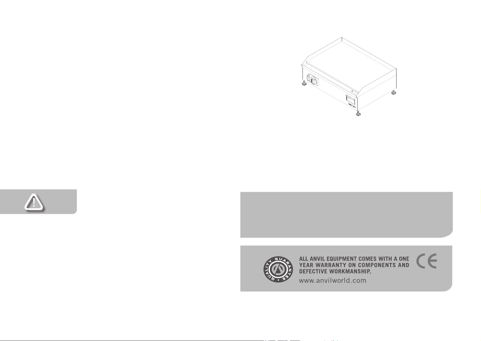
Anvil FTA0400 R01 Owner's manual

NB:
REGISTER ON-LINE TODAY
Register your warranty on-line now at www.anvilworld.com
NO WEB ACCESS
If you do not have access to the web. Kindly register by completing
the warranty registration form and fax it to the anvil ofce in the
country of purchase.
Failure to do so will invalidate your warranty.
FLAT TOP GRILLER ELECTRIC
INSTALLATION OPERATION AND CARE OF
FLAT TOP GRILLER ELECTRIC
MODELS: FTA0400 R01/FTA0400-120 R01/FTA3400 R01
FTA4400 R01/FTA4400-120 R01/FTA2600 R01
FTA0600 R01/FTA1600 R01/FTA3600 R01
FTA0900 R01/FTA4600 R01
4-INS-FTA0400R01
LIMITED WARRANTY
All equipment which is sold under ANVIL trademark and used for
commercial purposes is warranted against defects in materials and
workmanship. The warranty runs for one year from the date of origi-
nal installation and is for the benet of the original purchaser only.
All other Warranties ,expressed or implied , statutory or otherwise,
including without limitations any implied Warranty of Merchantability
or tness for purpose are excluded .The Seller shall in no event be
liable for direct,indirect or consequential damages in connection with
ANVIL commercial products.
The Sellers obligation under this Warranty is limited to the re-
pair of defects without charge. Defective units must be taken or
shipped,transportation charges prepaid,to ANVIL.
This Warranty is not effective if damage occurs because of
accident,carelessness,improper installation,lack of proper set-
up,supervision when required or if the equipment is installed or
operated in any manner contrary to the installation and operating
instructions. In these cases,repairs will be made at a reasonable
cost. Work performed by unauthorized personnel or unauthorized
service agencies using non Anvil spares voids this Warranty.

GENERAL INSTALLATION AND OPERATION INSTRUCTIONS
THESE INSTRUCTIONS MUST BE FOLLOWED FOR US TO
GUARANTEE OUR FULL SUPPORT OF YOUR CLAIM FOR
PROTECTING AGAINST LOSS FROM CONCEALED DAMAGE.
THE FORM FOR FILING SUCH A CLAIM WILL BE PROVIDED
BY THE CARRIER.
UNPACKING
Unpack the product and check for any damage incurred during
transit. This should be reported to the responsible carrier, railway or
postal authority, and a request for a damage report should be made.
1. Before using the griller, turn the knob to maximum temperature.
Allow the griller to burn in for +/-30 minutes. You will notice smoke
appearing due to the protective coatings burning in. This is normal.
2. After the burning in period has lapsed, turn the temperature con-
trol knob down to the desired operating temperature. Grease
plates generously with butter or oil.
3. Never allow excess fat or oil to build up as this will result in the
building up carbon on the plates. This can be removed with a
scraper or grill brick.
4. The griller is provided with adjustable feet to enable the slope of
the griller plate to be set towards the fat drain tray.
Part
No.
1 BODY ASSEMBLY
2 CONTROL PANEL FACIA
3 PILOT LIGHT
4 CONTROL KNOB
5 BEZEL
6 CONTROL FACIA PANEL INSERT
7 GRILLER THERMOSTAT
8 GRILLER FAT TRAY
9 ANVIL AXIS LOGO
10 ELEMENT CLAMP BAR
11 PROBE CLAMP
12 GALVANIZED BOTTOM COVER
13 ELEMENT COVER
14 INSULATION PAD
15 2800W GRILLER ELEMENT
16 ADJUSTABLE FEET
17 2 PHASE CONNECTOR BLOCK
18 GRILLER TOP ASSEMBLY
Description
FLAT TOP GRILLER 6kW 2 PHASE
MODEL CODE : FTA4600 R01

SPECIFIC INSTALLATION AND OPERATION INSTRUCTIONS
FTA 1600 – Egg and Bacon Griller
The griddle plate surface is divided into two halves, a at half that can
be thermostatically controlled to 300ºC (570ºF) and the other half,
which is a tank, constructed onto the griddle surface. The temperature
of the oil in the tank can be independently controlled via a thermostat
to between 60 - 190ºC (140ºF - 374ºF).
1. The unit is equipped with two pilot lights for either half, which will
go out when the desired temperature is reached.
2. The oil tank is suitable for frying eggs. The temperature should be
set at between 110ºC - 130ºC (230ºF-266ºF) depending on how
the eggs need to be fried.
3. Care should be taken not to set the temperature too high as this
causes ‘blackening’ of the eggs.
4. The unit has also been provided with a ball valve to allow for the
draining of the oil.
5. Do not overll the tank, as hot oil is extremely dangerous and can
cause severe burns.
EXPLODED DIAGRAM
FLAT TOP GRILLER 6kW 2 PHASE
FTA4600 R01

FTA 4400 – Egg Fryer
1. The Egg Fryer has a specially constructed tank tted into the griddle
plate surface.
2. The temperature of the oil can be thermostatically regulated between
60ºC - 190ºC (140ºF - 374ºF ).
The remainder of the instructions are as per the FTA 1600 griller
above.
FTA4600, FTA4600HK, FTA0900
1. FTA 4600, FTA4600 HK and FTA0900 grillers require a suitable single,
two or three phase connection back to a distribution board. Please
contact a qualied electrician for this installation. N.B. The FTA 4600
HK is tted with two power-cords for connecting to 230VAC single-
phase supply.
2. The 900mm griller (FTA 0900) is equipped with three thermostats.
For accurate temperature control of the three heating zones, whilst
the 600mm griller (FTA 4600) is tted with two thermostats for the
independent control of the two heating zones. The red pilots light will
go out when the desired temperature is reached in each section.
TIP : COOKING AT A HIGHER TEMPERATURE
WILL NOT REDUCE YOUR COOKING TIME !
IT WILL PRODUCE UNSATISFACTORY RESULTS.
Part
No.
1 1/4 BALL DRAIN VALVE
2 BODY ASSEMBLY
3 CONTROL PANEL FACIA
4 PILOT LIGHT
5 BEZEL
6 CONTROL KNOB
7 CONTROL PANEL INSERT
8 GRILLER FAT TRAY
9 THERMOSTAT
10 ANVIL AXIS LOGO
11 ELEMENT CLAMPING BRACKET
12 THERMOSTAT CLAMP
13 GALVANISED BOTTOM COVER
14 GALVANIZED BOTTOM COVER
15 INSULATION PAD
16 ELEMENT
17 ADJUSTABLE FEET
18 CABLE GRIP
19 POWER CORD
20 TERMINAL BLOCK
21 400MM EGG GRILLER TOP ASSEMBLY
Description
MODEL: 400MM EGG FRYER 2Kw
MODEL CODE : FTA4400 R02

CLEAN THE STEEL PARTS WITH WATER AND SOAP.
AVOID THE USE OF DETERGENTS CONTAINING
ABRASIVE SUBSTANCES. ALWAYS RINSE WELL AND
DRY CAREFULLY AFTER CLEANING. DO NOT USE
PRODUCTS CONTAINING AGGRESSIVE CHEMICALS,
ACIDS OR CHLORINE AS THIS WILL INVALIDATE THE
WARRANTY
ALWAYS ENSURE THAT THE UNIT IS DISCONNECTED
FROM THE MAIN SUPPLY BEFORE CLEANING
WARNING
Burn Hazard.
Do not touch hot food,liquid or heating surfaces
while equipment is heating or operating
Hot surfaces and food can burn skin. Allow the hot surfaces to cool
before handling
EXPLODED DIAGRAM
400mm EGG FRYER 2kW
FTA4400 R02
CLEANING
1. Always ensure that the unit is disconnected from the main power
supply before cleaning.
2. The unit should not be cleaned with a water jet or immersed in
water. Use only a damp cloth or sponge dipped in soapy water.
3. Always clean equipment thoroughly before rst use. However,
do not use chlorine or chloride – based products to clean the
unit. These may lead to corrosion and pitting and will result in
voiding the warranty on the unit.
4. Wipe off the unit with a dry cloth and wait at least half an hour
before re – connecting to the main power outlet.

WARNING
Electric Shock Hazard.
Keep water and other liquids from entering the inside
of the equipment. Liquid inside the equipment could
cause an electrical shock
Do not spray water or cleaning products. Liquid could contact the
electrical components and cause a short circuit or an electrical shock.
Do not use equipment if power cord is damaged or has been modied
SAFETY
READ ALL INSTRUCTIONS BEFORE USE. FAILURE TO
FOLLOW THESE PRECAUTIONS COULD RESULT IN INJURY TO
YOURSELF AND OTHERS
Part
No.
1 BODY
2 CONTROL PANEL FACIA
3 PILOT LIGHT
4 BEZEL
5 THERMOSTAT KNOB
6 CONTROL PANEL INSERT
7 THERMOSTAT
8 FAT CUP TRAY
9 ANVIL AXIS LOGO
10 ELEMENT CLAMP BAR
11 THERMOSTAT HOLDING CLIP
12 GALVANIZED BOTTOM ELECTRICAL COVER
13 GALVANIZED BOTTOM COVER
14 ELEMENT COVER
15 GRILLER ELEMENT
16 ADJUSTABLE FEET
17 CABLE GRIP
18 POWER CORD
19 TERMINAL BLOCK
20 600 GRIDDLE TOP HALF RIBBED
Description
MODEL:600mm ELECTRIC GRILLER HALF RIBBED
MODEL CODE : FTA2600 R01
1. When this appliances is to be positioned in close proximity
to a wall, partitions, kitchen furniture, decorative nishes, etc.
it is recommended that they be made of non-combustible mate-
rial. If not, they shall be clad with a suitable non-combustible
heat insulating material, and the closest attention be paid to re
prevention regulations.
2. Use the appliances on an individual 15A mains outlet only.
DO NOT OVERLOAD THE CIRCUIT.
3. Ensure that the equipment and the power supply cord does not
come into contact with hot surfaces.
4. Supervision is necessary when the appliance is used in close
proximity to children.
5. If the supply cord is damaged, it must be replaced with a new
cord assembly available from the suppliers agent.
6. Use only earthed outlets matching the serial plate voltage.
7. Have equipment installed by a qualied personnel in accordance
with local codes and ordinances.
8. Use equipment in a at level position.
9. Do not operate unattended
10. The equipment may be hot, even though the pilot light is not on.
11. Do not operate if equipment has been damaged or is malfunc-
tioning in any way.
12. These appliance sare designed to run only on alternating current
(A.C.) DO NOT CONNECT TO DIRECT CURRENT (D.C)

POSITIONING DIAGRAM
FLAT TOP EGG GRILLER ELECTRIC
FTA0400 R01/FTA1400 R01/FTA2400 R01
FTA4400 R02
EXPLODED DIAGRAM
FLAT TOP ELECTRIC GRILLER HALF RIBBED
FTA2600 R01

POSITIONING DIAGRAM
FLAT TOP GRILLER ELECTRIC
FTA0600 R02/FTA2600 R01/FTA3600 R01
Part
No.
1 1/4" BALL VALVE
2 BODY ASSEMBLY
3 CONTROL PANEL FACIA
4 PILOT LIGHT
5 BEZEL
6 KNOB
7 CONTROL PANEL INSERT
8 BEZEL
9 EGG GRILL CONTROL THERMOSTAT
10 BACON GRILL CONTROL THERMOSTAT
11 GRILLER FAT TRAY
12 ANVIL AXIS LOGO
13 THERMOSTAT BULB CLAMPING PAD
14 ELEMENT CLAMPING BRACKET
15 ELECTRICAL COVER
16 GALVANISED BOTTOM COVER
17 GRILLER ELEMENT COVER
18 ELEMENT 1500W
19 ADJUSTABLE PLASTIC FEET
20 CABLE GRIP
21 POWER CORD
22 TERMINAL BLOCK
23 EGG AND BACON TOP PLATE COMPLETE
Description
MODEL: FLAT TOP EGG AND BACON GRILLER
MODEL CODE : FTA1600 R01

POSITIONING DIAGRAM
FLAT TOP EGG AND BACON GRILLER
FTA1600 R01
EXPLODED DIAGRAM
FLAT TOP EGG AND BACON GRILLER
FTA1600 R01

POSITIONING DIAGRAM
FLAT TOP GRILLER
FTA0900 R01
Part
No.
1 STAINLESS STEEL BODY
2 CONTROL FACIA PANEL
3 PILOT LIGHT
4 BEZEL
5 THERMOSTAT KNOB
6 CONTROL PANEL INSERT
7 THERMOSTAT
8 GRILLER FAT TRAY
9 ELEMENT
10 INSULATION
11 ELEMENT COVER
12 ANVIL AXIS LOGO
13 GALVANIZED BOTTOM COVER
14 GALVANIZED ELEMENT COVER
15 ADJUSTABLE FEET
16 3 PHASE CONNECTOR BLOCK
17 900 GRIDDLE TOP ASSEMBLY
MODEL:900mm FLAT TOP ELECTRIC GRILLER 2 PHASE
MODEL CODE : FTA0900 RO1
Description

ELECTRICAL CONNECTION INFORMATION
IT IS ESSENTIAL TO MAKE SURE THAT THE INCOM-
ING VOLTAGE IS THE SAME AS THE RATED VOLTAGE
OF THE OF THE UNIT AS FOUND ON THE SERIAL
PLATE. THE SERIAL PLATE IS LOCATED AT THE REAR
OF THE UNIT ADJACENT TO THE INCOMING CABLE
ENTRY.
ELECTRICAL CONNECTION DIAGRAM (SCHEMATIC) FOR FTA4600
2 PHASE
EXPLODED DIAGRAM
FLAT TOP ELECTRIC GRILLER 2 PHASE
FTA0900 R01
ELECTRICAL CONNECTION DIAGRAM (SCHEMATIC) FOR FTA0900
3 PHASE
EARTHNEUTRAL
12
3
LIVE LIVE LIVE 3 PHASE
4 5

WIRING DIAGRAM
FLAT TOP GRILLER
FTA0400 R01
Part
No.
1 BODY ASSEMBLY
2 CONTROL PANEL FACIA
3 PILOT LIGHT
4 BEZEL
5 THERMOSTAT KNOB
6 CONTROL PANEL INSERT
7 FAT TRAY SHIELD
8 ANVIL AXIS LOGO
9 GRILLER FAT TRAY
10 ELEMENT CLAMP BAR
11 PROBE CLAMP
12 GALVANIZED BOTTOM COVER
13 ELEMENT COVER
14 INSULATION PAD
15 GRILLER ELEMENT
16 ADJUSTABLE FEET
17 CABLE GRIP
18 POWER CORD
19 TERMINAL BLOCK
20 GRILLER TOP ASSEMBLY
Description
MODEL:600mm FLATTOP ELECTRIC GRILLER
MODEL CODE : FTA0600 R01
LEGEND DESCRIPTION PART NUMBER
B1 CONTROL THERMOSTAT 1-EGO-150
E1 GRILLER ELEMENT 2000W/230V 1-2000W-M/GRILL
H1 CONTROL PILOT LIGHT 1-PL-BMA0001
E1
B1
E
L
N
5-2000W-M/GRILL
1 - EGO - 150
GRILLER ELEMENT 2000W/230V
CONTROL THERMOSTAT FLAT TOP GRILLER
H1
B1
PART NUMBER
DESCRIPTION
LEGEND
WIRING DIAGRAM
MODEL: FLAT TOP GRILLER - 230V
MODEL CODE: FTA0400
H1
E1
CONTROL PILOT LIGHT
1 - PL - GP
1 - PL - AMB
CONTROL PILOT LIGHT
E1
LEGEND
DESCRIPTION
PART NUMBER
B1
H1
CONTROL THERMOSTAT FLAT TOP GRILLER
GRILLER ELEMENT 1800W/120V
1 - EGO - 150
5-120V-1800W-GR
MODEL: FLAT TOP GRILLER - 120V
MODEL CODE: FTA0400-120
* FTA3400 SAME EXCEPT ELEMENT
E1
GRILLER ELEMENT 3000W/230V
5-3000W-GRILL
REV - 10/11/2008
DIR
DWG ADMIN
PROD ELEC
SIGN
DATE
DEPARTMENT
WIRING DIAGRAM
FLAT TOP GRILLER
FTA0400 R01 -120V
LEGEND DESCRIPTION PART NUMBER
B1 CONTROL THERMOSTAT 1-EGO-150
E1 GRILLER ELEMENT 1800W/120V 5-120V-1800W-GR
H1 CONTROL PILOT LIGHT 1-PL-BMA7102

EXPLODED DIAGRAM
FLAT TOP ELECTRIC GRILLER
FTA0600 R02
20
1
2
3
6
4
5
7
9
10
11
12
13
14
15
16
18
17
19
8
LEGEND DESCRIPTION PART NUMBER
B1 CONTROL THERMOSTAT 1-EGO-150
E1 GRILLER ELEMENT 2800W/230V 1-2800W-GRILL
H1 CONTROL PILOT LIGHT 1-PL-BMA0001
WIRING DIAGRAM
FLAT TOP GRILLER
FTA3400 R01
LEGEND DESCRIPTION FTA4400 FTA4400-120
B1 CONTROL THERMOSTAT 1-THERM-FF-UL 1-THEM-FF-UL
E1 GRILLER ELEMENT 2000W/1800W 1-2000W-M/GRILL 1-120V-1800W-GR
H1 CONTROL PILOT LIGHT 1-PL-BMA0001 1-PL-BMA7102
WIRING DIAGRAM
400MM EGG FRYER
FTA4400 R02/FTA4400-120 R02
REV - 10/11/2008
H1
230V
MODEL: EGG GRILLER - 230V
MODEL CODE: FTA4400
WIRING DIAGRAM
LEGEND
DESCRIPTION
PART NUMBER
B1
H1
CONTROL THERMOSTAT EGG GRILLER
CONTROL PILOT LIGHT
1 - THERMO-FF - UL
1 - PL - GP
N
L
E
B1
E1
5 - 2000W - M/GRILL
GRILLER ELEMENT 2000W / 230V
E1
DIR
DWG ADMIN
PROD ELEC
SIGN
DATE
DEPARTMENT

Part
No.
1 BODY ASSEMBLY
2 CONTROL PANEL FACIA
3 PILOT LIGHT
4 CONTROL KNOB
5 BEZEL
6 FACIA PANEL INSERT
7 GRILLER THERMOSTAT
8 ANVIL AXIS LOGO
9 GRILLER FAT TRAY
10 ELEMENT CLAMP BAR
11 PROBE CLAMP
12 GALVANIZED BOTTOM COVER
13 ELEMENT COVER
14 INSULATION PAD
15 GRILLER ELEMENT
16 ADJUSTABLE FEET
17 CABLE GRIP
18 POWER CORD
19 TERMINAL BLOCK
20 GRILLER TOP ASSEMBLY
Description
MODEL:600mm FLATTOP ELECTRIC GRILLER
MODEL CODE : FTA0600 R02
WIRING DIAGRAM
FLAT TOP GRILLER
FTA0600 R02/FTA2600 R01/FTA3600 R01
LEGEND DESCRIPTION PART NUMBER
B1 CONTROL THERMOSTAT 1-EGO-150
E1/E2 GRILLER ELEMENT 1500W/230V 1-1500W-GRILLER
H1 CONTROL PILOT LIGHT 1-PL-BMA0001
E1
E2 H1
230V
MODEL: FLAT TOP GRILLER - 230V
MODEL CODE: FTA0600/ FTA2600 / FTA3600
WIRING DIAGRAM
LEGEND
DESCRIPTION
PART NUMBER
B1
E1/E2
H1
CONTROL THERMOSTAT FLAT TOP GRILLER
GRILLER ELEMENT 1500W / 230V
CONTROL PILOT LIGHT
1 - EGO - 150
5 - 1500W - GRILLER
1 - PL - GP
N
L
E
B1
REV - 10/11/2008
DIR
DWG ADMIN
PROD ELEC
SIGN
DATE
DEPARTMENT

LEGEND DESCRIPTION PART NUMBER
B1 THERMOSTAT FOR CIRCUIT 1 1-EGO-150
B2 THERMOSTAT FOR CIRCUIT 2 1-EGO-150
E1 ELEMENT FOR CIRCUIT 1 2800W/230V 5-2800W-GRILL
E2 ELEMENT FOR CIRCUIT 2 2000W/230V 5-2800W-GRILL
H1 PILOT LIGHT 1-PL-BMA0001
H2 PILOT LIGHT 1-PL-BMA0001
WIRING DIAGRAM
FLAT TOP GRILLER 6kW 2 PHASE
FTA4600 R01
B1
L1
N
1 - EGO - 150
1 - EGO - 150
THERMOSTAT FOR CIRCUIT 1
B2
B1
PART NUMBER
DESCRIPTION
LEGEND
WIRING DIAGRAM
MODEL: FLAT TOP GRILLER MULTIPHASE - 230V 2PHASE
MODEL CODE: FTA4600
2 PHASE 230V
H1
E1
E2
L2
B2
H2
E1
E2
ELEMENT FOR CIRCUIT 1 3000W / 230V
5 - 3000W - GRILL
H1
H2
THERMOSTAT FOR CIRCUIT 2
ELEMENT FOR CIRCUIT 2 3000W / 230V
5 - 3000W - GRILL
CONTROL PILOT LIGHT FOR CIRCUIT 2
1 - PL - GP
CONTROL PILOT LIGHT FOR CIRCUIT 1
1 - PL - GP
REV - 10/11/2008
DIR
DWG ADMIN
PROD ELEC
SIGN
DATE
DEPARTMENT
EXPLODED DIAGRAM
40mm FLAT TOP ELECTRIC GRILLER
FTA0400 R01

LEGEND DESCRIPTION PART NUMBER
B1 CONTROL THERMOSTAT 1-THERM-FF-UL
B2 CONTROL THERMOSTAT 1-EGO-150
E1 GRILLER ELEMENT 1500W/230V 5-1500W-GRILLER
E2 GRILLER ELEMENT 1500W/230V 5-1500W-GRILLER
H1 PILOT LIGHT 1-PL-BMA0001
H2 PILOT LIGHT 1-PL-BMA0001
WIRING DIAGRAM
FLAT TOP GRILLER BACON AND EGG
FTA1600 R01
1 - EGO - 150
CONTROL THERMOSTAT FLATTOP GRILLER
B2
H2
E2
B2
B1
E
L
N
1 - PL - GP
5 - 1500W - GRILLER
1 - THERMO - FF - UL
CONTROL PILOT LIGHT - EGG TANK
GRILLER ELEMENT 1500W / 230V
CONTROL THERMOSTAT EGG GRILLER
H1
E1/E2
B1
PART NUMBER
DESCRIPTION
LEGEND
WIRING DIAGRAM
MODEL: EGG & BACON GRILLER - 230V
MODEL CODE: FTA1600
230V
H1
E1
H2
CONTROL PILOT LIGHT- FLATTOP GRILLER
1 - PL - GP
REV - 10/11/2008
DIR
DWG ADMIN
PROD ELEC
SIGN
DATE
DEPARTMENT
LEGEND DESCRIPTION PART NUMBER
B1 CONTROL THERMOSTAT FOR CIRCUIT 1 1-EGO-150
B2 CONTROL THERMOSTAT FOR CIRCUIT 2 1-EGO-150
B3 CONTROL THERMOSTAT FOR CIRCUIT 3 1-EGO-150
E1 ELEMENT FOR CIRCUIT 1 2800W/230V 5-2800W-GRILL
E2 ELEMENT FOR CIRCUIT 1 2800W/230V 5-2800W-GRILL
E3 ELEMENT FOR CIRCUIT 1 2800W/230V 5-2800W-GRILL
H1 PILOT LIGHT 1-PL-BMA0001
H2 PILOT LIGHT 1-PL-BMA0001
H3 PILOT LIGHT 1-PL-BMA0001
WIRING DIAGRAM
FLAT TOP GRILLER
FTA0900 R01
B1
L1
N
1 - EGO - 150
1 - EGO - 150
1 - EGO - 150
THERMOSTAT FOR CIRCUIT 1
B3
B2
B1
PART NUMBER
DESCRIPTION
LEGEND
WIRING DIAGRAM
MODEL: FLAT TOP GRILLER MULTIPHASE - 230V 3PHASE
MODEL CODE: FTA0900
3 PHASE 230V
H1
E1
E2
L2
B2
H2
E3
L3
E
B3
H3
E1
E2
E3
ELEMENT FOR CIRCUIT 1 2800W / 230V
5 - 2800W - GRILL
H1
H2
H3
CONTROL PILOT LIGHT FOR CIRCUIT 3
1 - PL - GP
THERMOSTAT FOR CIRCUIT 2
THERMOSTAT FOR CIRCUIT 3
ELEMENT FOR CIRCUIT 2 2800W / 230V
5 - 2800W - GRILL
ELEMENT FOR CIRCUIT 3 2800W / 230V
5 - 2800W - GRILL
CONTROL PILOT LIGHT FOR CIRCUIT 2
1 - PL - GP
CONTROL PILOT LIGHT FOR CIRCUIT 1
1 - PL - GP
REV - 10/11/2008
DIR
DWG ADMIN
PROD ELEC
SIGN
DATE
DEPARTMENT
This manual suits for next models
13
Table of contents
Other Anvil Kitchen Appliance manuals

Anvil
Anvil SLR7612 Quick start guide

Anvil
Anvil SLM0012 User manual

Anvil
Anvil SAA8003 User manual

Anvil
Anvil SLR7412 User manual

Anvil
Anvil TSA7009 User manual

Anvil
Anvil TSA7012 User manual

Anvil
Anvil Argenta SLR7010 User manual

Anvil
Anvil VMA7200 User manual

Anvil
Anvil SLR7512 User manual

Anvil
Anvil TSA7109 User manual

Anvil
Anvil SLR7012 User manual

Anvil
Anvil TSA8018 User manual

Anvil
Anvil SLR7612 User manual

Anvil
Anvil TSA7012 User manual

Anvil
Anvil SLR7512 User manual

Anvil
Anvil SLR7014 User manual

Anvil
Anvil SLR7412 User manual

Anvil
Anvil Argenta SLR7312 User manual

Anvil
Anvil SLR7912 User manual

Anvil
Anvil TSA8018 User manual