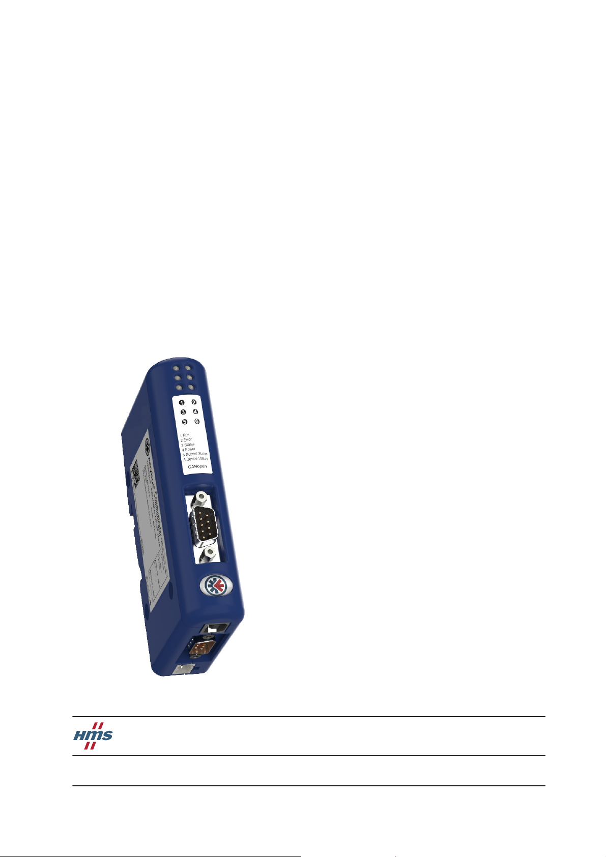
Anybus Communicator CAN to CANopen
Doc.Rev. 1.00
Important User Information
This document is intended to provide a good understanding of the functionality offered by the Anybus Communi-
cator CAN - CANopen.
The reader of this document is expected to be familiar with high level software design, and communication
systems in general. The use of advanced CANopen specific functionality may require in-depth knowledge of
CANopen networking internals and/or information from the official CANopen specifications. In such cases, the
people responsible for the implementation of this product should either obtain the CANopen specification to gain
sufficient knowledge or limit their implementation in such a way that this is not necessary.
Liability
Every care has been taken in the preparation of this manual. Please inform HMS Industrial Networks AB of any
inaccuracies or omissions. The data and illustrations found in this document are not binding. We, HMS Industrial
Networks AB, reserve the right to modify our products in line with our policy of continuous product development.
The information in this document is subject to change without notice and should not be considered as a commit-
ment by HMS Industrial Networks AB. HMS Industrial Networks AB assumes no responsibility for any errors that
may appear in this document.
There are many applications of this product. Those responsible for the use of this device must ensure that all the
necessary steps have been taken to verify that the applications meet all performance and safety requirements in-
cluding any applicable laws, regulations, codes, and standards.
HMS Industrial Networks AB will under no circumstances assume liability or responsibility for any problems that
may arise as a result from the use of undocumented features, timing, or functional side effects found outside the
documented scope of this product. The effects caused by any direct or indirect use of such aspects of the product
are undefined, and may include e.g. compatibility issues and stability issues.
The examples and illustrations in this document are included solely for illustrative purposes. Because of the many
variables and requirements associated with any particular implementation, HMS Industrial Networks AB cannot
assume responsibility for actual use based on these examples and illustrations.
Intellectual Property Rights
HMS Industrial Networks AB has intellectual property rights relating to technology embodied in the product de-
scribed in this document. These intellectual property rights may include patents and pending patent applications
in the US and other countries.
The “Silk” icon set, used in the Anybus Configuration Manager tool, is created by Mark James, Birmingham, Eng-
land. The complete icon set is found at http://famfamfam.com/lab/icons/silk/. The icon set is licensed under the
Creative Commons Attribution 2.5 License (http://creativecommons.org/licenses/by/2.5).
Trademark Acknowledgements
Anybus ® is a registered trademark of HMS Industrial Networks AB. All other trademarks are the property of their
respective holders.
Warning: This is a class A product. in a domestic environment this product may cause radio interference in
which case the user may be required to take adequate measures.
ESD Note: This product contains ESD (Electrostatic Discharge) sensitive parts that may be damaged if ESD
control procedures are not followed. Static control precautions are required when handling the prod-
uct. Failure to observe this may cause damage to the product.
Anybus Communicator CAN - CANopen User Manual
Rev 1.00
Copyright© HMS Industrial Networks AB
June 2011 Doc Id SCM-1200-121