USER MANUAL
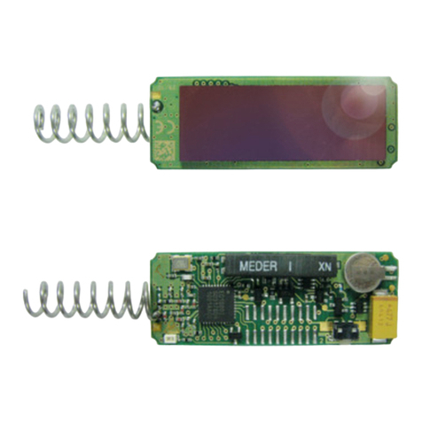
PTM 535 / PTM 535U / PTM 535J –ENOCEAN TRANSMITTER MODULE
© 2019 EnOcean | www.enocean.com F-710-017, V1.0 PTM 535 / 535J User Manual | v1.5 | September 2020 | Page 3/36
TABLE OF CONTENT
1General description........................................................................................5
1.1 Product description ........................................................................................5
1.2 Product variants ............................................................................................5
1.3 Technical data...............................................................................................6
1.4 Maximum ratings for input signals ...................................................................6
1.5 Physical dimensions .......................................................................................6
1.6 Device drawing ............................................................................................. 7
1.7 Environmental conditions ...............................................................................8
1.8 Ordering information .....................................................................................8
2Functional description ....................................................................................9
2.1 Functional Principle........................................................................................9
2.2 Block diagram ...............................................................................................9
2.3 Interface pin layout ..................................................................................... 10
2.4 Interface pin functionality............................................................................. 11
3Radio telegram format ................................................................................. 12
3.1 Standard mode ........................................................................................... 12
3.2 Enhanced security mode .............................................................................. 14
3.3 Switching between operation modes .............................................................. 15
3.4 Transmission timing..................................................................................... 15
4PTM 535 configuration ................................................................................. 16
4.1 PTM 535 configuration parameters ................................................................ 16
4.2 PTM 535 configuration interface .................................................................... 17
4.3 PTM 535 test point location........................................................................... 17
4.4 Connection between Segger J-Link and PTM 535 ............................................. 18
4.4.1 Segger power supply (6-Pin interface).................................................... 18
4.4.2 External power supply (4 pin configuration interface) ............................... 19
4.5 Required tools............................................................................................. 20
4.6 Configuration setup ..................................................................................... 21
4.7 User Interface............................................................................................. 21
4.8 Execution sequence ..................................................................................... 22
5Application information ................................................................................ 23
5.1 Connection to ECO 200 energy harvester ....................................................... 23
5.2 How to populate a teach-in button (for enhanced security mode) ...................... 23
5.3 Antenna specification ................................................................................... 24
5.4 Layout recommendations ............................................................................. 25
5.5 Transmission range ..................................................................................... 26
6Regulatory information................................................................................. 27
6.1 RED (European Union) ................................................................................. 27
6.2 FCC (United States) ..................................................................................... 28
6.2.1 FCC grant of equipment authorization .................................................... 28
6.2.2 FCC regulatory statement ..................................................................... 29
6.3 ISED (Canada)............................................................................................ 30
6.3.1 ISED technical acceptance certificate...................................................... 30
6.3.2 ISED regulatory statement.................................................................... 32
6.3.2.1 English version ................................................................................. 32
6.3.2.2 French version.................................................................................. 33
6.4 ARIB (Japan) .............................................................................................. 34


