-BSK5217M**1K 8/9-
Parameters Factory
setting
Variable Description
【01.】M18: 5
M30: 6
M18: 6
M30: 7
0-100%
Threshold
【02.】
5
0-100%
Hysteresis
【03.】80
0-100%
Alarm Hi
【04.】0-100%
Alarm Lo
【05.】
50
3-255
【06.】
0
Normally open
Normally closed
0
NO/NC
【07.】
0
OFF
ON
0
Alarm feature
【10.】
0
Delay timer disabled
ON delay timer
Delay timer
ON/OFF
【11.】0-255 0
Delay
1
1
0
1
OFF delay timer
ON/OFF delay timer
2
3
■General Specications
■Transmission Specications
■Individual Specications
<Ambient atmosphere>
Current consumption
Occupied number of points
Weight (Main unit, cable)
Detection target*3
Depends on the parameter setting
10ms max.
Detection distance
(at the ambient temperature of 23°C)
Hysteresis
A grounded metal piece of 50×50×1mm
Standard detection substance
Response time*4
The detection distance at 23°C
Inuence of temperature
Inuence of voltage
M18: Approx. 38g M30: Approx. 64g
Weight (Nut) M18: Approx. 2g M30: Approx. 3g
M18: 8mm(max.)M30: 15mm(max.)
Stable detection distance M18: 0 – 6.4mm M30: 0 – 12mm
M18: Within ±20% M30: Within ±20%
IP67
Protection class
Supplied by the AnyWireASLINK transmission signal (DP, DN)
Conductors/dielectrics
M18: 7.5mA M30: 7.6mA
1 input point
Should any of the following apply, take the following actions.
Symptom
Remedy
LINK IN ALM Cause Remedy
○○ ○
Unlit Unlit Unlit
●
Lit
○
Unlit
○
Unlit
◎
Flashing
○
Unlit
◎
Flashing
--◎
Flashing
◎-●
Flashing Lit
◎ -
Flashing
Display Cause
Remedy
【E-0303】
l
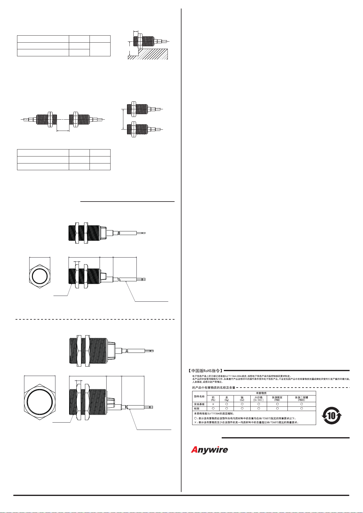
φ
d
m
n
l d m n
BS-K5217-M18-1K 15 40 10 60
(Unit: mm)
BS-K5217-M30-1K 10 60 20 60
*5Metal body
[Troubleshooting]
If the following statuses of the LEDs are indicated on the
ASLINKSENSOR, take the following actions.
If the following error is indicated on the Address Writer, take the
following action.
(alternates
with a 0.5 sec
interval)
(alternates
with a 0.5 sec
interval)
◎
Flashing
(alternates
with a 0.1 sec
interval)
(Lit for 0.2
sec, unlit for
1.0 sec)
-
The ASLINKSENSOR
is not connected to
the AnyWireASLINK
system.
-
The AnyWireASLINK
system is not turned
on.
- Check if there is a disconnection
between the ASLINKSENSOR and
AnyWireASLINK system and, if there
was a disconnection, restore the
connection.
- Check the power supply of
AnyWireASLINK system and turn ON
the power.
- Connected directly to
the 24-0V power supply.
- Reconnect the power to the
AnyWireASLINK system.
- The address of
ASLINKSENSOR
remains as “255”
(factory setting).
- The address of
ASLINKSENSOR is
duplicated.
- The transmission
signal level is
detected low.
- Assign an address other than 255.
- Look for a unit that has the same error
and assign an address different from
the address of that unit.
- Reduce the number of units connected
to the same AnyWireASLINK system.
- Reduce the length of transmission line
between ASLINKSENSOR and the
master unit.
- Check the condition of
ASLINKSENSOR, adjust its position
and clean the detection face.
- The sensing level is
low.
- Perform the teaching operation again.
- Teaching has not
been performed
properly.
The parameter setting is
incorrect.
Check the parameters and correct
them accordingly.
Detection cannot
be made
- Is the metal piece to be detected in an appropriate position?
→
Adjust the position of metal piece so that it will be in an
appropriate range from the detection face of
ASLINKSENSOR.
- Is the wiring correct?
→Ensure that the ASLINKSENSOR transmission line is
connected to the AnyWireASLINK system transmission line
(DP, DN) properly.
- Is there a power supply with a capacity appropriate for the
AnyWireASLINK master and slave units and turned ON?
→
Check the power supply.
- Has teaching been performed?
→
Perform teaching using the workpiece to be detected in the
operation.
- Is the sensor used in the specied detection range?
→
Use it within its rating.
Setting cannot be
made with the
Address Writer
- Is the wiring correct?
→
Check the connection of ASLINKSENSOR transmission
line once more.
- Is the power supplied to the AnyWireASLINK system?
→
Check the power supply.
- Are the parameters set correctly?
→
Check the parameters and correct them accordingly.
[Parameter and Setting Items]
The threshold of sensing level to
determine if a detection is made
The change in the sensing level required
for the detection status to change from
ON to OFF
The upper limit for alarm determination
The lower limit for alarm determination
The monitoring time for alarm
determination (1=100ms)
The delay for the delay timers
(1=100ms)
[Specifications]
Ambient temperature/humidity use -10 – 60°C, 10 – 90%RH No condensation
-25 – 75°C, 10 – 90%RH No condensation
No corrosive gas
Ambient temperature/humidity storage
Atmosphere use
Altitude use*1
Pollution level*2
0 – 2000m
2 or less
*1 Do not use or store AnyWireASLINK devices in an environment where the pressure exceeds
the atmospheric pressure at an altitude of 0 meters. Doing so may result in malfunction.
*2“Pollution level” is an index that indicates the degree of occurrence of conductive substances
in the environment where the device is used.
Pollution level 2 means the occurrence of only pollution by non-conductive substances.
In such an environment, however, electrical conduction could occur due to accidental condensation.
*3 The detection distance varies depending on the material.
*4The time from detecting the ON or OFF condition until the transmission signal is sent.
This time plus two transmission cycles will be the transmission delay.
*5 If the metal body is not grounded, the operation may be unstable. Always ground it.
Within ±1% of detection distance in the range of 27.6 to 21.6V
power supply voltage for the AnyWireASLINK master unit.
Avoid using the device with splashes of water, oil or chemicals on it or in an
atmosphere causing condensation as those fluids may be recognized as
detection targets and leading to erroneous detections.
The device is especially sensitive to dielectrics and can be influenced by
even a tiny drop of water.
<Influence of surrounding metals>
If the device is to be mounted in a metal body, ensure the distances listed in
the table below.
Also ensure the distances shown on this table for installations in materials
other than metals (such as resin) could have an influence on the detection.
Alarm
monitoring time
Service power supply
voltage
24V DC +15% to -10% (21.6 to 27.6V DC) with a ripple of
0.5Vp-p or less
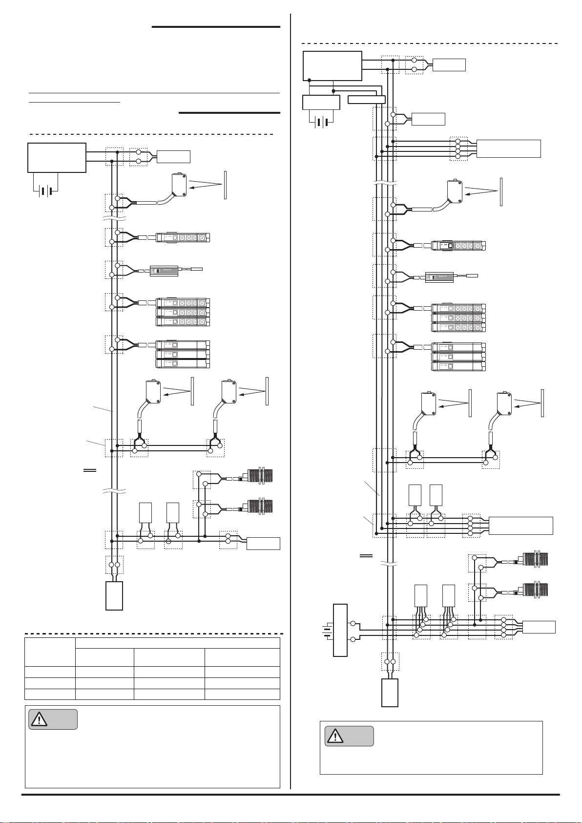
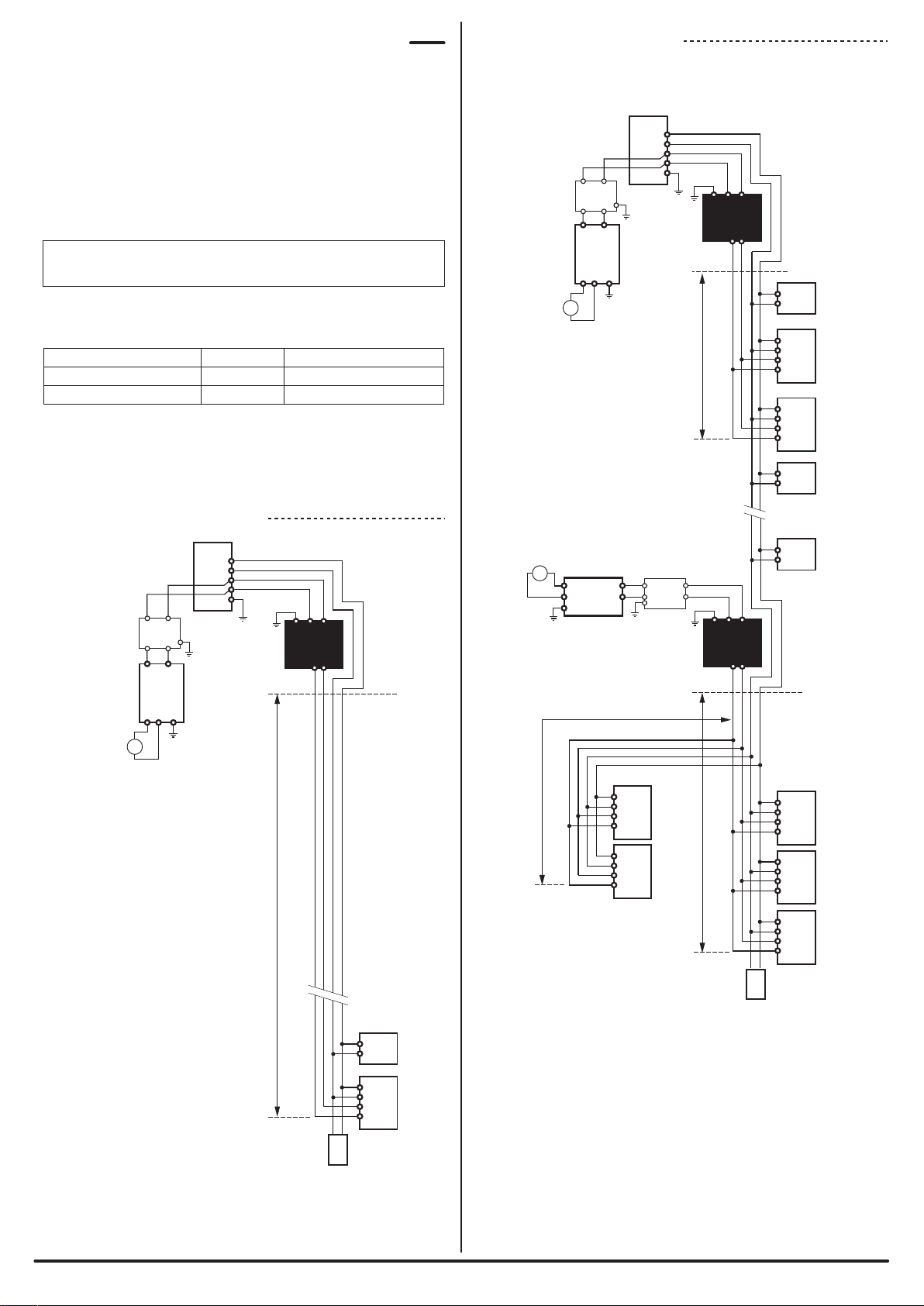
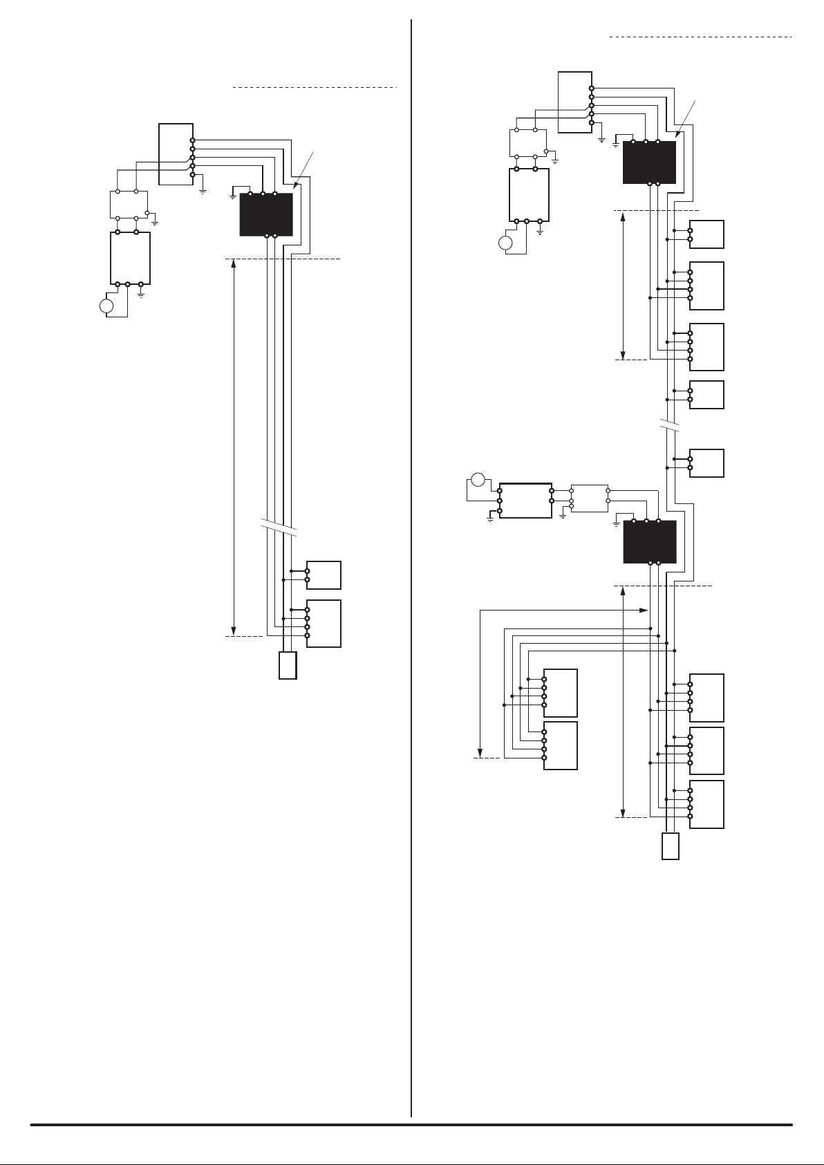
Bus type (Multi-drop method, T-branch method,
Tree branch method)
DC power supply superimposed total frame/cyclic method
Transmission method
Frame/bit synchronization method
Synchronization method
Dedicated protocol
512 max. (IN: 256, OUT: 256)
Up to 128 units
Transmission procedure
Connection mode
RAS features
Number of connection
points
Number of units that can
be connected
Detection of transmission line disconnection, detection of
transmission line short circuit, detection of transmission power
drop, detection of duplicated/unregistered ID