Anywire ASLINKSENSOR BS-K4117-M 1K Series User manual

AnyWireASLINK System Products Guide
ASLINKSENSOR [ASLINK Sensor]
BS-K4117-M□□-1K
[Notes on Safety]
A WARNING indicates a potentially hazardous situation which, if not
handled correctly, could result in death or serious injury.
A CAUTION indicates a potentially hazardous situation which, if not
handled correctly, may result in personal injury or property damage.
[Warranty]
CAUTION
!
WARNING
!
CAUTION
!
WARNING
Precautions that must be observed in order to use this system safely are
indicated as shown below. You must observe these precautions.
!
■Warranty period
The warranty on the delivered Product shall continue to be effective for one (1)
year after the delivery thereof to a location as designated by the original owner.
■Scope of warranty
Should a defect occur in any part of the Product during the foregoing warranty
period when it is used normally in accordance with the specications described
in this User's Manual, the Company shall replace or repair the defect free of
charge, except when it arises as a result of:
[1] Misuse or abuse of the Product by the owner;
[2] Fault caused by cause other than the delivered Product;
[3] Unauthorized modication or repair of the Product by any party other than
the Company;
[4] Any unusual force of nature, disaster, or other cause beyond the Company's
control.
The term "warranty," as used herein, refers to the warranty applicable to the
delivered product alone. The Company shall not be liable for any damages
consequential or incidental to a malfunction of the delivered product.
■Repair at cost
After the expiration of the warranty period, any troubleshooting or repairs shall
be done at the expense of the owner.
Even during the warranty term, any repairs and troubleshooting for defects
arising from causes outside the scope of the warranty as specied above shall
be done at the owner's expense.
○System Safety
This system is intended for general industrial applications. It does not
have functions for supporting applications requiring higher levels of safety
such as safety-related devices or accident prevention systems.
○Always turn off the system power before attempting to mount or replace.
○Prolonged continuous ow of a rated load current or higher or a transit
current due to load short-circuit or similar problem, in the hybrid unit
including the output unit and the output circuit may result in smoke
generation or re. An external safety device such as a fuse must be
installed.
○System power supply
Use a stabilized 24V DC power supply. Use of a non-stabilized power
supply may cause problems with the system.
○Separately route high-voltage and power cables
Although the AnyWireASLINK has a high noise margin, lay the
transmission lines and I/O cables so as to keep them away from
high-voltage and power cables.
○Connectors and terminals
・Pay careful attention to the length and installation of cable wiring to
ensure that connectors and cables are neither stressed nor
disconnected even if they are stressed.
・Make sure to prevent any metal objects from getting inside the
connectors or the terminal blocks.
・Short-circuits caused by metal objects or mis-wiring are likely to
damage the device.
○Do not impose any external loads on the units.
Doing so may cause a failure.
○Do not disconnect or reconnect between the transmission line and slave
units when a transmission line is operating.
A malfunction may occur.
○Use the AnyWireASLINK within the range of the specications and
conditions shown below.
[Type]
ASLINKSENSOR two-wire (non-isolated) terminal
Electromagnetic induction type
Sensitivity adjustment value (Threshold)
Hysteresis
Alarm judgment value
Alarm judgment time
Normally open/Normally close
Delay timer
Slave unit voltage drop
Sensing level drop
Teaching abnormality
Detection method
Model
Functions
READER/WRITER
ARW-04 Ver.04-1.01LotNo.***
MADE IN JAPAN
"Ver.*.**" is
written on
this label.
The version is
displayed when
the power is
turned on.
Front Rear
ARW-04
-BSK4117M**1K 1/9-
Transmission cable
(Oil-resistant, ex-resistant type) DP (red)
DN (black)
LINK display
IN display
ALM display
Setting port
Detection surface
Full thread
Toothed washer
Example for BS-K4117-M18-1K
[Function]
[Included items]
[Name of each part]
BS-K4117-M12-1K M12, black nickel plating
BS-K4117-M18-1K M18, black nickel plating
BS-K4117-M30-1K M30, black nickel plating
AnyWireASLINK proximity sensor: Amplier-embodied type,
all metal detection type
This product...1
Nut...2
Toothed washer...1
BS-K4117-M12-1K
BS-K4117-M30-1K
BS-K4117-M18-1K
* If mounting clamps are required, please purchase them separately.
* Setting of addresses in this product requires the "address writer ARW-04
(Ver.04-1.01 or higher) or ARW-03 (Ver.2.10 or higher)." Prepare that as well.

-BSK4117M**1K 2/9-
■Example of mixture of two-wire (non-isolated)
and four-wire (isolated) terminals
ALM
LINK
IN
4P link connector is
convenient for
branching.
The branching has
no limitation.
Dedicated at cable
1.25mm2(four-wire)
Black: DN
Red: DP
Black:
DN
Red: DP
AnyWireASLINK
Master
24V DC* Black: DN
Red: DP
Black: DN
Red: DP
Black: DN
Red: DP
Red: DP Black: DN
Black: DN
Red: DP
AnyWireASLINK terminator
One terminator should be connected to the DP, DN terminal
farthest from the AnyWireASLINK master.
Connect it correctly so as not to set the wrong polarity.
Black: DN Red: DP
BT0
Red: DP Black: DN
ALM
LINK
IN
ALM
LINK
IN
ALM
LINK
IN
ALM
LINK
IN
ALM
LINK
IN
ALM
LINK
IN
Black: DN
Red: DP
Black: DN
Red: DP
Two-point
Two-point
Two-point
Two-point
Two-point
Two-point
Two-point
Eight-point
Eight-point
24V DC*
ASLINKAMP
Solitary use
ASLINKAMP
Expansion use
ASLINKAMP
Expansion use
ALM
LINK
IN
■Connection example using a two-wire (non-isolated) terminal
The branching has
no limitation.
Black: DN
Red: DP
Black:
DN
Red: DP
AnyWireASLINK
Master
24V DC* Black: DN
Red: DP
Black: DN
Red: DP
Black: DN
Red: DP
Black: DN
Red: DP
AnyWireASLINK terminator
One terminator should be connected to
the DP, DN terminal farthest from the AnyWireASLINK master.
Connect it correctly so as not to set the wrong polarity.
Black: DN Red: DP
BT0
Red: DP Black: DN
ALM
LINK
IN
ALM
LINK
IN
ALM
LINK
IN
ALM
LINK
IN
ALM
LINK
IN
ALM
LINK
IN
Black: DN
Red: DP
Black: DN
Red: DP
Two-point
Two-point
Two-point
Two-point
ASLINKAMP
Solitary use
ASLINKAMP
Expansion use
ASLINKAMP
Expansion use
Recurrent reflection type
Recurrent reflection type Recurrent reflection type
Black: DN
Red: DP
Recurrent reflection type
Recurrent reflection type Recurrent reflection type
Reection
panel
(Sold
separately)
Reection
panel
(Sold
separately)
General-purpose power supply lter
ASLINK lter
[Connection Example]
[How to connect AnyWireASLINK]
You can select use of either a two-wire or four-wire terminal for the AnyWireASLINK according
to the load current.
This Products Guide describes a two-wire (non-isolated) terminal.
If the load current is small, using a two-wire (non-isolated) terminal allows for achieving
simplied wiring without a local power supply.
If you are prioritizing the sites of concentrated loads or the number of units connected,
hybridization with a four-wire (isolated) terminal, which supports local power supply, is also
possible.
Make sure to use a four-wire (isolated) terminal in the case of input and load driving using an
external power supply.
In the case of hybridization, refer to the Four-Wire (Isolated) Terminal Products Guide
separately.
■Relationship between the size and length of the transmission line
and the supply current (Table 1)
2P link connector is
convenient for branching.
Dedicated at cable
1.25mm2(two-wire)
* Make sure to use a
24V DC stabilized
power supply for the
power supply to be
connected.
* When complying with the
UL Standard, make sure
to use a 24V DC stabilized
power supply of "NEC
Class 2 Output."
The sum of the
portions of DP, DN is
the total line length.
The sum of the
portions of DP, DN is
the total line length.
CAUTION
!- Refer to Table 1 so that the size and length of the
transmission line and the allowable supply current lie
within an appropriate range.
- Connect the same symbols (DP, DN) correctly between the AnyWireASLINK
master and each device.
- The branching length and branch number have no limitations.
- Include the length of the cable provided with the terminal in the "total line
length."
- Connect the terminator "BT0 (polar)" to the terminal on the transmission line
farthest from the AnyWireASLINK master.
CAUTION
!
Make sure to use a four-wire (isolated) terminal if connecting
to a load (e.g. input/output port) controlled by a different
power supply than that used in the AnyWireASLINK.
Otherwise, a malfunction may occur.
Supply current on the transmission line (DP, DN)
Total length
50m or less
Size of
the transmission
line (DP, DN)
1.25mm2
0.75mm2
MAX 2A
MAX 1.2A
MAX 1A
MAX 0.6A
MAX 0.5A
MAX 0.3A
0.5mm2MAX 0.8A MAX 0.4A MAX 0.2A
Total length: Over 50m,
no longer than 100m
Total length: Over 100m,
no longer than 200m

-BSK4117M**1K 3/9-
■AnyWire Type: ANF-01 Connection example
①Power supply to the entire system
②Local power supply/branching
DP
DN
24V
0V
POWER IN
SLAVE
POWER IN
SLAVE
LG
24V0V
L N FG
~
DP
DN
DP
DN
24V
0V
DP
DN
BT0
ANF-01
24V DC
stabilized
power supply
Two-wire
terminal
Four-wire
terminal
24V0V
24V0V
PE
AnyWireASLINK master
[Notes on Combined Use with Four-Wire (Isolated) Terminals]
DP
DN
24V
0V
LG
24V0V
L N FG
~
DP
DN
24V
0V
DP
DN
DP
DN
24V
0V
DP
DN
BT0
ANF-01
24V DC
stabilized
power
supply
Two-wire
terminal
DP
DN
Two-wire
terminal
DP
DN
Two-wire
terminal
Four-wire
terminal
DP
DN
24V
0V
Four-wire
terminal
Four-wire
terminal
DP
DN
24V
0V
Four-wire
terminal
DP
DN
24V
0V
Four-wire
terminal
24V0V
24V0V
PE
AnyWireASLINK master
24V
0V
L
N
FG
~
24V DC
stabilized
power supply
ANF-01
24V0V
24V0V
PE
DP
DN
24V
0V
Four-wire
terminal
DP
DN
24V
0V
Four-wire
terminal
A
B
General-purpose
power supply filter
(Use if necessary)
ASLINK filter ANF-01 MAX 5A/24V DC
Filter of COSEL Co., Ltd. EAC-06-472 MAX 6A/24V DC
Model Type
Allowable power current
■Filter allowable power current
Insert the "ASLINK filter [Type ANF-01]" regardless of
installation method and distance when complying with CE Standard.
General-purpose
power supply filter
(Use if necessary)
General-purpose
power supply filter
(Use if necessary)
POWER IN
SLAVE
(The gure is an explanatory schematic.
Adjust the actual terminal layout to meet each device.)
If any of the side-by-side lines of DP, DN, 24V, or 0V exceeds the total length of
50m in a power supply system to be supplied, serially connect the "ASLINK filter
[Type ANF-01]" or a "filter of COSEL Co., Ltd. [Type EAC-06-472]" to 24V and 0V
in the starting position of the side-by-side lines.
This will improve noise resistance, reduce the impact of crosstalk by transmission
signals, and stabilize the signals.
Insert a filter whether using a master power supply for the entire system or using a
local power supply.
If any of the side-by-side lines
of DP, DN, 24V, or 0V exceeds
the total length of 50m
If (A+B) of the side-by-side
lines of DP, DN, 24V, or 0V
exceeds the total length of 50m
If any of the side-by-side lines
of DP, DN, 24V, or 0V exceeds
the total length of 50m

-BSK4117M**1K 4/9-
■COSEL Co., Ltd. Type: EAC-06-472 Connection example
①Power supply to the entire system
②Local power supply/branching
DP
DN
24V
0V
LOAD
LINE
LG
24V0V
L N FG
~
DP
DN
DP
DN
24V
0V
DP
DN
BT0
EAC-06-472
24V DC
stabilized
power supply
Two-wire
terminal
Four-wire
terminal
24V0V
24V0V
PE
AnyWireASLINK master
If (A+B) of the side-by-side lines
of DP, DN, 24V, or 0V exceeds
the total length of 50m
DP
DN
24V
0V
LG
24V0V
L N FG
~
DP
DN
24V
0V
DP
DN
DP
DN
24V
0V
DP
DN
BT0
24V DC
stabilized
power supply
If any of the side-by-side lines
of DP, DN, 24V, or 0V exceeds
the total length of 50m
Two-wire
terminal
DP
DN
Two-wire
terminal
DP
DN
Two-wire
terminal
Four-wire
terminal
DP
DN
24V
0V
Four-wire
terminal
Four-wire
terminal
DP
DN
24V
0V
Four-wire
terminal
DP
DN
24V
0V
Four-wire
terminal
24V0V
24V0V
PE
AnyWireASLINK master
24V
0V
L
N
FG
~
24V DC
stabilized
power supply
24V0V
24V0V
PE
DP
DN
24V
0V
Four-wire
terminal
DP
DN
24V
0V
Four-wire
terminal
A
B
General-purpose
power supply filter
(Use if necessary)
General-purpose
power supply filter
(Use if necessary)
General-purpose
power supply filter
(Use if necessary)
LOAD
LINE
EAC-06-472
LOAD
LINE
EAC-06-472
(The gure is an explanatory schematic.
Adjust the actual terminal layout to meet each device.)
When using this lter,
please be careful of the
positions of LOAD and
LINE.
When using this lter,
please be careful of the
positions of LOAD and
LINE.
If any of the side-by-side lines
of DP, DN, 24V, or 0V exceeds
the total length of 50m

-BSK4117M**1K 5/9-
[How to connect] [Installation Examples]
Use the toothed washer when affixing.
Tightening torque: 5.9N・m
φ12.5
- Installation hole
radius
Setting port
Use the toothed washer when affixing.
Tightening torque: 15N・m
φ18.5
- Installation hole
radius
Setting port
Use the toothed washer when affixing.
Tightening torque: 59N・m
φ30.5
- Installation hole
radius
Setting port
<BS-K4117-M12-1K>
<BS-K4117-M18-1K>
<BS-K4117-M30-1K>
Red: DP (+)
Black: DN (-)
Connect to the AnyWireASLINK transmission line (DP, DN).
DP and DN have polarity, so be sure to connect correctly.
■Example of mounting an LP connector to the end of the transmission line
Applicable LP connector: LP2-PWH-10P (2P), LP4-WW-10P (4P)
Transmission line
UL style 2103
Two cores of No.24 AWG (black) φ4.1
Core line finished
outside diameter
φ1.5
2 1
AB
CCover
Hole to pass clamp through
Clamp
① ②
⑤ ⑥
③ ④
Dedicated tool: LP-TOOL
Example for BS-K4117M-M18-1K
* The following explanatory gure is an example for the LP2-PWH-10P.
Place the lines in the groove so that the black line
(DN) is positioned nearer the hinge side (pin 1) of
the cover, and fold part A onto the part B side, and
then hitch the hook C to x the cover.
Insert the body clamp into the hole
of the cover and crimp them with a
dedicated tool.
For the LP4-WW-10P, perform crimping with pin 1 for DN, pin 2 for DP, and
pins 3 and 4 empty.
After crimping, check
that the hooks ③to ⑥
are securely engaged.
With cover mounted
Check that the hooks ①
and ②are engaged.
[Installation Location]
[Precautions for Use]
If you expect you will change the settings, install the unit so that the setting
port is visible.
CAUTION
!
When affixing this product, provide enough slack so that cables and connection
connectors are not stressed.
Do not over-tighten screws. Doing so may cause a failure.
- Location where this product is not directly subject to vibration or shock
- Location without condensation
- Location where the atmosphere is free of corrosive gas, ammable gas, and
sulfur
- Location far from high-voltage or high-current cables
- Location far from cables and controllers that generate servo, inverter, or other
high-frequency noise
- Location away from direct sunlight
- This unit is to be used connected to an AnyWireASLINK transmission line.
It will not operate if it is directly connected to the sequence I/O card or the like.
- Use with an appropriate voltage range.
- Include the transmission line provided with this product in the total line length.

-BSK4117M**1K 6/9-
Parameter setting
■Setting of threshold
■Setting of hysteresis
Default: BS-K4117-M12-1K : 18
BS-K4117-M18-1K : 24
BS-K4117-M30-1K : 26
- Address writer (ARW-04, ARW-03): Parameter 01
Default: 5
- Address writer (ARW-04, ARW-03): Parameter 02
Variable
0 - 100
Unit
%
Variable
0 - 100
Unit
%
Set the threshold of the sensing level to judge presence/absence of
detection. * Difference in the detection state stored in teaching is 100%.
Set change amount of sensing required to turn detection state ON to
OFF after turning the detection state OFF to ON.
Fig. 2
[Various settings]
■Item
Black: DN
Red: DP
Transmission
signal
AnyWireASLINK
Master
24V DC*
Setting port
Address number setting Parameter settingTeaching
■Common procedure for address writer operation
Be sure to connect to the AnyWireASLINK master unit to use.
An address writer ARW-04 (Ver.04-1.01 or higher) or ARW-03
(Ver.2.10 or higher) is required for operation.
For details about the operation method, refer to the address
writer's Products Guide.
1. Connect the AnyWireASLINK slave to the AnyWireASLINK master unit.
Set with the address writer while supplying transmission signals (DP, DN).
2. Setting is required for all AnyWireASLINK devices.
Direct the address writer toward the setting port (Fig. 2) of this product.
(Bring the emitter as close as possible to the setting port.)
* When setting is changed in the [WRITE] mode, the setting is reected after
the system is re-started up.
When setting is changed in the [DIRECT WRITE] mode, the setting is reected
at the time when the writing is completed.
* If this unit is included in a parallel arrangement, use the remote head
(ARW-RH) together, and ensure that writing is not performed to terminals not
intended.
* Make sure to use a 24V DC stabilized
power supply for the power supply to be
connected.
Teaching
Address number setting
The address number is used to set which number of the transmission
frame to start with for the terminal to occupy.
Set the address number in a range from "0" to "254."
Store the status when a work is present and when a work is absent in
the ASLINKSENSOR.
The default address-number setting of the terminal is "255," which means
no setting.
If the address number setting is "255," the terminal cannot perform
input/output operations.
Make sure to use the terminal after setting the address number within the
range of "0 to 254."
CAUTION
!
[SET ON setting]
[SET OFF setting]
Set with detected metal present.
Set with detected metal absent.
Black: DN
Red: DP
AnyWireASLINK
Master
Detected
metal
Black: DN
Red: DP
AnyWireASLINK
Master
Keep half or more
of the maximum
detection distance
- Carry out setting with the work actually used.
Maintain 50% or more of the maximum detection distance
while performing settings.
- When the difference between the with/without a workpiece
statuses is insufficient, ALM flashes to let you know the
status. Perform setting again.

-BSK4117M**1K 7/9-
LINK (Green)
IN (Orange)
ALM (Red)
LINK
(Green)
LINK
ALM
IN
(Orange)
Name Indication status
ALM
(Red)
Details
Transmission signal is appropriately supplied
Sensing level drop*
Slave unit voltage drop
Transmission signal error
No transmission signal
Normal
When the master unit found that
the ID (address) of this unit is duplicate
or is not set.
ON
OFF
Flashing
On
Flashing
(On for 0.2 seconds,
off for 1.0 second)
(0.1 seconds alternately)
Alternate flashing
On
Off
Off
On
Off
Teaching abnormality
Flashing
LINK
ALM
* Only when alarm diagnosis function is enabled
■Setting for operation mode change
■Setting for delay timer value
■Setting for delay timer ON/OFF
If you set the delay timer in parameter 10, you can set the delay time.
Set if there is an alarm diagnosis function.
Variable Details
0 Simple mode Alarm diagnosis function disabled
Alarm diagnosis function enabled1 Normal mode
- Address writer (ARW-04, ARW-03): Parameter 07
Default: 0
Variable Details
0 No delay timer Delay timer disabled
1
2
3
ON delay timer
ON/OFF delay timer ON/OFF delay timer enabled
OFF delay timer
ON delay timer enabled
OFF delay timer enabled
- Address writer (ARW-04, ARW-03): Parameter 10
Default: 0
Set the ON delay timer/OFF delay timer.
0 - 255 Default: 0
- Address writer (ARW-04, ARW-03): Parameter 11
■Normally open/Normally close setting
Variable Details
0 Normally open ON with work present
Set the normally open/normally close.
1 Normally close ON with work absent
■Alarm value Hi setting
■Alarm value monitor time setting
■Alarm value Lo setting
Set an upper limit for the alarm judgment value.
Set a lower limit for the alarm judgment value.
Set a monitor time for the alarm judgment value.
* Set the alarm values so that Hi is greater than Lo.
Default: 80
- Address writer (ARW-04, ARW-03): Parameter 03
Default: 50
- Address writer (ARW-04, ARW-03): Parameter 04
- Address writer (ARW-04, ARW-03): Parameter 05
- Address writer (ARW-04, ARW-03): Parameter 06
Variable
0 - 100
Unit
%
Variable
0 - 100
Unit
%
Variable
3 - 255
Unit
100ms
Default: 0
Variable Unit
10ms
Default: BS-K4117-M12-1K : 19
BS-K4117-M18-1K : 25
BS-K4117-M30-1K : 27
CAUTION
!Parameters [08, 09, 12 to 19] are items related to
internal settings. Do not perform settings.
[Monitor display]
Displays the operation status of this product using the LEDs.
Normal state: LINK flashing, ALM off, IN ON on/OFF off

-BSK4117M**1K 8/9-
[Specications]
-10 - 60°C, 10 - 90%RH (No condensation)
Ambient temperature/humidity for use
-25 - 75°C, 10 - 90%RH (No condensation)
Ambient temperature/humidity for storage
No corrosive gas
■General Specications
Atmosphere for use
0 to 2000m
Altitude of use *1
2 or less
Pollution level *2
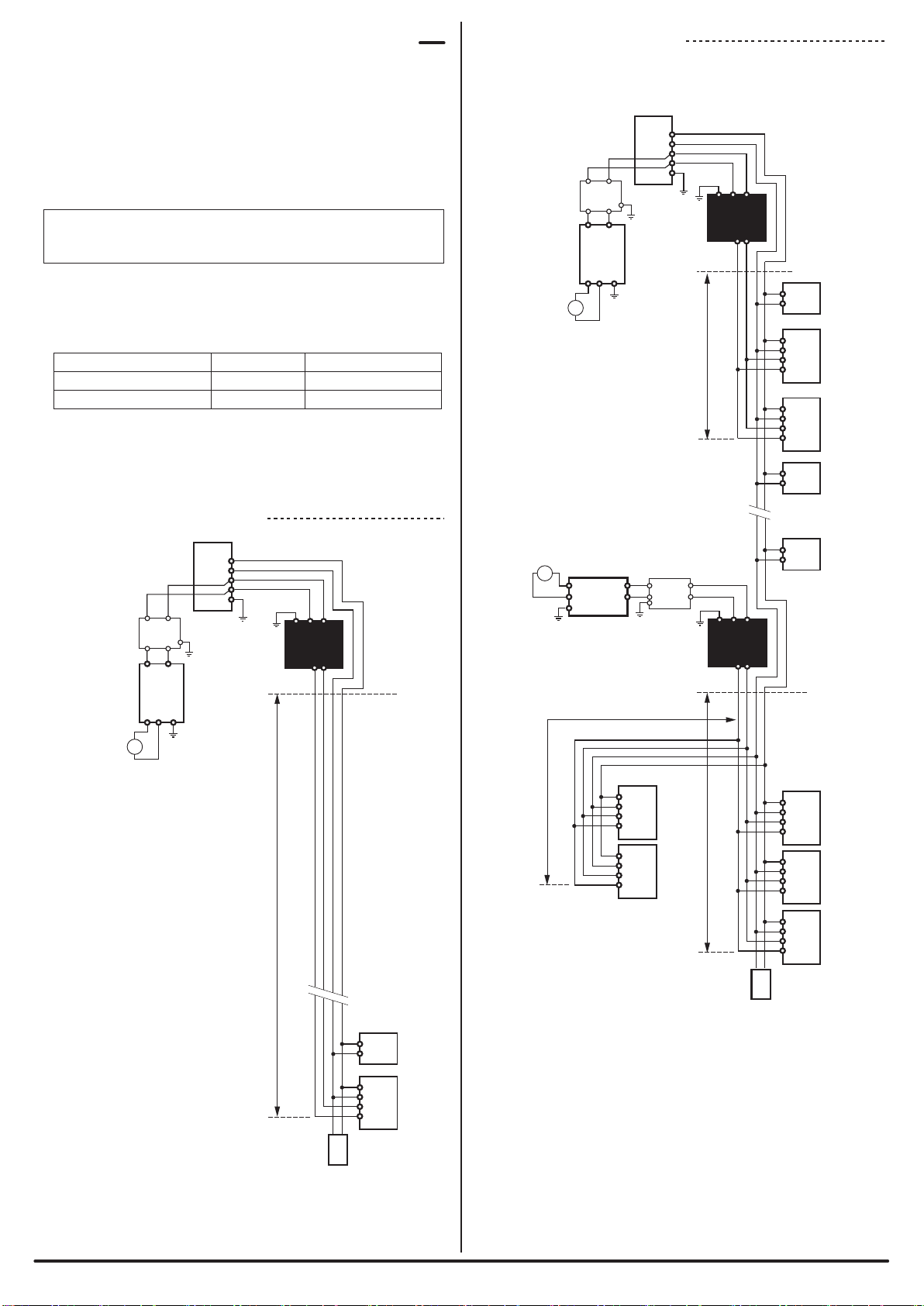
■Transmission specications
Frame/bit synchronization method
Synchronization method
DC power supply superimposed total frame/cyclic method
Transmission method
Voltage 24V DC +15% to -10% (21.6 to 27.6V DC
Ripple of 0.5Vp-p max.
Power supply voltage
for use
Dedicated protocol
Transmission procedure
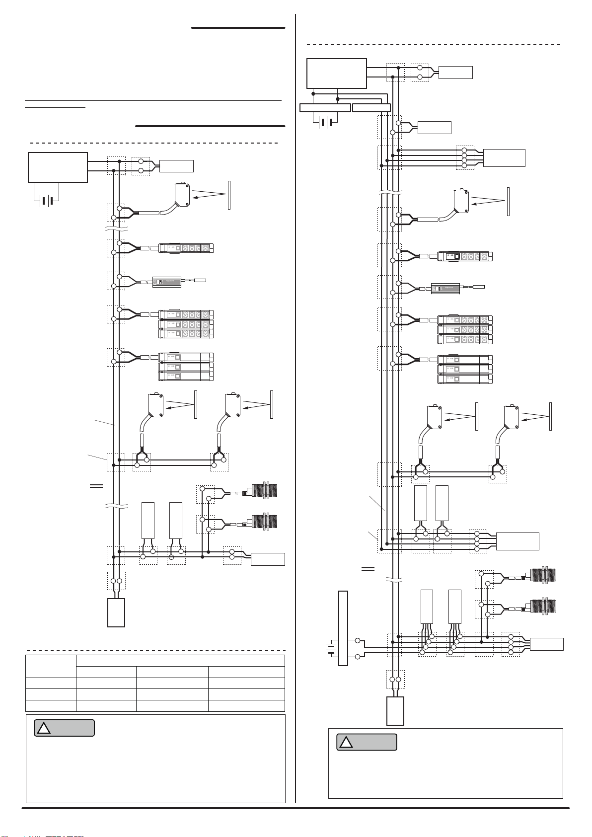
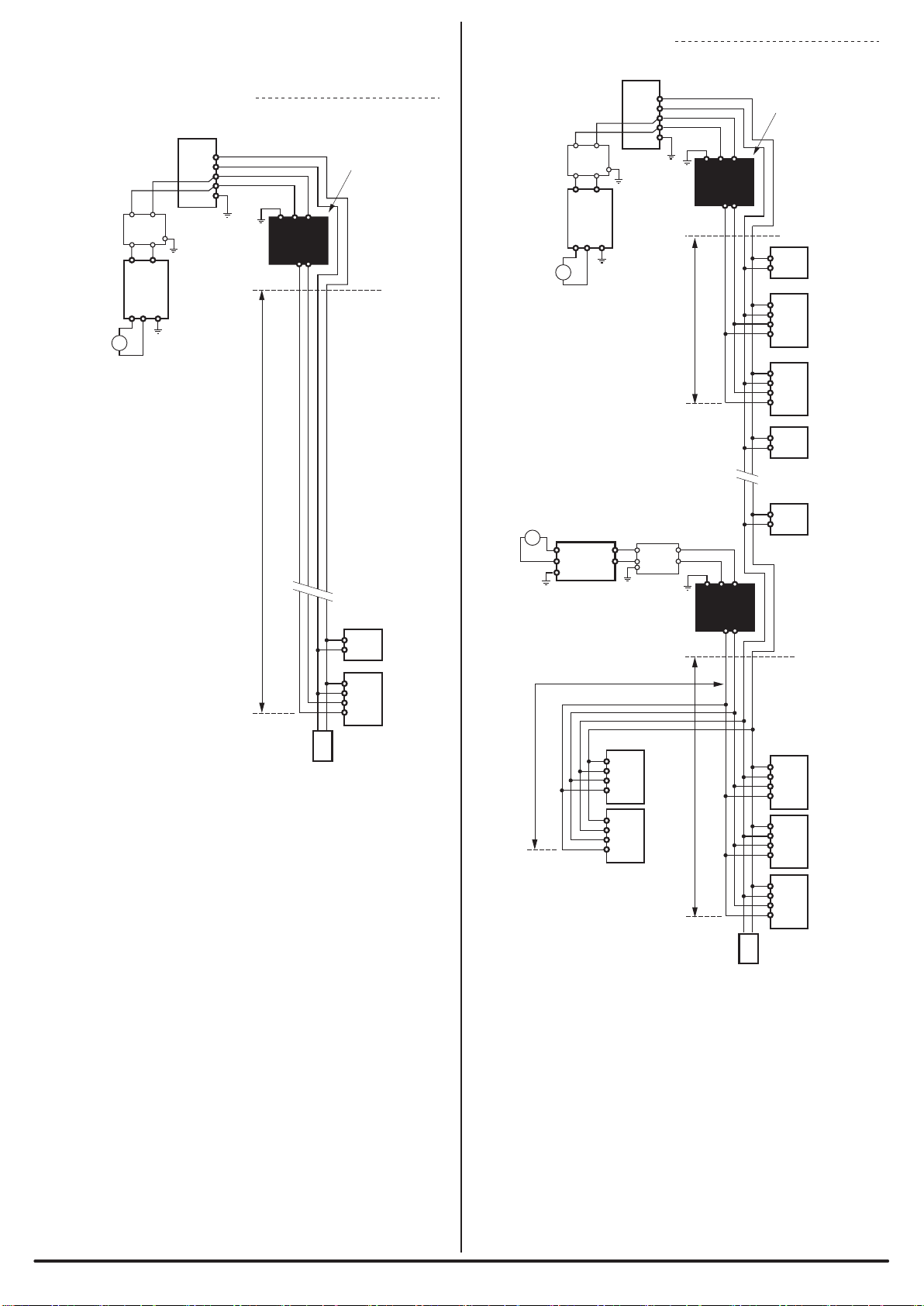
Bus type
(Multi-drop method, T-branch method, Tree branch method)
Connection mode
512 max. (IN: 256, OUT: 256)
Number of connection points
Up to 128 units
Number of units connected
RAS feature
■Individual specications
Consumption current
Number of occupied points
Mass
(This product/Cable)
Electromagnetic induction detection
Detection method
Shield type
Shield presence/absence
Non-magnetic metal/Magnetic metal
Detection target *3
Standard detection objects
Depends on parameter setting
Max. 10ms
Detection distance
Hysteresis
Response time *4
Detection distance at 23°C
Impact from
temperature
Impact from voltage
(At ambient temperature
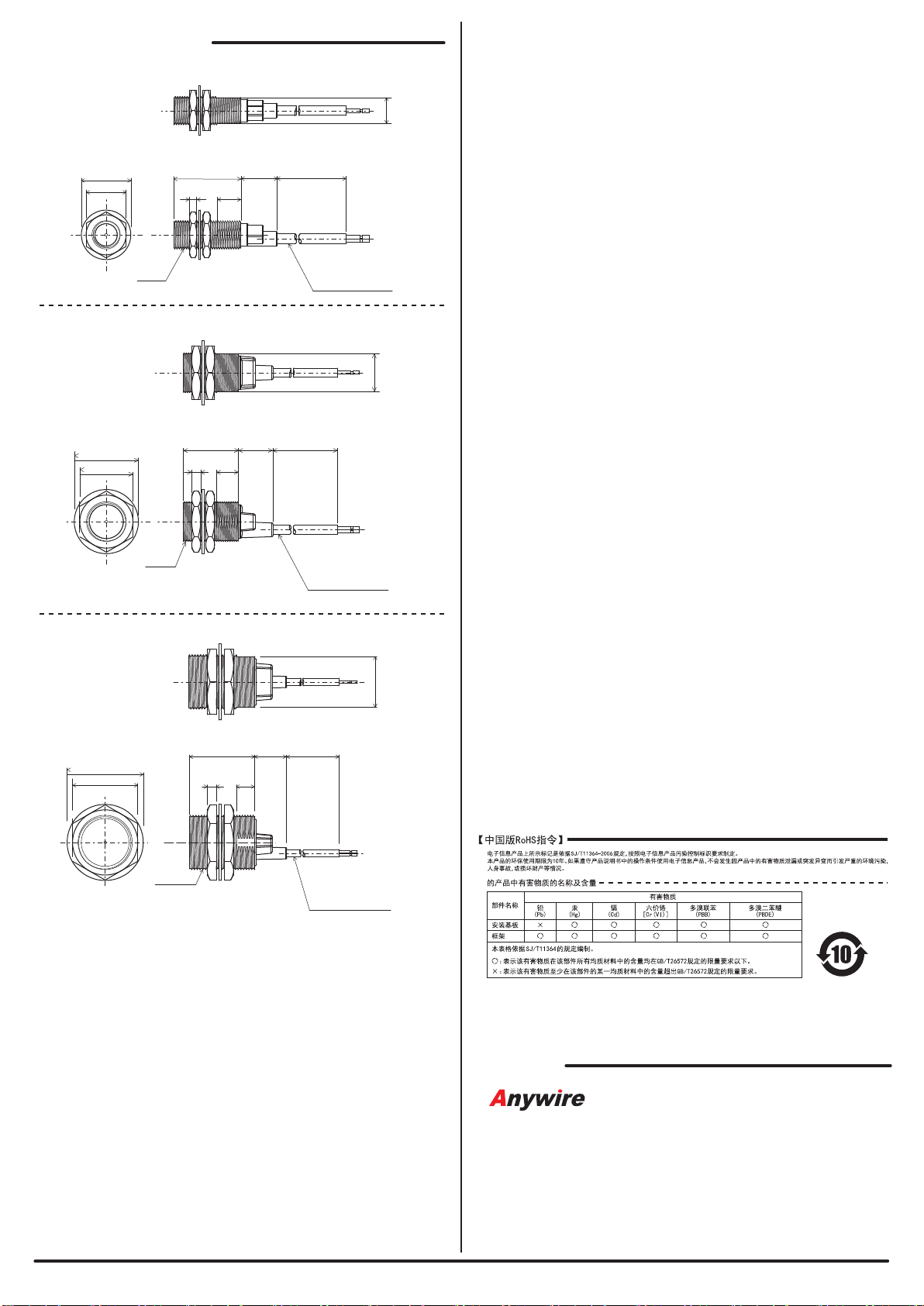
of 23°C) M18: 5mm (max.)
M18: Aluminum 18×18×3mm
M12: Approx. 37g
M18: Approx. 49g
M30: Approx. 105g
Mass
(Nuts/Washer)
M12: Approx. 8g
M18: Approx. 19g
M30: Approx. 41g
M12: Aluminum 12×12×3mm M30: Aluminum 30×30×3mm
M12: 2mm (max.) M30: 10mm (max.)
Stable detection
distance M18: 0 to 4.5mm
M12: 0 to 1.6mm M30: 0 to 9.0mm
M12: Within ±20%
M18: Within ±10%
M30: Within ±10%
IP67
Protective structure
Supplied via AnyWireASLINK transmission signal (DP, DN)
M12: 13mA
M18: 13mA
M30: 13mA
One-point input
*1 Do not use or store the AnyWireASLINK device in an environment pressurized equal to
or higher than the atmospheric pressure at an altitude of 0m. Doing so could cause a
malfunction.
*2 Index that indicates the occurrence of conductive material in the environment where
the device is used.
Contamination level 2 indicates that only non-conductive contamination occurs.
However, incidental condensation could create temporary conductivity in this
environment.
*3 The detection distance depends on the material.
*4 Time from when ON or OFF is detected until the transmission signal is transmitted.
The time combining this time and the transmission 2 cycle time is the transmission
delay time.
Transmission line disconnection detection,
transmission line short-circuit detection,
transmission power supply reduction detection,
ID redundancy, ID not set detection
Within ±1% of the detection distance with the
AnyWireASLINK master supplied power voltage
within range of 27.6 to 21.6V
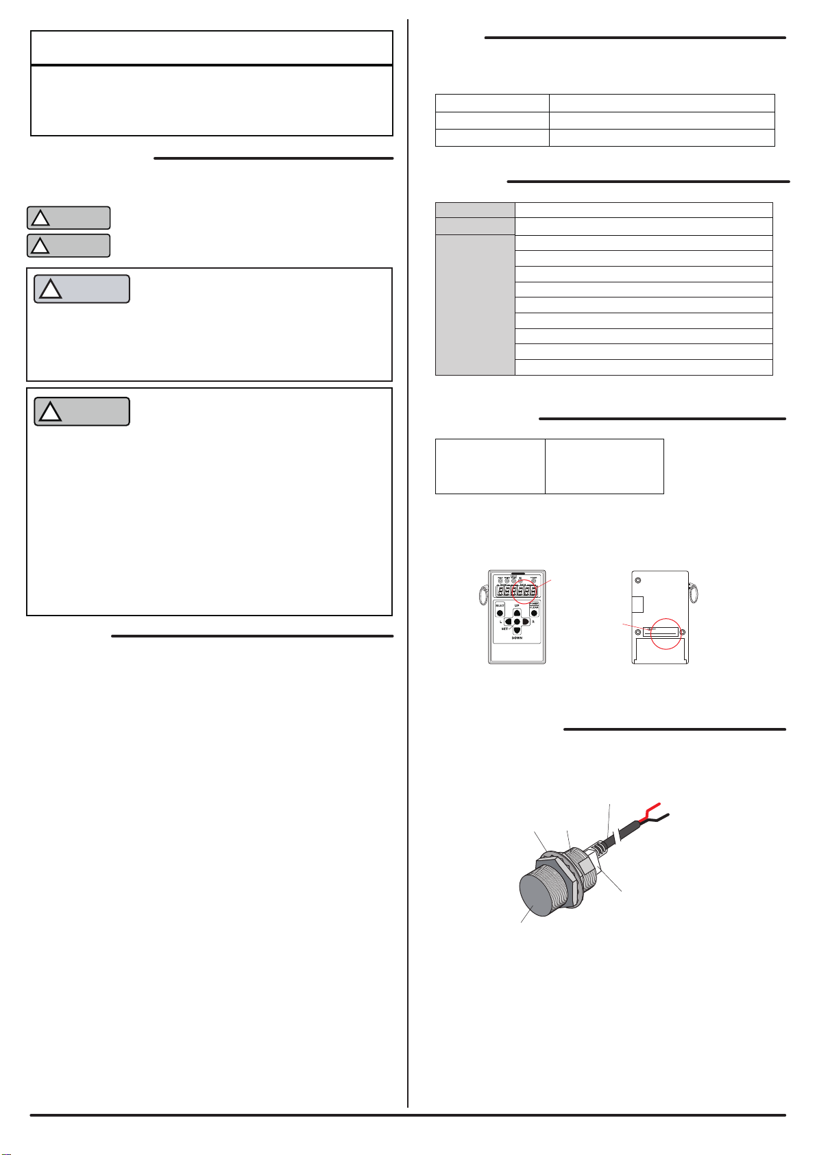
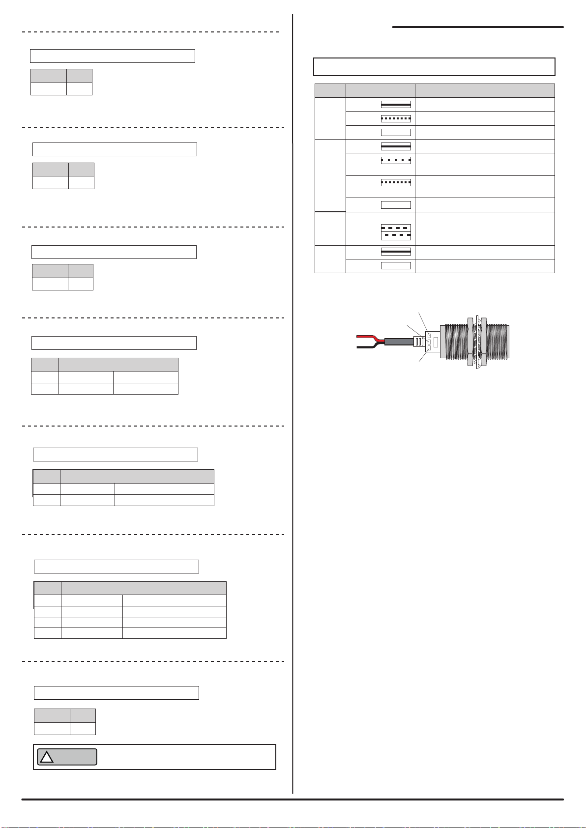
LINK IN ALM Cause Measures
○ ○ ○
Off Off Off
●
On
○
Off
○
Off
◎
Flashing
(0.5 seconds
alternately)
○
Off
◎
Flashing
(0.5 seconds
alternately)
- - ◎
Flashing
(On for
0.2 seconds,
off for
1.0 seconds)
◎ - ●
Flashing On
[Troubleshooting]
If the followings are displayed on the LEDs of this product, take
measures as shown below.
- ASLINKSENSOR is
not connected to an
AnyWireASLINK
system.
- Power supply for the
AnyWireASLINK
system itself is not
turned on.
-
Directly connected to
24-0V power supply.
- The ASLINKSENSOR
maintains the
address number 255
(default setting).
- The ASLINKSENSOR
has an address
redundant with
another unit.
- Transmission signal
level reduction has
been detected.
- The sensing level
has been reduced.
- Conrm that there is no
disconnection between the
ASLINKSENSOR and the
AnyWireASLINK system, and recover
the connection.
- Conrm the power status of the
AnyWireASLINK system, and turn on
the power.
- Re-connect to the AnyWireASLINK
system.
- Set any address number other than
255.
- Look for the other unit which has the
same error indication, and set any
address number different from it.
- Decrease the number of units
connected to the same
AnyWireASLINK system.
- Shorten the transmission line
between the ASLINKSENSOR and
the master unit.
- Conrm the ASLINKSENSOR status,
adjust the position, and clean the
detection surface.
◎ - ◎
Flashing
(0.1 seconds
alternately)
Flashing
- Teaching is not
normally operated.
- Make sure to perform teaching
operation again.
Take measures as follows in the following case.
Symptom Measures
Detection cannot be
performed.
Setting cannot be
performed with
the address writer.
Indication Cause Measures
[E-0303]
When the following error is indicated on the address writer, take
measures as shown below.
The set parameter is incorrect. Check the parameter and set the correct
parameter.
- Is the detected metal in the appropriate location?
→Make adjustments so that the detected metal is within an appropriate range
from the ASLINKSENSOR detection surface.
- Is wiring correct?
→Conrm that the ASLINKSENSOR transmission line is correctly connected
to the AnyWireASLINK transmission line (DP, DN).
- Are the AnyWireASLINK master unit and slave unit powered by a power supply
with the appropriate capacity?
→Conrm the power supply.
- Did you perform teaching?
→Perform teaching settings with the work that is actually detected.
- Are you using within the rated detection range?
→Use within the rated range.
- Is wiring correct?
→Reconrm the ASLINKSENSOR transmission line connection.
- Is power fed to the AnyWireASLINK system?
→Conrm the power supply.
- Is the set parameter correct?
→Check the parameter and set the correct parameter.
[Parameters and items]
Parameter Default
variable
Variable Details
[01.] M12 : 18
M18 : 24
M30 : 26
M12 : 19
M18 : 25
M30 : 27
Set the threshold of the sensing level
to judge presence/absence of detection.
0 - 100%
Threshold
[02.] 5
Set change amount of sensing level
required to turn detection state ON to OFF.
0 - 100%
Hysteresis
[03.] 80
Set an upper limit for the alarm
judgment value.
0 - 100%
Alarm value Hi
[04.]
Set a lower limit for the alarm
judgment value.
0 - 100%
Alarm value Lo
[05.]
50
Set a monitor time for the alarm
judgment value. (1 = 100ms)
3-255
Alarm value
monitor time
[06.]
0
Normally open
Normally close
0
Normally open/
Normally close
[07.]
0
Simple mode
Normal mode
0
Operation
mode
[10.]
0
Delay timer disabled
ON delay timer
Delay timer
ON/OFF
[11.]
0 - 255 Set the delay time. (1 = 10ms) 0
Delay timer
value
1
1
0
1
OFF delay timer
ON/OFF delay timer
2
3

-BSK4117M**1K 9/9-
[Address]
Anywire Corporation
:Contact by website http://www.anywire.jp
Headquarters :1 Babazusho, Nagaokakyo-shi, Kyoto 617-8550 JAPAN
Printed in Japan 2017 UMA-16717A-EN
[Outside Dimensions]
Unit: mm
BS-K4117-M18-1K
BS-K4117-M12-1K
BS-K4117-M30-1K
Transmission cable
(Oil-resistant,
ex-resistant type)
φ29
24
(1000)15.535
4 10
17
M18X1
Red: DP
Black: DN
Transmission cable
(Oil-resistant,
ex-resistant type)
Red: DP
Black: DN
φ21
17
35.5
3 10
15.4 (1000)
11
M12X1
10
5
Red: DP
Black: DN
M30X1.5
43
36
φ42
17.6 (1000)
Transmission cable
(Oil-resistant,
ex-resistant type)
28
This manual suits for next models
3
Table of contents
Other Anywire Accessories manuals
Popular Accessories manuals by other brands

PCB Piezotronics
PCB Piezotronics 137B27 Installation and operating manual

Gewiss
Gewiss GW 20 641 manual

Hudora
Hudora 65410 INSTRUCTIONS ON ASSEMBLY AND USE

Avery Weigh-Tronix
Avery Weigh-Tronix ZK830 User instructions

Larson Electronics
Larson Electronics SLEDB-110V-30C-XMS quick start guide

IFM Electronic
IFM Electronic efector 600 OWF installation instructions