-B284SB0*1K**P30 1/16-
Ver.1.1
B284SB-0□-1K□□P30
A
1
B
2
C
3
D
4
E
5
F
6
G
7
H
8
I
9
J
10
K
11
L
12
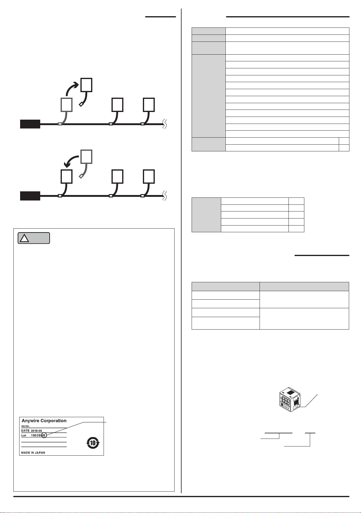
Lot No. 19ECBNB
WARNING
!
WARNING
!
CAUTION
!
CAUTION
!
AnyWireASLINK System Products Guide
[Type]
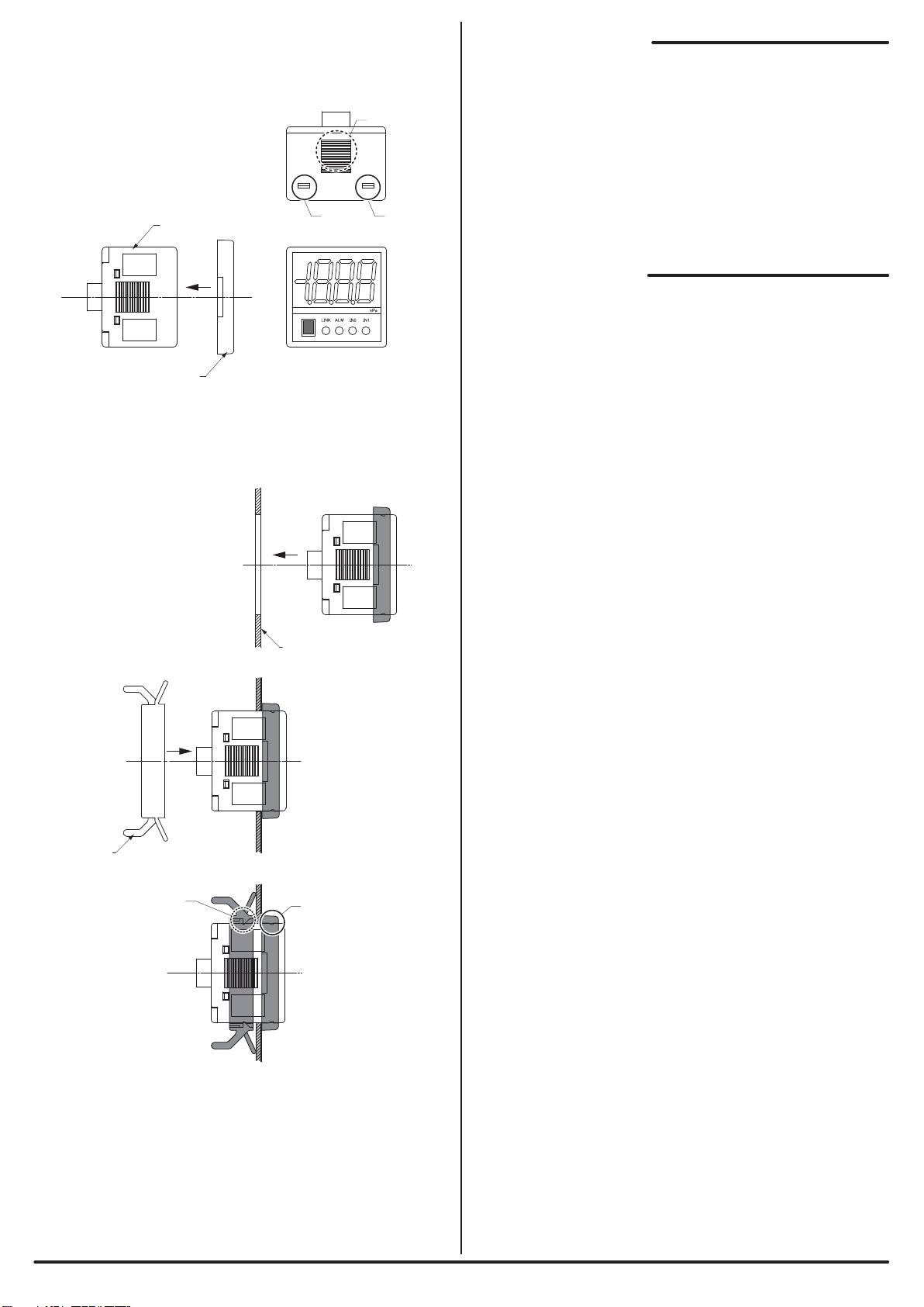
ASLINKSENSOR [ASLINK Sensor]
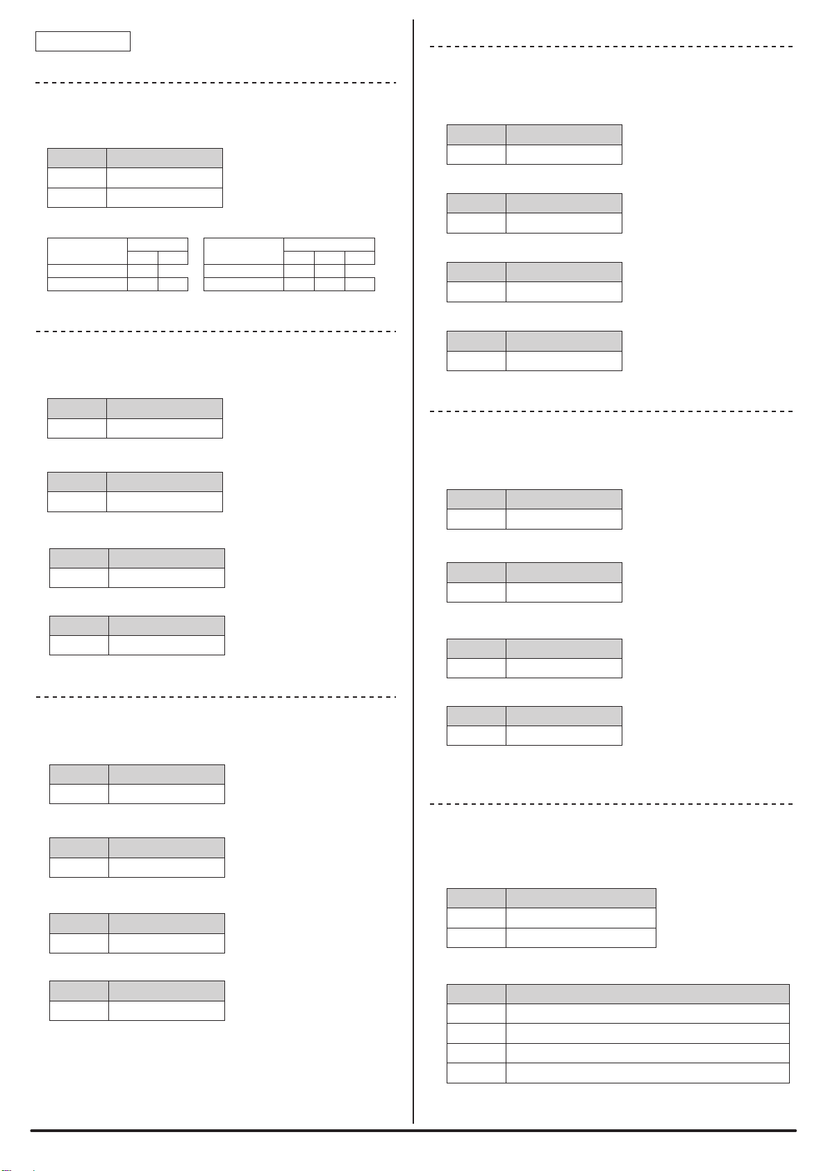
B284SB-01-1KPP30 Bit input: 1 point
Bit input: 2 points
Bit input: 1 point
Bit input: 2 points
Bit input: 1 point
Bit input: 2 points
Bit input: 1 point
Bit input: 2 points
B284SB-02-1KPP30
B284SB-01-1KNP30
B284SB-02-1KNP30
B284SB-01-1KLP30
B284SB-02-1KLP30
B284SB-01-1KPLP30
B284SB-02-1KPLP30
Positive pressure
(0 to 1000kPa)
Negative pressure
(0 to -100kPa)
Compound pressure
(-100 to 100kPa)
Low positive pressure
(0 to 100kPa)
○System Safety
This system is intended for general industrial applications. It
does not have functions for supporting applications requiring
higher levels of safety such as safety-related devices or
accident prevention systems. The product must not be used for
these purposes.
○Always turn off the power in installing or replacing the system.
○Prolonged continuous flow of a rated load current or higher or
a transit current due to load short-circuit, etc., in the hybrid unit
including the output unit and the output circuit may result in
smoking or firing. An external safety device such as a fuse
must be installed.
■Warranty period
The warranty on the delivered Product shall continue to be effective for one (1) year
after the delivery thereof to a location as designated by the original owner.
■Scope of warranty
Should a defect occur in any part of the Product during the foregoing warranty
period when it is used normally in accordance with the specifications described in
this Products Guide, the Company shall replace or repair the defect free of charge,
except when it arises as a result of:
[1] Misuse or abuse of the Product by the owner;
[2] Fault caused by other than the delivered Product;
[3] The unauthorized modification or repair of the Product by any person other than
the Company’s personnel;
[4]
Any unusual force of nature, disaster or other cause beyond the Company’s control.
○System power supply
Use a stable, 24V DC power supply. Use of an unstable power
supply may cause problems with the system.
○Separately route high-voltage and power cables
Although the AnyWireASLINK has a high noise margin, install
the transmission line and I/O cables away from high-voltage
and power cables.
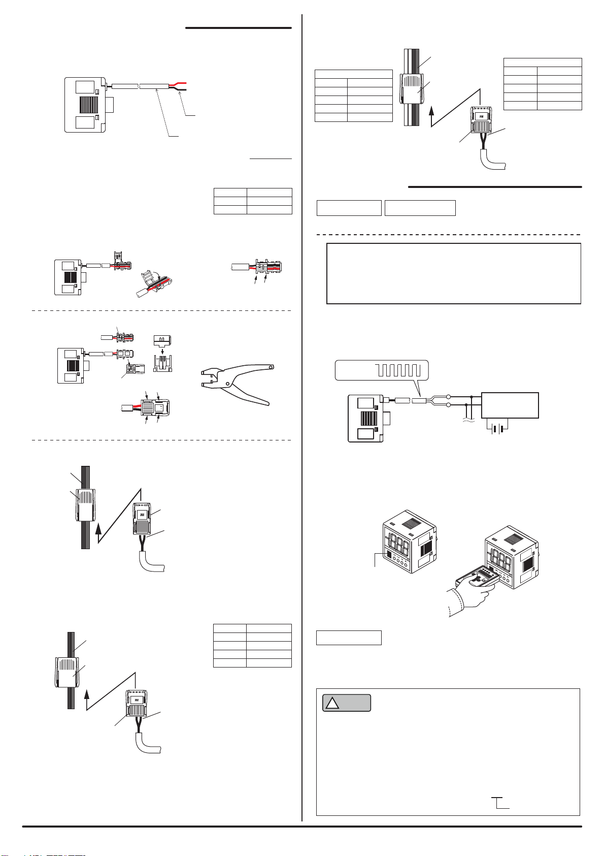
○Connectors and terminals
- Consider the length and securing method of cables so that
the cables and connectors would not be subjected to any
stress and, even if they are under stress, they would not
become loose.
- Make sure to prevent any metal objects from getting inside
the connectors or the terminal blocks.
- Short-circuits caused by metal objects or mis-wiring are likely
to damage the device.
○Do not impose any external loads on the units. Doing so may
cause a failure.
○Do not disconnect or reconnect between the transmission
line and slave units when the transmission line is active. A
malfunction may occur.
○Use the AnyWireASLINK within the range of the specifications
and conditions shown below.
[Notes on Safety]
[Warranty]
Precautions that must be observed in order to use this system safely are indicated as
shown below.You must observe these precautions.
A WARNING indicates a potentially hazardous situation which, if not
handled correctly, could result in death or serious injury.
A CAUTION indicates a potentially hazardous situation which, if not
handled correctly, may result in personal injury or property damage.
*If you set equipment parameter 1 (alarm bit) to “enabled,” the number of occupied bit input
points is increased by one.
■Note on use ⇒A separate Address Writer is required to set addresses
and other data.
*
For more information, refer to [Various Settings] on page 8.
New functions have been added to AnyWireASLINK products in May 2019
onward. Also, for the purpose of differentiation of compatible functions,
indication of product lot number (lot No.) has been changed.
Compatible functions vary depending on lot No. Please understand the following
description thoroughly to use each product.
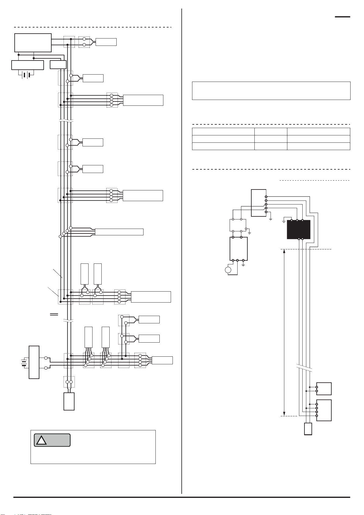
The master unit compatible with the word transmission function provides areas for
transmission and receiving of word data (numerical information) such as analog
data and sensing level data.
Using this function enables reduction of occupancy of bit information area by word
data.
To enable word transmission, it is necessary that the system should be configured
only with slave units compatible with the word transmission function.
A slave unit incompatible with the word transmission function cannot be connected
to the AnyWireASLINK system to conduct word transmission.
For slave units that handle word data, word address settings are required.
[About Lot No.]
[About Pictogram*4]
Functions added to Ver. 1.1 are as follows:
The term “warranty,” as used herein, refers to the warranty applicable to the
delivered product alone. The Company shall not be liable for consequential or
incidental damages resulting from any malfunction.
■Repair at cost
After the expiration of the warranty period, the owner shall be responsible for all
costs and expenses incurred for the troubleshooting and repair of the Product. Even
during the warranty term, the Company shall repair any defects arising from causes
other than within the scope of the warranty as specified above, at the owner’s cost.
■Changes in the product specifications and the descriptions in the manual
The descriptions in this manual may be subject to change without notice.
[About AnyWireASLINK Ver. 1.1]
*1 To use these functions, a master unit compatible with each function is required.
For details, refer to this manual together with the manual for the master unit.
*2 You can use this function with the word-transmission AnyWireASLINK system connected.
To handle word data, word address settings are required for slave units.
It depends on slave units whether word address setting is enabled or not.
Single unit simplified replacement*1
Word transmission*1*2
Functions available with Ver. 1.1
“19E” means May 2019.
Alphabet
Month
*3 Some products have no indication of function version.
Ver. 1.0*5
Compatible with
Ver. 1.1
*4 The pictogram may not be marked (or stuck) depending on the product.
*5 AnyWireASLINK device not compatible with Ver. 1.1 (word transmission and single unit
simplified replacement functions)
Some products, not marked with the Ver. 1.1 pictogram, are compatible with the
functions included in Ver. 1.1. Refer to the lot No. and the product guide for ultimate
confirmation.
[About Word Transmission]
S/W version
H/W version
Function version*3
Example:
Year and month
Year: Numbers
(Lower two digits of the Christian era)
Month: Alphabet (as per the table below)
As a result of the addition of functions, indication of lot No. has been changed
from 3 digits (conventional format: year and month only) to 6 digits or 7 digits.