AOR LA400 User manual

MAGNETIC LOOP ANTENNA
L
A400
Instruction manual
AOR Ltd.
Authority On Radio Communications

2
-

3
Table of contents
1. Introduction . . . . . . . . . . . . . . . . . . . . . . . . . . . . . . . . . . . . . . . . . 4
2. Included in this packa e . . . . . . . . . . . . . . . . . . . . . . . . . . . . . . . . . 5
3. Hardware setup . . . . . . . . . . . . . . . . . . . . . . . . . . . . . . . . . . . . . . 6
4. Operatin instructions . . . . . . . . . . . . . . . . . . . . . . . . . . . . . . . . . . 7
5. Remote tunin system . . . . . . . . . . . . . . . . . . . . . . . . . . . . . . . . . 9
6. Directivity of a loop antenna . . . . . . . . . . . . . . . . . . . . . . . . . . . . . 10
7. Characteristics of a “shielded” loop antenna . . . . . . . . . . . . . . . . 11
8. Options . . . . . . . . . . . . . . . . . . . . . . . . . . . . . . . . . . . . . . . . . . . . . 12
9. Specifications . . . . . . . . . . . . . . . . . . . . . . . . . . . . . . . . . . . . . . . . 13

4
1. Introduction
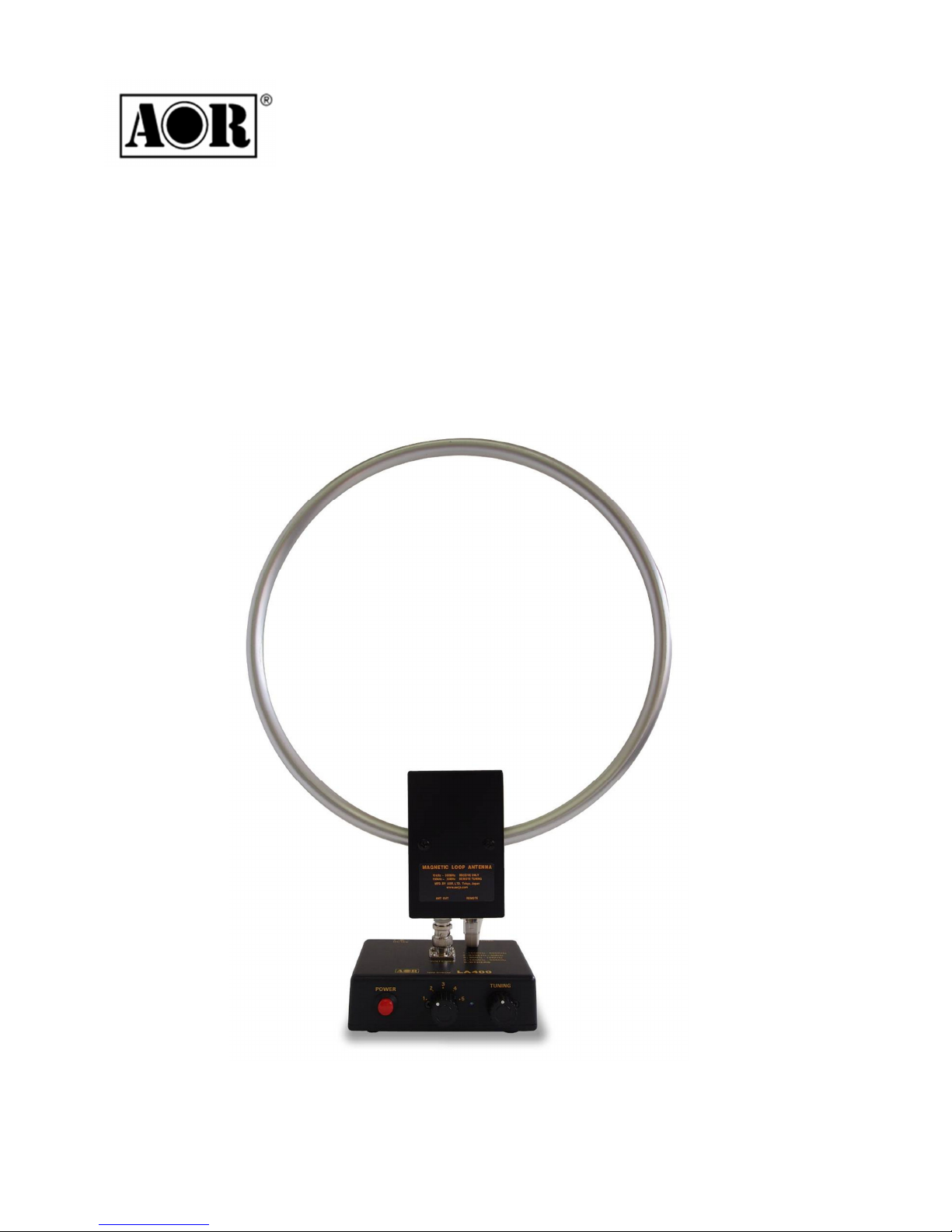
Thank you for purchasin the LA400 Ma netic loop antenna.
To et the best possible results from your LA400, we recommend that you read this manual
and familiarize yourself with the antenna.
Since the invention of this revolutionary concept by KOLSTER in 1915, loop antennas,
especially of the active type, have also been widely used by the military in the 70’s, before
becomin very popular amon hobby listeners.
In recent years, the increase in man-made local noise (typical city noise) poses a problem
for the reception of distant si nals in the lon wave, medium wave and shortwave bands.
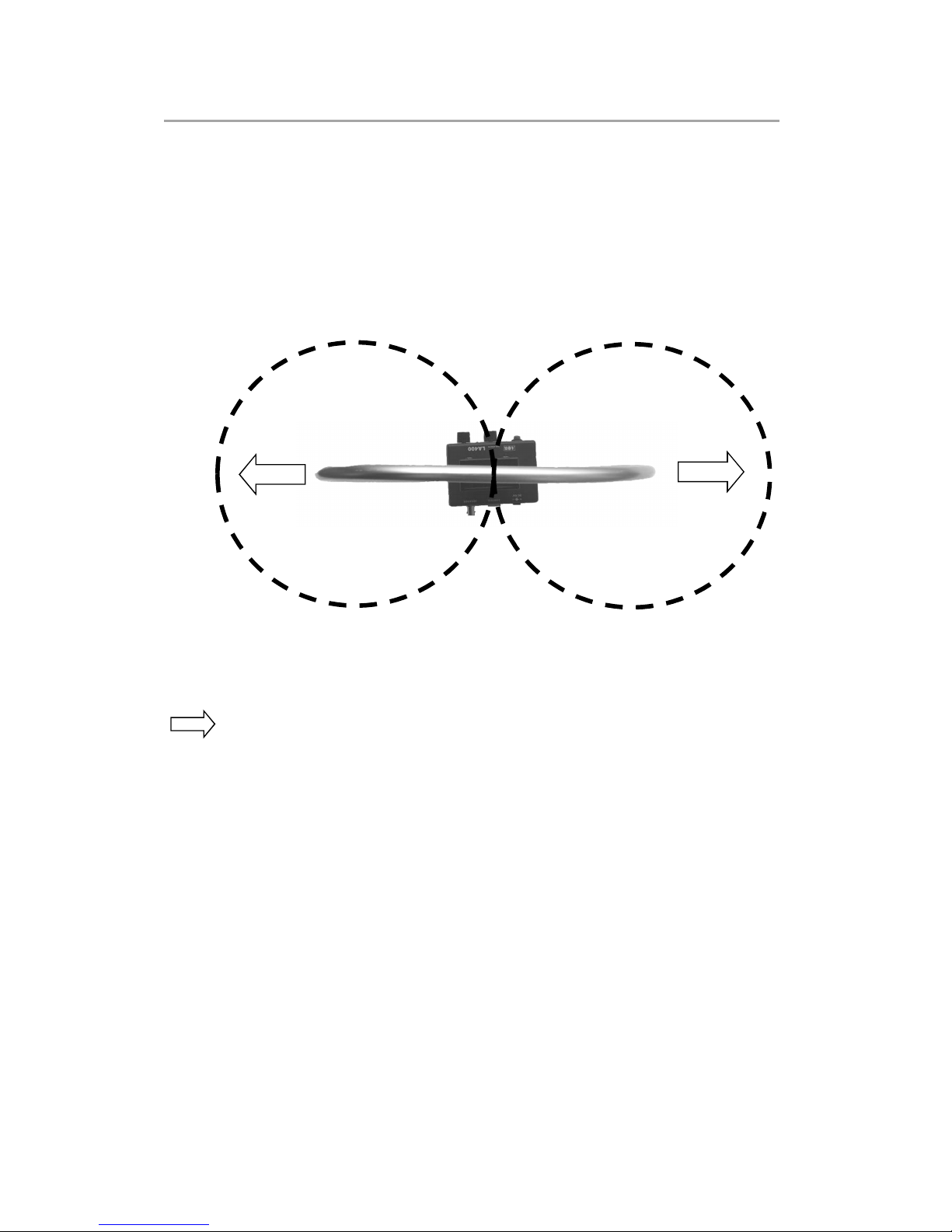
LA400 is our latest product based on the technolo y we developed since the ori inal LA320
loop antenna. In addition to its exceptional directivity in order to minimize the effects of local
noise, the revolutionary LA400 offers, with its REMOTE TUNING SYSTEM, the perfect
solution to keep the antenna away from noise sources by settin it up in quiet areas!
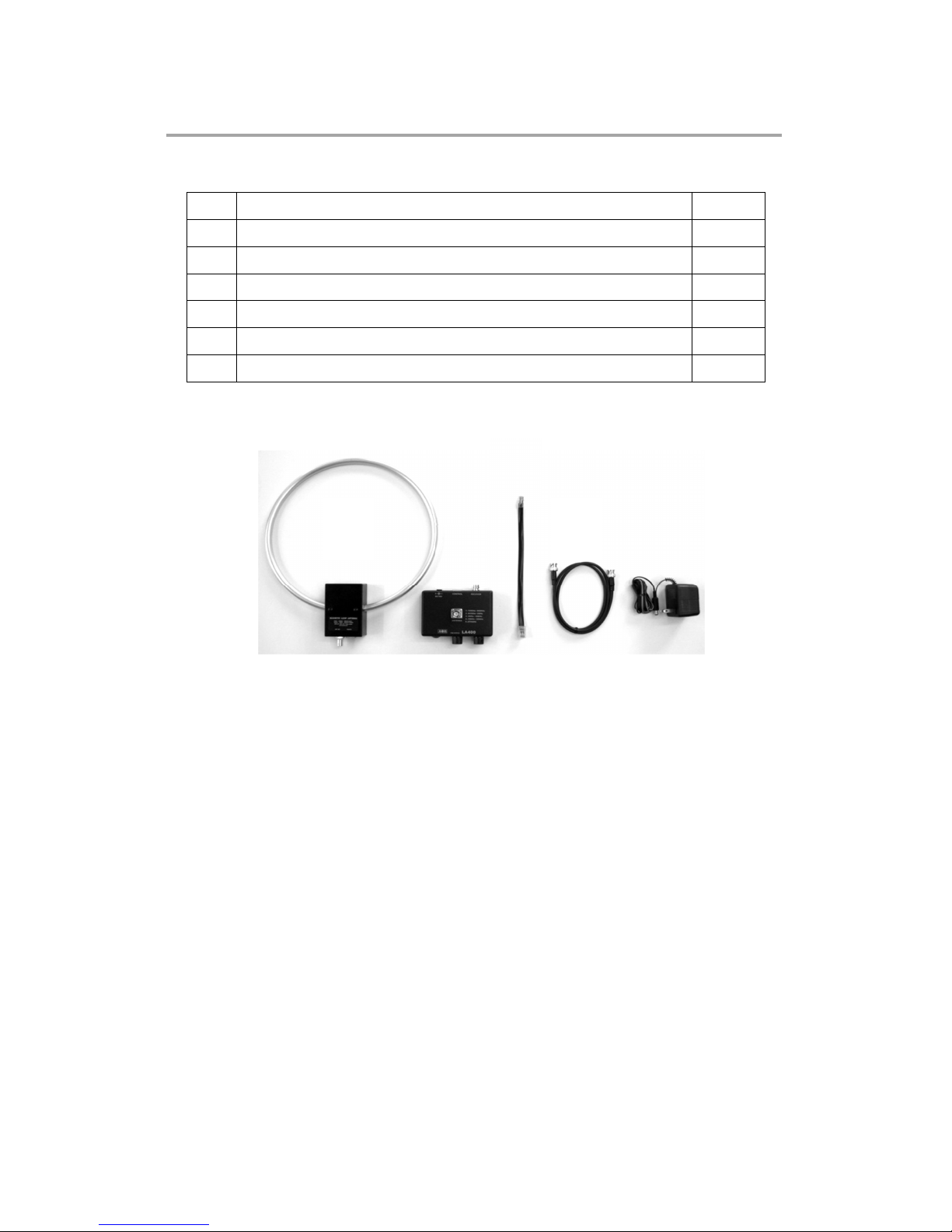
While the control (tunin ) box stays at hand’s reach, the loop element can be set away by
usin simple LAN and BNC coaxial cables.
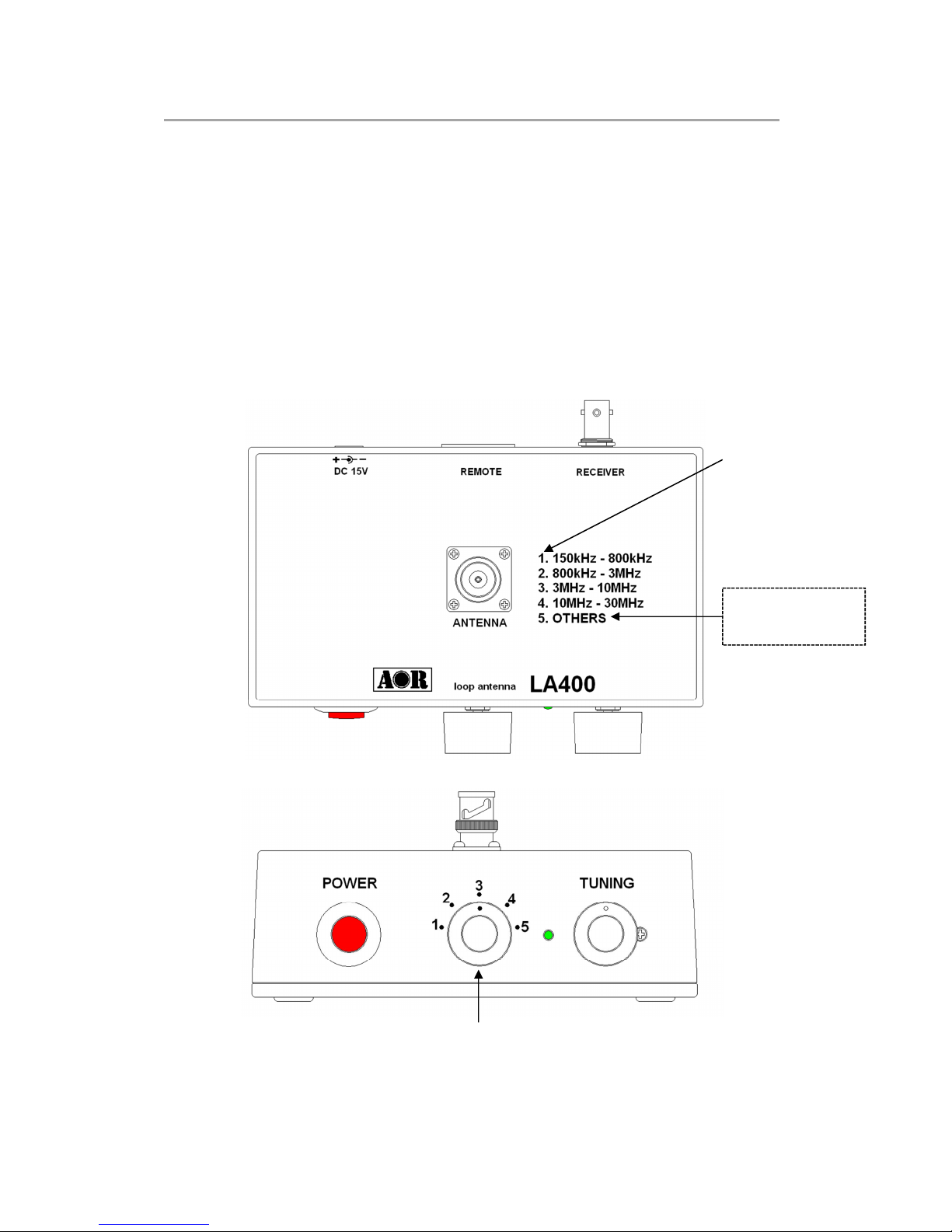
10kHz to 500MHz, 5 position band switch to peak only on the wanted si nal. Small size
30.5cm diameter loop with exceptional 20dB ain
Remote tuning – Unlike previous amplified indoor loop antennas, the band switchin and
fine tunin controls are not tied anymore to the loop element. With these controls now on
the control box and by usin the LA400-RCK optional extension cables, it is now possible
to tune the antenna while the loop element is setup at the most reception friendly location
possible (window, covered balcony, etc...). Compatible with 3rd party cables. Maximum
len th: 20m. (Minimum input volta e 12V when usin an extension)
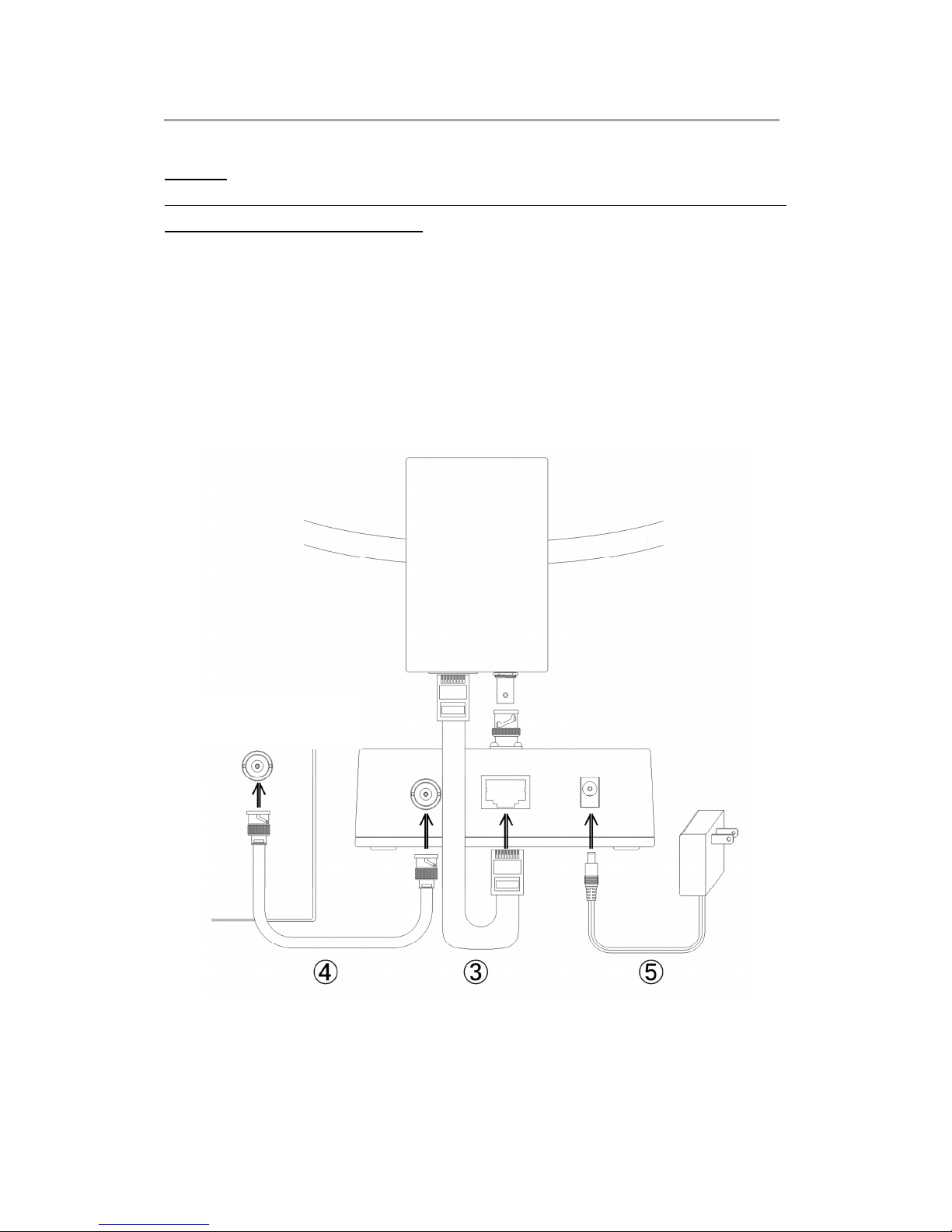
A relay system is used for band switchin , providin excellent isolation characteristics.
The relay is efficiently placed inside the loop element, while you can operate it throu h the
control box via the control cable.
Electronic tuning from 150kHz 〜30MHz allows very sharp tunin to the desired
frequency. Shift the ali nin point sli htly to attenuate unwanted si nals while amplifyin
the wanted si nal.

5
2. Included in this package
No.
Description Qty
① Loop element 1
② Control box 1
③ Control cable (LAN type) 30cm 1
④ 1m coaxial cable (RG-58U with BNC (F)/BNC (F) connectors) 1
⑤ AC power supply 1
⑥ This printed instruction manual 1
⑤
⑤⑤
⑤
④
④④
④
①
①①
①
②
②②
②
③
③③
③

6
3. Hardware setup
Caution!
LA400 is a RECEIVE ONLY antenna. Do not transmit with it or its circuitry will be severely
dama ed, maybe even beyond repair.
As explained on the dia ram below, attach the loop element to the control box, then connect
the coaxial and control cables. Finally, connect the AC power supply.
To connect LA400 to an antique receiver with 600Ω antenna terminal, use the optional
MC-600 Impedance Matchin Transformer.
Coaxial cable Control cable AC power supply
Control box
②
②②
②
Loop element
①
①①
①
To antenna input socket
of your receiver

7
4. Operating instructions
◎ Connect the AC power supply and push the red power button on the control box. A blue
LED will li ht up.
◎ Tune your receiver to the desired frequency.
◎ Now you need to select one of the 5 available band ran es, usin the band switch
numbered from 1 to 5. Refer to the printed switch number / band ran e information on
the top of the control box.
Please note that position 5 is non-tunable, as the loop is wired to act as an amplified
whip antenna.
Band switch
10kHz to 150kHz
&
30MHz to 500MHz.
5 selectable bands

8
◎ Peak the received si nal by turnin the TUNING knob slowly to either the left or the ri ht.
The white dot on the tunin know helps you to see the approximate location of the tunin .
For your reference, when the dot is on top as on the above illustration, the tunin PEAK
is approximately in the middle of the selected band.
For example for band switch position 3 (3MHz to 10MHz), it would be rou hly peaked on
6.5MHz.
Tunin is most critical above 3MHz. For best performance of LA400 and optimal
reception conditions, make sure the selected band is appropriate for the received
frequency, and search for the si nal peak with the tunin knob.
◎ A loop antenna is very directional. Rotate the loop element until your receiver’s si nal
stren th meter (S-meter) deflects to maximum and the incomin si nal sounds clearest.
If your receiver does not have an S-meter, simply adjust for maximum received si nal.
Rotate the loop element until the si nal is stron est and any interferin si nal is nulled.

9
5.Remote tuning system
With its unique REMOTE TUNING SYSTEM, the band switchin and fine tunin controls are
not tied anymore to the loop element. With these controls now on the control box and by
usin the optional LA400-RCK extension cables, it is now possible to tune the antenna while
the loop element is setup at the most reception friendly location possible (window, covered
balcony, etc...).
You can of course use eneric strai ht LAN and RG-58U 50Ω coaxial cables. Maximum
len th: 20m each. Minimum input volta e 12V when usin an extension.
Please note that TUNING knob positions mi ht vary dependin on the len th of the remote
cables. This is due to sli ht variations of the volta e supplied to the loop element, dependin
on the len th of the remote cables. This is not a malfunction and does not diminish the
antenna’s performance.
For optimal reception conditions, always try to setup the loop antenna as far away as
possible from noise sources such as switchin power supplies, TVs, computers, etc
Ideal locations to remotely setup the loop element are
windows, curtain rails and even better, covered balconies, as
lon as the loop element does not et wet!
Remember that LA400 is NOT WATERPROOF!
It is hi hly advised to put the loop antenna back indoors, after
use.
For window mountin , it is a ood idea to use a
(non-supplied) plastic suction hook, as illustrated here.
Alternatively you can also use a (non-supplied) nylon cord to
han it to a curtain rail.

10
6. Directivity of a loop antenna
A si nificant advanta e of a loop antenna is its directional pattern, a “fi ure 8” shape with
two null points separated by 180 de rees. The null in reception that is located at ri ht an les
to the plane of the loop can be used for interference reduction. On the other hand, received
si nal stren th is reatest in the directions indicated by the arrows.
Horizontal radiation pattern of LA400
NULL
NULL
NULL: An le from which ma nitude of the radiation pattern decreases to zero. In other words, these are the
sides from which the antenna receives the least.
Maximum reception performance is achieved when these sides of the loop face the si nal.

11
7. Characteristics of a “shielded” loop antenna
A shielded loop antenna is less susceptible to nearby electrical interference sources, thanks
to the electrostatic shieldin of the loop afforded by the rounded metallic conduit enclosin
the wire coils.
By these principles, LA400 responds to the ma netic field rather than the electric field, thus
efficiently isolatin the low frequency electrostatic noise from the distant si nal to be
received.
Shield circuit of LA400
With this desi n, all parts of the loop will have the same capacitance to round. The shield
also protects the loop from the induction field created by nearby disturbances. The induction
field refers to the electric and ma netic fields in the immediate vicinity of an antenna. Those
fields decrease rapidly in stren th with distance, and the induction field is usually i nored.
However, wires and other metal objects near the loop can take ener y from a passin wave
and produce induction fields that can induce spurious volta es in the loop.
A shield over a loop antenna will not appreciably decrease the amount of ma netic flux that
passes throu h the loop when a wave oes by - as lon as it does not form a complete turn.
A ap is left in the shield so that it does not become a shorted turn. Without the ap, the
shield would reduce the ma netic field linkin the loop so that no si nal could be received by
the internal wire. With the ap, alternatin currents can be induced in the metal shield and
volta es will be induced in the internal wire.

12
8. Options
LA 00-RCK Extension cables (10m each)
This set of cables allows you to separate the
control (tunin ) box from the loop element, by up
to 10m. Conveniently place the loop element as
closely as possible to an open space, such as
window, covered balcony, etc...away from local
electrical noise, for a quieter reception
experience.
MC-600 Impedance matchin transformer
Passive impedance matchin transformer interface which allows
your LA400 to be connected to any antique receiver with a 600Ω
antenna terminal. Supported frequency ran e: 10kHz to 30MHz.
MC-600 has the same isolation feature than the GT-1 accessory
described below.
GT-1 Galvanic isolation transformer
To be connected between the receiver and the LA400 antenna.
Does reatly reduce local noise by breakin the round loop
effect between antenna and receiver, especially when the
LA400-RCK 10m separation cables are used.
Supported frequency ran e: 40kHz to 30MHz

13
9. Specifications
LA 00 Magnetic loop antenna
Frequency ran e 10kHz 〜 500MHz
Ali ned ran e 150kHz 〜 30MHz 4 band selectable
Unali ned ran e 10kHz 〜 150kHz, 30MHz 〜 500MHz
Gain 20dB min.
Operatin temp. -10℃ 〜 +60℃
Power req. 9〜15V DC, 80mA @ 12VDC
(Min. input volta e 12V when usin an extension)
Impedance 50Ω
Sizes (mm)
projections incl.
Loop 305mm diameter
Loop element 305(W)x367(H)x38(D)
Control box 118(W)x59(H)x112(D)
All assembled 300(W)x425(H)x110(D)
Wei ht Loop element 220
Control box 300
Supplied
accessories
Control cable (LAN type) 30cm
AC power supply
BNC (F)/BNC (F) RG-58U coaxial cable (1m)
Printed user manual
LA 00 is NOT intended for transmit purposes!
Not waterproof, use only indoors.
Product specifications and desi n subject to chan e without prior notice.

14
Memo:
-

15
-

16
®
AOR Ltd.
2-6-4 Misuji, Taito-ku, 111-0055 Tokyo, Japan
www.aorja.com
Authority On Radio Communications
(Sept.25, 2013)
-
Other manuals for LA400
2
Table of contents
Other AOR Antenna manuals
Popular Antenna manuals by other brands

OmniMetrix
OmniMetrix TrueGuard-2 installation guide

Listen Technologies
Listen Technologies LA-116 manual

Sirio Antenne
Sirio Antenne SD 27 Dipole installation manual

Hama
Hama 69044276 Operating instruction

Philips
Philips US2-MANT901 - Tv Antenna Uhf/vhf/fm/hdtv... user manual

urmet domus
urmet domus 3000/087 quick guide