manuals.online logo
Brands
  1. Home
  2. •
  3. Brands
  4. •
  5. SteppIR
  6. •
  7. Antenna
  8. •
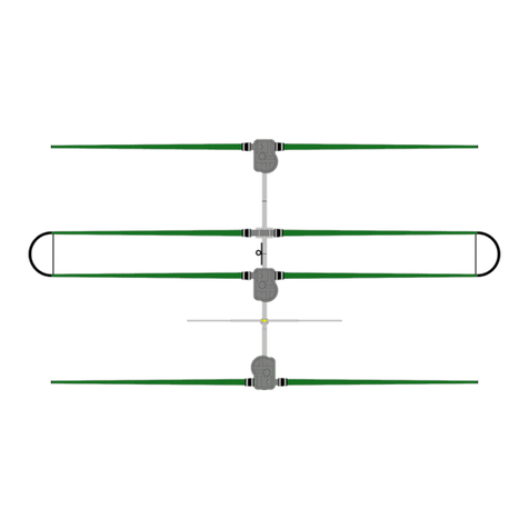
  9. SteppIR 3 Element Yagi User manual

SteppIR 3 Element Yagi User manual

1
3 Element Yagi Instruction Manual
Revision 3.81 05/22/2023
13406 SE 32nd St, BELLEVUE WA, 98005 WWW.STEPPIR.COM TEL: (425)-453-1910
2
SteppIR - Why Compromise?
The SteppIR antenna was originally conceived to solve the problem of covering the six ham
bands (20m, 17m, 15m, 12m, 10m and 6m) on one tower without the performance sacrifices
caused by interaction between all of the required antennas.
Yagi’s are available that cover 40 meters through 10 meters by using interlaced elements or
traps or log periodic techniques, but do so at the expense of significant performance reduction
in gain and front to back ratios. With the addition of the WARC bands on 30m, 17m and 12m,
the use of interlaced elements and traps has clearly been an exercise in diminishing returns.
Obviously, an antenna that is precisely adjustable in length while in the air would solve the fre-
quency problem, and in addition would have vastly improved performance over existing fixed
length Yagi’s. The ability to tune the antenna to a specific frequency, without regard for band-
width, results in excellent gain and front to back at every frequency.
The patented folded dipole loop elements on the DB36 allow for outstanding performance on
40m and 30m with element lengths that are 40% shorter than a full sized Yagi—at the expense
of only 0.3dB of gain!
The SteppIR design was made possible by the convergence of determination and high tech
materials. The availability of new lightweight glass fiber composites, Teflon blended thermo-
plastics, high conductivity copper-beryllium and extremely reliable stepper motors has allowed
the SteppIR to be a commercially feasible product.
The current and future SteppIR products should produce the most potent single tower antenna
systems ever seen in Amateur Radio! We thank you for using our SteppIR antenna for your
ham radio endeavors.
73 and good DX!
John Mertel
John Mertel
President/CEO
WA7IR
3
SteppIR Design
Currently, most multi-band antennas use traps, log cells or interlaced elements as a means to cover sev-
eral frequency bands. All of these methods have one thing in common–they significantly compromise
performance. The SteppIR™ antenna system is our answer to the problem. Yagi antennas must be
made a specific length to operate optimally on a given frequency.
So, instead of trying to “trick” the antenna into thinking it is a different length, or simply adding more
elements that may destructively interact, why not just change the antenna length? Optimal perfor-
mance is then possible on all frequencies with a lightweight, compact antenna. Also, since the Step-
pIR can control the element lengths, a long boom is not needed to achieve near optimum gain and front
to back ratios on 20 - 10 meters.
Each antenna element consists of two spools of flat copper-beryllium tape conductor (.54” Wide
x .008” Thick) mounted in the element housing unit. The copper-beryllium tape is perforated to allow
a stepper motor to drive them simultaneously with sprockets. Stepper motors are well known for their
ability to index very accurately, thus giving very precise control of each element length. In addition,
the motors are brushless and provide extremely long service life.
The copper-beryllium tape is driven out into a hollow fiberglass elements support tube (see below),
forming an element of any desired length up to the limit of each specific antenna model (a vertical uses
only one side). The fiberglass elements support tubes (poles) are telescoping, lightweight and very du-
rable. When fully collapsed, each one measures approximately 57” in length. Depending on the mod-
el, there may be additional extensions added to increase the overall element length.
The ability to completely retract the copper-beryllium antenna elements, coupled with the collapsible
fiberglass poles makes the entire system easy to disassemble and transport.
The antenna is connected to a microprocess
Boom
Element Housing Unit
Element Support Tube
Stepper Drive Motor
Copper Beryllium Tape
Copper-Beryllium Tape
4
*Projected area 10.73 sq ft / 0.996 sq m 14.37 sq ft / 1.34 sq m
*Projected area is the total perpendicular surface area measured in square feet/square meters, that is exposed to
wind. To calculate wind load you always take the largest projected area whether that is from the perspective per-
pendicular to the boom or perpendicular to the elements. In the case of SteppIR Yagi's, the maximum projected
area will always be the sum of the surface area's perpendicular to the Yagi elements. This calculation is a constant
number and will not change regardless of EIA specification changes. Do not mistake this projected area calculation
as anything more than a datapoint to present to your structural engineer, tower manufacturer or rotator manufac-
turer so that they can determine what is necessary for your application.
When sizing an antenna to a tower, many factors need to be taken into consideration including, but not limited to:
projected area of antenna in square feet or square meters, weight of the antenna and other items on tower, turning
radius, element lengths, antenna height, location exposure category, locations three-second gust wind-speed, loca-
tions maximum radial ice loading.
Improper specification of an antenna or rotator to a tower can result in product failure, injury or death. SteppIR is
not an expert on tower or rotator sizing and for this reason will never offer any recommendation – this specification
process is meant for industry professionals such as a structural engineer, tower manufacturer or rotator manufac-
turer. Please do not attempt to self-specify our products – the information provided by SteppIR is to be utilized by
industry professionals only and we will not accept any liability for improperly specified antenna/tower/rotator appli-
cations.
5
Topic Page
SteppIR Design 2-3
Specifications 4
Bill of Materials 6—8
Before you begin 9-10
Antenna Direction 11
Boom preparation 12-13
Wiring 14-19
Mounting the EHU’s to antenna boom 20-21
Preparation of the telescoping poles 22-30
Attach the poles to the EHU 31
6m passive element 32
Element truss (40/30 Loop) 33-38
Attach the boom to the mast 39-41
SteppIR Performance Information 42-45
Warranty 46
TABLE OF CONTENTS
6
BILL OF MATERIALS— as shipped
00243-SPS 3 ELEMENT
Qty Per
Antenna Box (61” x 13” x 10”)
09-0001 Electrical tape 3/4" PVC MERCO 307 1
09-1025 conical grinding stone, 3/4", (ENCO) 1
10-1013-02 Telescoping Pole, 18 foot 4 secon 8
10-1028-21 TM-1 Thread Magic An-seize scks 1
10-1054-02 Truss Support, 30m/40m, 36" 1
10-1059-01 Polyolen Heat Shrink 1-1/2" x 6" 16
10-1059-21 Polyolen Heat Shrink 1.1” x 6” 8
10-1501-23 Cover for Black EHU, With countersunk drain hole 3
10-1509-02 Diverter Cone, Include DC Instrucons 2
21-6040 Splier, 6" 3-1/2mm, Stereo Male to Two RCA Female 1
60-1006-22 QUICK DISCONNECT, 1-1/2" to 1-1/4", Fernco, (1056-150-125) 8
70-1007-01 Foam plug assembly consisng of plasc cap and foam plug 4
70-1510-02 Boom Assembly, 3 Element 1
70-2025-13
CPVC tube, 49" x 3/4", with coupler
2
70-2025-23 CPVC tube, 39-7/8" x 3/4", w/o coupler 2
70-2034 Connector Juncon Box, 2E and 3E 1
70-3000-11 33V, 3.03A 100wa, Power Supply w/Cord 1
70-3403-01 EHU, 40m Driven 1
70-3420-01 EHU, 20m Passive 2
70-6010-01 Adapter, 25pin Dsub Field Splice 1
72-0009-03 Kit, Glue 1
72-0010-21 Kit, 25' 4 Conductor Cable and 24" Coax Seal 1
72-0054-01 Kit, EHU Lid Hardware -1 for Driven and 2 for Passives 3
Flash Drive - Instrucon Manual 1
70-6003-01 3E 6m passive element 1
7
00243-SPS 3 ELEMENT
Sweep Box (32” x 24” x 7”)
10-1153-01 Poly Sweeps (100psi) 2
10-1511-01 Sweep Diverter 4
10-1059-21 Polyolen Heat Shrink 1.1” x 6” 4
10-1503-21 Fiberglass rod, 3/8" x 31-3/4" long, black 2
72-0008-11 Kit, 30/40m Return Hardware 1
72-0014-01 Kit, 2E/3E 6 m Hardware 1
72-0018-31 Kit, 39' Element Truss, 2E, 3E, DB18/18E/36/42 end Elements 1
72-0027-03
EST Return Tube, 1-3/4" x 12", Fiberglass, (U-bolt type) with rein-
forcing rings 1
72-0030-61 Kit, Sweep Hardware 1
70-6003-01 6m Passive Element 1
BILL OF MATERIALS (continued)
BILL OF MATERIALS—KITS
Item 72-0009-03 GLUE KIT Qty Per
09-1020-10 Weldon 10259 1/2 Pint 790 Mul-Purpose Cement, Clear, 6ml 0.02537
09-1013 Glass Vial, 6ml 1
09-1011 Puritan coon p applicator, 3", non sterile, Manuf PN 803WC 4
Item 72-0010-21 CABLE KIT Qty Per
21-5001-01 Control cable, 4 conductor, 22awg, shielded 25
09-1022 Coax Seal, 12' x 1/2". 24in
Item 72-0054-01 LID HARDWARE KIT Qty Per
60-0019 Nut, 10-32, Nylock, S/S 11
60-0017-10 Screw, 10-32 x 7/8", Flathead, Phillips 2
60-0061 Screw, 10-32 7/8", Panhead, S/S 9
60-0018 Washer, 10-32, Flat, S/S (5c) 11
8
Item 72-0008-01 ELEMENT RETURN HARDWARE KIT Qty Per
09-0001 Electrical tape 3/4" PVC MERCO 307 1
10-1029-01 Connector Protector Cat, No CP-1, .14 oz, (silicon goop for terminals) 2
20-6020-01 Terminal Block, 1 posion 1
60-0061 Screw, 10-32 7/8", Panhead, S/S 34
60-6000-40 Hose Clamp, 4.0", #56, S/S, (4 el term hosing clamp) 1
60-1009-01 Plug, 1-1/2", ABS Threaded, ADWVCOPJ 1
20-6020-08 Terminal Block, 8 posion 2
70-1102-21 Terminal Housing, 1-1/2" 1
Item 72-0014-01 6M PASSIVE HARDWARE KIT Qty Per
60-0003 U-BOLT & SADDLE, 1-3/4" 1
60-0011 Screw, 6-32 x 3/4", Panhead 2
60-0014 Nut, 6-32 Nylock 2
60-0046 Nut, 5/16" -18, Nylock, S/S 2
Item 720018-31 ELEMENT TRUSS KIT Qty Per
10-1510-21 Element Truss Coupler (sets) 4
21-7001-01 Dacron double braided poly rope, 1/8" 75
10-1601-03 Saddle, 1-3/4" x 3/4" 2
60-0083 Turnbuckle, 1/4" x 4", Eye to Eye, S/S 2
60-0110 Bolt, 1/4"-20 x 1-1/4", S/S 1
60-0030 Nut, 1/4"-20, Nylock, S/S (5c) 1
60-0065 Bolt, 5/16" x 3-1/2", S/S (5c) 2
60-0046 Nut, 5/16" -18, Nylock, S/S 2
60-0033 Washer, 5/16", Flat, S/S 2
60-0014 Nut, 6-32 Nylock 16
60-0014-01 Screw, 6-32 X 7/8", Panhead 15
60-0158 Thimble, 1/8", Heavy galvanized 2
60-0157 Wire Clips, 1/8", galvanized 4
10-1028-01 An-seize single packets, TMP-11
09-0001 Electrical tape 3/4" PVC MERCO 307 1
60-0112 Set Screw, 10-32 x 1/4", Cup Point, S/S 1
Item 72-0030-61 SWEEP HARDWARE KIT Qty Per
60-0014 Nut, 6-32 Nylock 28
60-0016 Washer, 6-32, Flat 20
60-0186 Screw, 6-32 x 2", 18-8 SS, Buon Socket CS 28
10-1155-01 Sweep Clamp, SCH-160 Clamp half 8
60-9000 Turn Key, Long Arm Hex Tip 5/64" 1
BILL OF MATERIALS— KITS
9
BEFORE YOU BEGIN INSTALLATION
1. Go to the SteppIR web site at www.steppir.com and download the latest manual for your antenna,
and also the Operators Manual for the controller.
2. Read the manuals from cover-to-cover ---TWICE! Don’t just read them –Study them, so you are
familiar the terminology used about the antennas and have a good idea of how the antenna is as-
sembled and where the various parts go.
3. As you go through the manuals make notes of any instructions you may not clearly understand,
then call or email for clarifications. It is better to have it all sorted out before you start assembly.
We don’t mind answering your questions beforehand.
4. Now, wait for notification your antenna is being shipped.
5. If the antennas is to arrive on Wednesday----DO NOT plan an antenna party for Saturday!
6. Even if you plan to install the antenna weeks later, the first thing to do is to unpack the antenna
and do a complete inspection. Make sure nothing is missing or has been damaged in shipment.
7. Do a complete inventory of every part, nut and bolt. Yes it takes time, but it also allows you to noti-
fy SteppIR if anything is missing and allow time to get it to you before you start assembly of the
antenna. There is nothing more frustrating than realizing that something is missing, just hours be-
fore you want to install the antenna.
8. Go back to the SteppIR website and download the latest manual. SteppIR constantly is improving
and adding to the manual, so even though your paper instruction manual is going to have all the
data you need, it makes sense to check for the latest updates online. This is especially true If you
purchased the antenna and a period of time has passed between arrival and install dates.
9. Take the controller and power supply out of their wrappings and connect them. The controller does
not have to be connected to the antenna in order to familiarize yourself with it. In fact, it is best to
get familiar with the controller when it is not connected to the antenna. Turn on the controller and
read through the Operators Manual again while operating the controller in all it modes. Go through
the menus so you know what each does and how to navigate through the various menus and func-
tions.
10. Once the antenna is completely assembled and ready to mount on the antenna tower, use an an-
tenna analyzer, if you have one, to test resonance of the antenna.. If you don’t have an analyzer,
try to borrow one. It will save you a lot of time and worry. Check the antenna on each band for
some sign of resonance within the frequency range. Leave the antenna on the default frequency
and tune the analyzer to see where the dip occurs. It will be somewhere below the lower band edge
on each band with the antenna 3 or 4 feet above the ground on sawhorses. Also, don’t expect to
see a 1:1 SWR here, just look for a good indication of resonance.
11. DO NOT put the antenna up onto the tower until you are positive it is working correctly—this is
what these tests are helping you determine. Err on the side of caution.
12. Once it has been determined this part of the antenna is working correctly do the following: Select
the lowest band and establish the dip condition by tuning the analyzer. Do not touch the analyzer
again. Retract the elements and then reselect the same band. The antenna should come back to
very near the same setting. Do this 2 or 3 times on each band. Also, try going from the band being
tested to any other band and back again and observe that the antenna comes back to the same res-
onant point. Now you know the antenna is tuning correctly from band to band and is consistent.
10
From time to time, we get complaints from customers regarding galling of stainless steel fasteners.
Here is an excerpt from the Industrial Fastener Institute's Standards Book:
Thread galling seems to be
the most prevalent with fasteners made of stainless steel, aluminum, titanium and other alloys which
self-generate an oxide surface film for corrosion protection. During fastener tightening, as pressure
builds between the contacting and sliding thread surfaces, protective oxides are broken, possibly wiped
off and interface metal high points shear or lock together. This cumulative clogging-shearing-locking
action causes increasing adhesion. In the extreme, galling leads to seizing - the actual freezing together
of the threads. If tightening is continued, the fastener can be twisted off or its threads ripped out.
During minor galling, the fastener can still be removed, but in severe cases of galling, a strong bond
between the bolt and nut can prevent removal of fasteners. Unfortunately, little is known on how to
control it, but here are two ways to minimize this effect:
Decreasing installation RPM speed will cause
less friction and decrease heat generation.
Lubrication used prior to assembly can dramatically reduce
or eliminate galling. Recommended lubricants should contain higher amounts of molybdenum disulfide,
such as graphite which is very commonly used as a solid lubricant or special anti-galling lubricants sold
by chemical companies.
We provide an anti-seize compound stick called “Thread Magic” with all of our antennas and strongly
encourage you to use it to reduce the aggravation of galling. Nylock nuts are no exception—apply the
anti-seize on fastemers that use Nylock nuts as well. The Thread Magic stick is fantastic and is good
for all metal fastener use—and, you can get plenty of anti-seize on the fastener without getting it on
your hands!
Turn-of-nut tightening of nuts to bolts is recommended where torque values are not named, with metal
to metal connections. Turn the wrench/socket until it is flush with the material it will seat against and
snug-tightened, and then turn approximately 2/3 of a rotation past that point. When in doubt use com-
mon sense to ensure the fastener is not too loose, or not too tight—both positions can cause issues.
On all connections, check the tightness 30 minutes or more later to ensure no creeping has taken ef-
fect.
Contrary to popular belief, galling of stainless steel is not a symptom of a "cheap" fastener - it is preva-
lent in all types of stainless steel, aluminum and titanium fasteners. You can be assured that the stain-
less steel fasteners we provide with our products are manufactured of very high quality.
Save yourself a lot of grief and always use a thread lubricant when working with stainless
steel fasteners.
STAINLESS STEEL FASTENER INFORMATION
11
ANTENNA DIRECTION CONFIGURATION
40m-6m Reflector
40m-6m Driven
40m-6m Reflector
REVERSE DIRECTION
(180 deg) FORWARD DIRECTION (Normal)
40m-6m Director
40m-6m Driven
40m-6m Director
6m Passive Element
The driven element is a dipole when
on 40 and 30 meters
12
BOOM INSTALLATION
The 3 element SteppIR Yagi boom consists of four sections of aluminum tubing that are 4 feet long x 1-
3/4” OD x 1/8” wall, along with three aluminum element mounting brackets as shown in Figure 1. The
element mounting brackets are pre-installed at the factory. To assemble your antenna, you will need a
1/2” (13mm) and 7/16” (11mm) wrench and / or socket drive. We double check the fasteners for proper
tightness before shipping but it is always a good idea to check them yourself before installing the anten-
na. Put anti-seize on all bolts and screws, especially on the u-bolts. An anti-seize stick has been provided.
Assemble the boom & connect to mast plate
The boom is completely assembled and drilled at the factory to assure precision alignment. The boom,
once fitted in place on a jig, is then drilled so there is no chance for a mistake on hole placement. You
may notice in some cases that on a given splice (Figure 2) the holes on each side of the splice are at 90
degrees with each other. This is as designed and not a mistake. Pre-drilled holes are quite snug to align
almost perfectly. In some cases you may find it necessary to assist the bolts with a tap of a hammer, or
“thread” them in by turning with a wrench. If the holes are visibly out of alignment when you are assem-
bling the boom, you probably have the boom pieces put together in the wrong order - or the section of
booms without an element to boom bracket may need to be rotated 180 degrees. Each boom piece has a
number permanently written, scribed or stamped on it. Match each number with the exact same num-
ber of a corresponding boom piece. Figure 2 also shows an example of how a joint should be lined up—
in this case it is joint #1. The numbers much line up as shown in the picture.
Figure 3 Figure 5
Figure 4
Figure 2
Figure 1
13
Note: Element spacing is measured from element center line to element center line in all cases
- not from the brackets or element housing units.
Figure 7
Director
Driven
Reflector
Return
BOOM INSTALLATION (continued)
Connect the boom by sliding the respective sections together and align the pre-drilled holes
(Figure 3 and 4). Refer to Figure 6 and figure 7 for correct configuration. It is advisable to apply a
thin film of anti-zeize (included) or Naolox (not included) to the joints before mating them.
Do not twist the aluminum excessively, as this can cause binding - the lubricant will help keep the two
pieces from seizing together. Insert the included bolts into the pre-drilled holes, and tighten the Nylok
nut securely (Figure 5). Be sure to position the bolts and nuts so that they are in the same direction as
the others.
14
Figure 8 gives an overview of the inside of a SteppIR EHU. Wiring of each EHU will be covered in de-
tail on the following pages.
NEVER ATTEMPT ANY WIRING WHILE THE ELECTRONIC CONTROLLER IS CONNECTED TO
THE CONTROL CABLE. Even if the power is turned off of the controller, damage can occur. This is
the number one cause of antenna installation failures, so please be sure to heed the advice.
If possible, lay out the boom to measure and cut the appropriate amount of control cable for each
EHU. If laid out correctly, your measurements should be approximately:
• 124.5” from reflector EHU to Junction Box
• 51” from driven EHU to Junction Box
• 124.5” from DIR-1 EHU to Junction Box
ELEMENT HOUSING UNIT (EHU) WIRING
Control cable tray
for routing cable
out of EHU
4 position
EHU terminal header
Element support
tube
Balun (the balun
is only inside the
driven element)
Spring reel for
copper strip
SO239 connector
(for driven ele-
ment only)
Platen assembly
FIGURE 8
Serial # sticker
Copper beryllium
strip
Sprocket shaft
With 2 sprockets
15
EHU WIRING (continued)
Trim approximately 1.5 inches of the outer jacket of the control cable (4 wire). Remove the shield material,
the support thread and cut the ground wire off as shown in figure 9. Attach electrical tape at the end of the
trimmed control cable jacket so that there is no chance for a short. Remove 0.25 inches of the insulation
from each of the individual 22 AWG wires, leaving bare copper. Tinning of the copper wire ends with solder
is not required but may be helpful in keeping the ends together while attaching the control cable wires. Fig-
ure 10 shows the control cable should look like when you are finished with the trimming. Dip each of the
copper wires into connector protector before inserting into the terminal plug. Figure 11 shows what the
connector protector will look like.
The terminal header assembly consists of the terminal header and the terminal plug as shown in figure 8.
The plug is shipped loosely attached to the header. Remove this plug when wiring and firmly plug back in
when completed. Follow the wire sequence in figure 13 for each EHU.
Be careful to ensure that there are
no bare wires protruding out from the terminal clamps, to avoid potential shorts.
The wiring sequence for each EHU is also imprinted on the PCB that the terminal header is mounted on
(located inside the EHU). Pay no attention to the second row of imprinted text, these pins are for use in
the manufacturing of the board itself and are of no use to you. Figure 12 shows a blue line crossing out the
text in question. The yellow circle shows the correct wiring sequence.
BLACK RED GREEN WHITE
4 Pin Header Wiring Sequence
TERMINAL
PLUG
TERMINAL
HEADER
FIG. 13
FIG. 9 FIG. 11 FIG. 12
FIG. 10
16
EHU WIRING (continued)
Check to be sure the terminal plug is firmly inserted into the terminal header.
Lay the control cable wire inside the wire tray of the EHU as shown in figure 14. This trough acts as a
strain relief so that the cable will not be pulled out of the EHU. It is a good idea to leave a small
amount of slack between the plug and the point which the tray starts as shown in figure 15.
Using the coax seal and cut into 1 inch strips as shown in figure 16. You will need three strips. The
remainder can be used to seal the driven element SO239 connectors, should you wish to.
Apply coax seal on top of the control cable and work it around the cable and on top of the cable tray as
shown in figure 17. This will help keep water from entering into the EHU. Apply the coax seal to the 2
remaining sections of the wire tray as shown in figure 18.
Repeat wiring and coax seal preparation for each EHU. When finished, the EHU’s will be secured to the
aluminum element mounting plates. This is covered in detail in the next chapter.
FIG. 14 FIG. 15 FIG. 16
FIG. 17 FIG. 18
17
PREPARING THE CONTROL CABLE
1. Strip the jacket and aluminum shielding off of the control cable as shown in figure 1, approximately
2.75” from end of control cable, being careful not to damage the individual wires.
2. Strip the plastic insulation off of each of the control cable wires, approximately 0.25” in length
should be bare wire.
CONNECTING CONTROL CABLE TO THE DB25 FIELD SPLICE
The DB25 Field replaces the standard connector with a convenient solder-less connection of the control
cable to the SteppIR controller. Follow the steps below to connect it to your control cable.
1. Apply dielectric grease to the exposed copper portion of each wire.
2. Connect each wire to the appropriate terminal and tighten using a flat head screwdriver. Note that
the terminals may be closed by default. If so, turn the terminal screw ccw ~10 turns to open it be-
fore inserting the wires. Consult the table on the next page for the correct wiring sequence.
3. Position the control cable between the cable clamp halves.
4. Tighten the two pan head screws until the cable is snug, but do not over-tighten.
5. Thread the two thumb screws into the connector face as shown in figure 2
6. Plug the DB25 splice into the back of the controller and twist the thumb-screws to secure it.
25 PIN DSUB WIRING INSTRUCTIONS
FIG. 1
2.75”
0.25”
FIG. 2
18
Note: If you are wiring the control cable yourself using a 25 pin connector and backshell instead of using the
above dSub field splice, use the same pin numbers shown above. For the 25 pin connector installation, you would
solder the ground wire to the case of the 25 pin connector and then put the backshell on.
12 WIRE CONTROL CABLE
BLACK
BROWN
RED
ORANGE
YELLOW
GREEN
BLUE
VIOLET
GREY
WHITE
PINK
CRÈME
NOT USED
NOT USED
NOT USED
NOT USED
NOT USED
NOT USED
NOT USED
NOT USED
NOT USED
NOT USED
NOT USED
NOT USED
NOT USED
SHIELD WIRE
1
2
3
4
5
6
7
8
9
10
11
12
13
14
15
16
17
18
19
20
21
22
23
24
25
G
25 PIN DSUB
FIELD SPLICE
TERMINAL STRIPS (3)
FIG. 23
25 PIN DSUB SPLICE INSTALLATION
19
CONNECTOR JUNCTION BOX WIRING LAYOUT
FIGURE 43
FIGURE 42
20
MOUNTING THE EHU TO THE BOOM
FIGURE 31 FIGURE 32
Attaching the EHU to the boom is a two step procedure. The first step involves attaching the lid and gas-
ket with the three screws shown in figure 31. The second step is to attach the EHU to the element mount-
ing plate on the boom with the remaining seven screws as shown in figure 32.
WARNING: When assembling the lid to the housing and the housing to the boom, make sure that the
control cable is not being pinched or damaged in any way. This can cause a short and will drastically ef-
fect the performance of the antenna.

Other manuals for 3 Element Yagi

2

Other SteppIR Antenna manuals

SteppIR MonstIR PRO DB42 User manual

SteppIR

SteppIR MonstIR PRO DB42 User manual

SteppIR Dream Beam 11 User manual

SteppIR

SteppIR Dream Beam 11 User manual

SteppIR 3 Element Yagi User manual

SteppIR

SteppIR 3 Element Yagi User manual

SteppIR 2E-3E High Wind Kit User manual

SteppIR

SteppIR 2E-3E High Wind Kit User manual

SteppIR 2 Element Yagi User manual

SteppIR

SteppIR 2 Element Yagi User manual

SteppIR BigIR - MK IV Vertical User manual

SteppIR

SteppIR BigIR - MK IV Vertical User manual

SteppIR DB36 User manual

SteppIR

SteppIR DB36 User manual

SteppIR 3 Element Yagi User manual

SteppIR

SteppIR 3 Element Yagi User manual

SteppIR 80m Dipole User manual

SteppIR

SteppIR 80m Dipole User manual

SteppIR SmallIR User manual

SteppIR

SteppIR SmallIR User manual

SteppIR 2 Element Yagi User manual

SteppIR

SteppIR 2 Element Yagi User manual

SteppIR 4 Element Yagi User manual

SteppIR

SteppIR 4 Element Yagi User manual

SteppIR UrbanBeam Yagi User manual

SteppIR

SteppIR UrbanBeam Yagi User manual

SteppIR BigIR User manual

SteppIR

SteppIR BigIR User manual

SteppIR 2 Element Yagi User manual

SteppIR

SteppIR 2 Element Yagi User manual

SteppIR DB42 MonstIR PRO User manual

SteppIR

SteppIR DB42 MonstIR PRO User manual

SteppIR MonstIR User manual

SteppIR

SteppIR MonstIR User manual

SteppIR 80m Dipole User manual

SteppIR

SteppIR 80m Dipole User manual

SteppIR DB18E Yagi User manual

SteppIR

SteppIR DB18E Yagi User manual

SteppIR BigIR User manual

SteppIR

SteppIR BigIR User manual

SteppIR BigIR MK III User manual

SteppIR

SteppIR BigIR MK III User manual

SteppIR Dream Beam 36 User manual

SteppIR

SteppIR Dream Beam 36 User manual
SteppIR 4 Element Yagi User manual

SteppIR

SteppIR 4 Element Yagi User manual
SteppIR DB11 Yagi User manual

SteppIR

SteppIR DB11 Yagi User manual

Popular Antenna manuals by other brands

TDK PBA-2030 datasheet

TDK

TDK PBA-2030 datasheet

Ubiquiti Horn-5-60 quick start guide

Ubiquiti

Ubiquiti Horn-5-60 quick start guide

Sennheiser AC 41 quick guide

Sennheiser

Sennheiser AC 41 quick guide

Poynting OMNI-404 user guide

Poynting

Poynting OMNI-404 user guide

Samsung RRH-2WB installation manual

Samsung

Samsung RRH-2WB installation manual

Garmin GPS 19x NMEA 2000 installation instructions

Garmin

Garmin GPS 19x NMEA 2000 installation instructions

COBHAM EXPLORER 5075GX quick guide

COBHAM

COBHAM EXPLORER 5075GX quick guide

Alpha Antenna HexTenna user guide

Alpha Antenna

Alpha Antenna HexTenna user guide

RFI FSA40-67-DIN Installation

RFI

RFI FSA40-67-DIN Installation

Fractus Antennas Compact Reach Xtend FR05-S1-N-0-102 user manual

Fractus Antennas

Fractus Antennas Compact Reach Xtend FR05-S1-N-0-102 user manual

Triax 120 Mounting instructions

Triax

Triax 120 Mounting instructions

Taoglas TGX.04 Series installation instructions

Taoglas

Taoglas TGX.04 Series installation instructions

l-com HG2415Y-NF installation instructions

l-com

l-com HG2415Y-NF installation instructions

Sirio Antenne HP 7000 installation manual

Sirio Antenne

Sirio Antenne HP 7000 installation manual

Poynting XPOL-2-5G user guide

Poynting

Poynting XPOL-2-5G user guide

ETS-Lindgren 3148B user manual

ETS-Lindgren

ETS-Lindgren 3148B user manual

Kiramek VISION SCIBORG TR365S user guide

Kiramek

Kiramek VISION SCIBORG TR365S user guide

Sirio Antenne New Vector 4000 quick start guide

Sirio Antenne

Sirio Antenne New Vector 4000 quick start guide

manuals.online logo
manuals.online logoBrands
  • About & Mission
  • Contact us
  • Privacy Policy
  • Terms and Conditions

Copyright 2025 Manuals.Online. All Rights Reserved.