manuals.online logo
Brands
  1. Home
  2. •
  3. Brands
  4. •
  5. AOR
  6. •
  7. Antenna
  8. •
  9. AOR LA800 User manual

AOR LA800 User manual

Other manuals for LA800

1

Other AOR Antenna manuals

AOR DA3200 User manual

AOR

AOR DA3200 User manual

AOR LA380 User manual

AOR

AOR LA380 User manual

AOR LA400 User manual

AOR

AOR LA400 User manual

AOR LA400 User manual

AOR

AOR LA400 User manual

AOR LA400 User manual

AOR

AOR LA400 User manual

AOR LA390 User manual

AOR

AOR LA390 User manual

AOR LA390 User manual

AOR

AOR LA390 User manual

AOR DA5000 User manual

AOR

AOR DA5000 User manual

AOR LA800 User manual

AOR

AOR LA800 User manual

Popular Antenna manuals by other brands

Alfa Network APA-L01 Specifications

Alfa Network

Alfa Network APA-L01 Specifications

Naval PR-422CA Operation manual

Naval

Naval PR-422CA Operation manual

Feig Electronic ID ISC.ANTH200/200 Series manual

Feig Electronic

Feig Electronic ID ISC.ANTH200/200 Series manual

TERK Technologies TV44 owner's manual

TERK Technologies

TERK Technologies TV44 owner's manual

Directive Systems & Engineering DSE2324LYRMK quick start guide

Directive Systems & Engineering

Directive Systems & Engineering DSE2324LYRMK quick start guide

HP J8999A instructions

HP

HP J8999A instructions

MobilSat MSP-S Mounting instructions

MobilSat

MobilSat MSP-S Mounting instructions

Steren ANT-UHF 13 instruction manual

Steren

Steren ANT-UHF 13 instruction manual

Novatel 600-G User information

Novatel

Novatel 600-G User information

Radio Shack Amplified VHF/UHF/FM Indoor Antenna owner's manual

Radio Shack

Radio Shack Amplified VHF/UHF/FM Indoor Antenna owner's manual

TRENDnet TEW-AO12O Specifications

TRENDnet

TRENDnet TEW-AO12O Specifications

Radio Shack 15-1837 owner's manual

Radio Shack

Radio Shack 15-1837 owner's manual

CommScope CMAX-OMFX-43M-I53 Installation instruction

CommScope

CommScope CMAX-OMFX-43M-I53 Installation instruction

Ramsey Electronics DAP25 Kit assembly and instruction manual

Ramsey Electronics

Ramsey Electronics DAP25 Kit assembly and instruction manual

COBHAM SAILOR 800 VSAT Replacement procedure

COBHAM

COBHAM SAILOR 800 VSAT Replacement procedure

Trango Systems AD900-9 Specification sheet

Trango Systems

Trango Systems AD900-9 Specification sheet

Steren ANT-100 user manual

Steren

Steren ANT-100 user manual

IWCS iriBelt II Quick start user guide

IWCS

IWCS iriBelt II Quick start user guide

manuals.online logo
manuals.online logoBrands
  • About & Mission
  • Contact us
  • Privacy Policy
  • Terms and Conditions

Copyright 2025 Manuals.Online. All Rights Reserved.

SUPER LOOP ANTENNA
LA800
Instruction manual
AOR Ltd.
Authority On Radio Communications
Table of contents
1. ntroduction . . . . . . . . . . . . . . . . . . . . . . . . . . . . . . . . . . . . . . . . . 1
2. ncluded in this package . . . . . . . . . . . . . . . . . . . . . . . . . . . . . . . . . 2
3. Hardware setup . . . . . . . . . . . . . . . . . . . . . . . . . . . . . . . . . . . . . . 3
4. Operating instructions . . . . . . . . . . . . . . . . . . . . . . . . . . . . . . . . . . 6
5. Directivity of a loop antenna . . . . . . . . . . . . . . . . . . . . . . . . . . . . . 7
6. Characteristics of a “shielded” loop antenna . . . . . . . . . . . . . . . . 8
7. Options . . . . . . . . . . . . . . . . . . . . . . . . . . . . . . . . . . . . . . . . . . . . . 9
8. Specifications . . . . . . . . . . . . . . . . . . . . . . . . . . . . . . . . . . . . . . . . 10
1. Introduction
Thank you for purchasing the LA800 SUPER LOOP ANTENNA.
LA800 is AOR’s new and first OUTDOOR and WATERPROOF shielded loop antenna for
reception between 10kHz and 500MHz!
To get the best possible results from your LA800, we recommend that you read this manual
and familiarize yourself with the antenna.
First, a word of caution: LA800 is a RECEIVE ONLY antenna. Do not transmit with it or its
circuitry will be severely damaged, maybe even beyond repair.
n recent years, the increase in man-made local noise (typical city noise) poses a problem
for the reception of distant signals in the long wave, medium wave and shortwave bands.
LA800 is our latest product based on the technology we developed since the original LA320
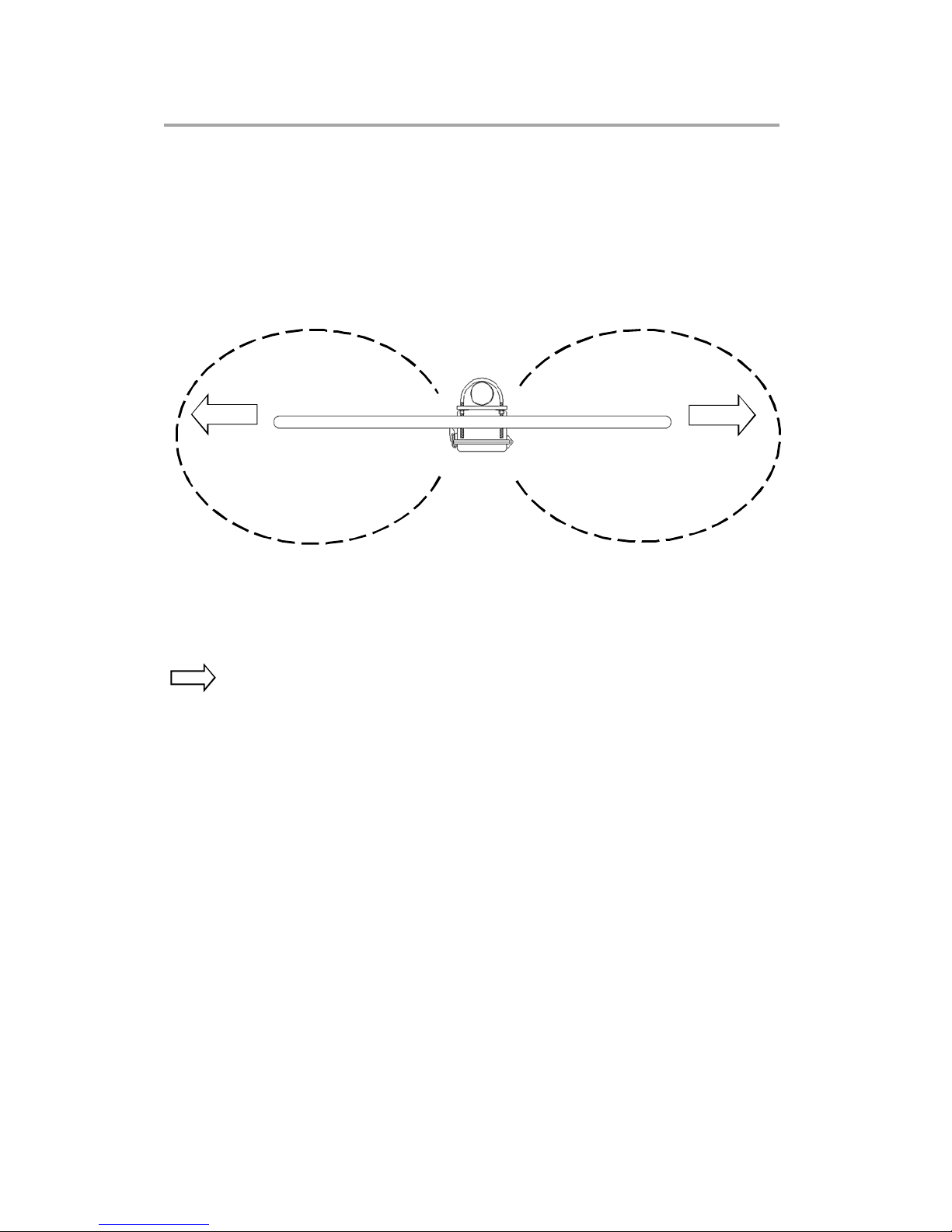
indoor loop antenna. n addition to its exceptional directivity in order to minimize the effects
of local noise, the revolutionary LA800 offers, with its REMOTE TUNING Y TEM, the
perfect solution to keep the antenna away from noise sources by setting it up in quiet areas!
While the control (tuning) box stays at hand’s reach, the WATERPROOF loop element can
be permanently setup outdoors.
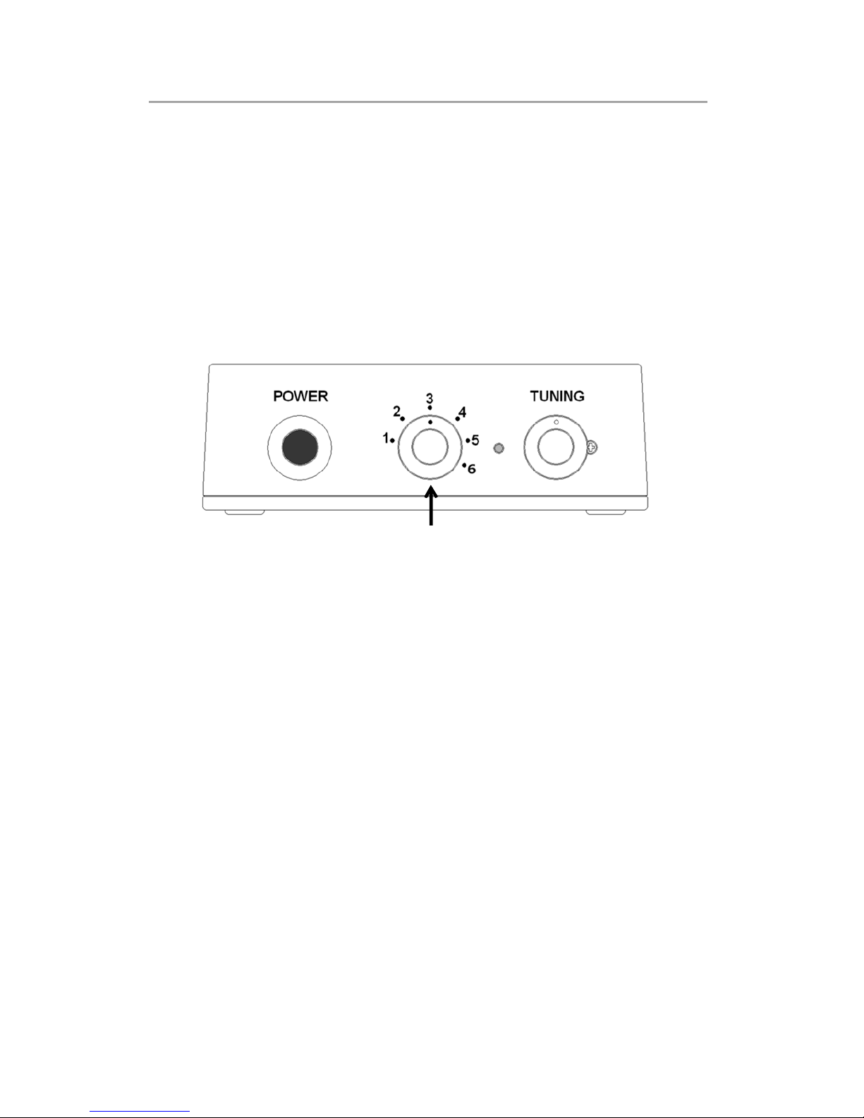
10kHz to 500MHz, 6 position band switch to peak only on the wanted signal. Built-in low
noise amplifier for exceptional 20dB gain. Loop element diameter of 80cm for maximum
reception performance.
Remote tuning – The supplied 10m control and coaxial cables, separating the antenna
from the control box, allow to conveniently operate band switching and fine tuning controls
placed on the control box..
A relay system is used for band switching, providing excellent isolation characteristics.
The relay is efficiently placed inside the loop element, while you can operate it through the
control box via the control cable.
Electronic tuning from 150kHz〜30MHz allows very sharp tuning to the desired
frequency. Shift the aligning point slightly to attenuate unwanted signals while amplifying
the wanted signal.
Waterproof – The loop element’s electronic circuitry is housed in a ABS plastic box, water
and dust proof to P65 standard.
1
2. Included in this package
No.
Description Qty
①
Loop element 1
②
Two U-bolts for mast mount 1
③
Control box 1
④
Control cable (LAN type) 10m 1
⑤
BNC (F)/BNC (F) RG-58U coaxial cable 10m 1
⑥
AC power supply 1
⑦
Printed instruction manual 1
⑧
(for Japanese market only) 1
⑨
Product sticker for the loop element box 1
1
4
3
2
5
6
7 8
9
2
3. Hardware setup
Caution!
LA800 is a RECEIVE ONLY antenna. Do not transmit with it or its circuitry will be severely
damaged, maybe even beyond repair.
As pictured below, mount the LA800 loop element to a (non-supplied) antenna mast, using
the supplied U-bolts.
Antenna masts are typically sold at home centers.
 f you are installing an antenna for the first time, for your own safety as well as
others, seek professional assistance.
 nstallation of this antenna near power lines is dangerous. Do not work on the
system or connect or disconnect cables during periods of lightning activity.
 Do not work on a wet or windy day.
 Do not locate the antenna near overhead power lines or other electric light or
power circuits, or where it can come into contact with such circuits. When
installing the antenna, take extreme care not to come into contact with such
circuits, as they may cause serious injury or death.
SAFETY PRECAUTIONS
Antenna mast
(use 30 to 60mm diameter)
U-bolt
U-bolt
3
For balcony mount, you can also use typical satellite dish balcony mounts, as pictured below.
Such mounts are not supplied by AOR but are usually sold at home-centers.
The loop element’s electronic circuitry is housed in an ABS plastic box, water and dust proof
to P65 standard.
◎ The control and coaxial cables enter the plastic box through two rubber gaskets as
shown below. Connect these to their respective sockets “ANT OUT” and “REMOTE”.
Coaxial cable Control cable
4
◎ Run the coaxial and control cable a bit below and
then back up to the hole into the building, thus
providing a "drip loop" to prevent rain from running
down the cable and into the building
◎ On the receiver side, connect the control cable to the control box and the coaxial
cable directly to your receiver’s antenna socket. Finally, connect the AC power
supply to the control box.
LA
To connect LA800 to an antique receiver with 600Ω antenna terminal, use the optional
MC-600 mpedance Matching Transformer.
LA800 Loop
(outdoors)
Indoors
Receiver’s antenna
input socket
AC power supply
Control box
5
4. Operating instructions
◎ Connect the AC power supply and push the red power button on the control box. A blue
LED will light up.
◎ Tune your receiver to the desired frequency.
◎ Now you need to select one of the 6 available band ranges, using the band switch
numbered from 1 to 6. Refer to the printed switch number / band range information on
the top of the control box.
Please note that position 6 is non-tunable, as the loop is wired to act as an amplified
whip antenna.
◎ Peak the received signal by turning the TUN NG knob slowly to either the left or the right.
The white dot on the tuning know helps you to see the approximate location of the tuning.
For your reference, when the dot is on top as on the above illustration, the tuning PEAK
is approximately in the middle of the selected band.
For example for band switch position 1 (150kHz to 800kHz), it would be roughly peaked
on 475kHz.
Tuning is most critical above 3MHz. For best performance of LA800 and optimal
reception conditions, make sure the selected band is appropriate for the received
frequency, and search for the signal peak with the tuning knob.
◎ A loop antenna is very directional. Reception can be improved by using a third party
antenna mast rotator, and rotate the loop element until your receiver’s signal strength
meter (S-meter) deflects to maximum and the incoming signal sounds clearest. f your
receiver does not have an S-meter, simply adjust for maximum received signal.
Band switch
6
5. Directivity of a loop antenna
A significant advantage of a loop antenna is its directional pattern, a “figure 8” shape with
two null points separated by 180 degrees. The null in reception that is located at right angles
to the plane of the loop can be used for interference reduction. On the other hand, received
signal strength is greatest in the directions indicated by the arrows.
Horizontal radiation pattern of LA800
NULL
NULL
NULL: Angle from which magnitude of the radiation pattern decreases to zero. n other
words, these are the sides from which the antenna receives the least.
Maximum reception performance is achieved when these sides of the loop face the
signal.
7