SAFETY NOTICE – Always disconnect the power supply from the AC outlet when
not in use. If used mobile, it should be noted that the AR-ONE has NOT been
manufactured or tested to meet any specific mobile safety requirements.
The AR-ONE has no internally user adjustable parts.
If using the AR-ONE in a base station situation, the best short wave reception is usually
achieve by the fitting of a separate external earth ro , however, consi er the
implications carefully if your AC buil ing supply uses a Protective Multiple Earth (PME)
system. If in oubt consult an expert electrician. Never earth to a gas pipe!
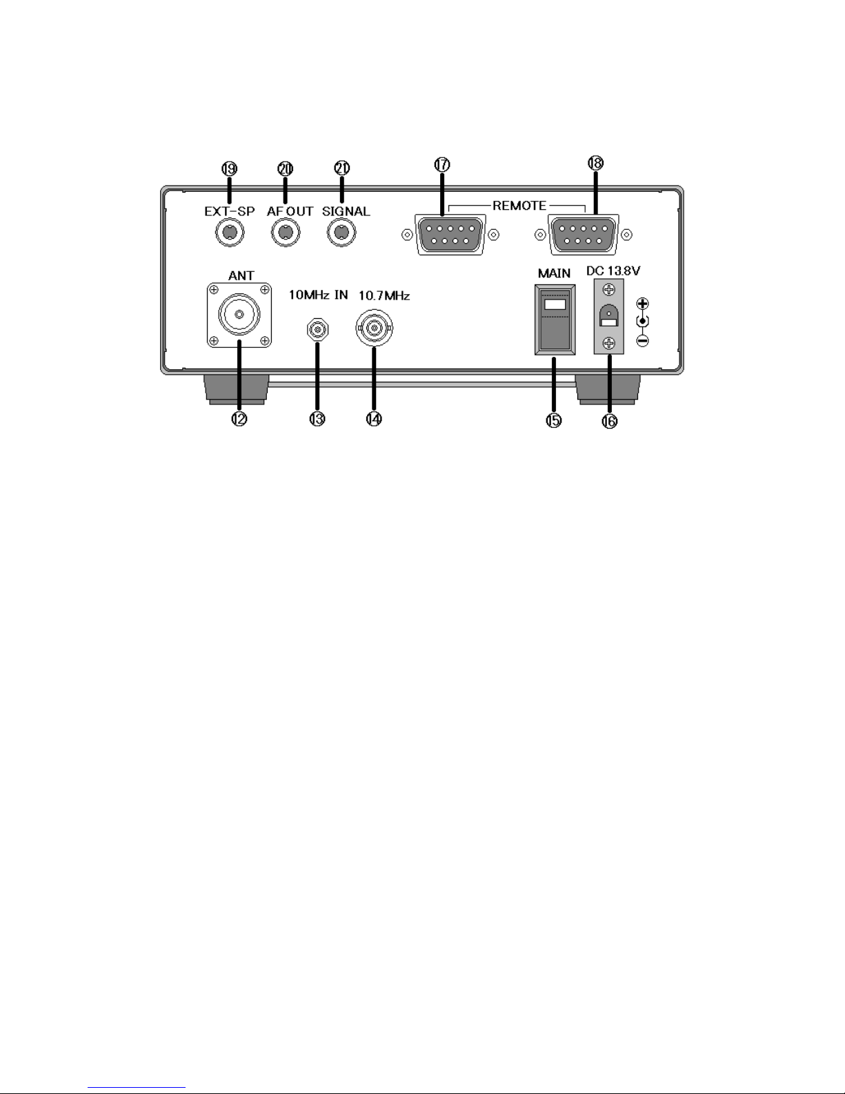
The AR-ONE has a single N type antenna connector for all frequencies. This is inten e
for connection to a 50 Ω (unbalance ) coaxial fe antenna such as a iscone, ipole,
unipole, Yagi, etc. When sighting the antenna, avoi power cables. Ensure that you o
not confuse the antenna an other IF output connectors as they are closely locate .
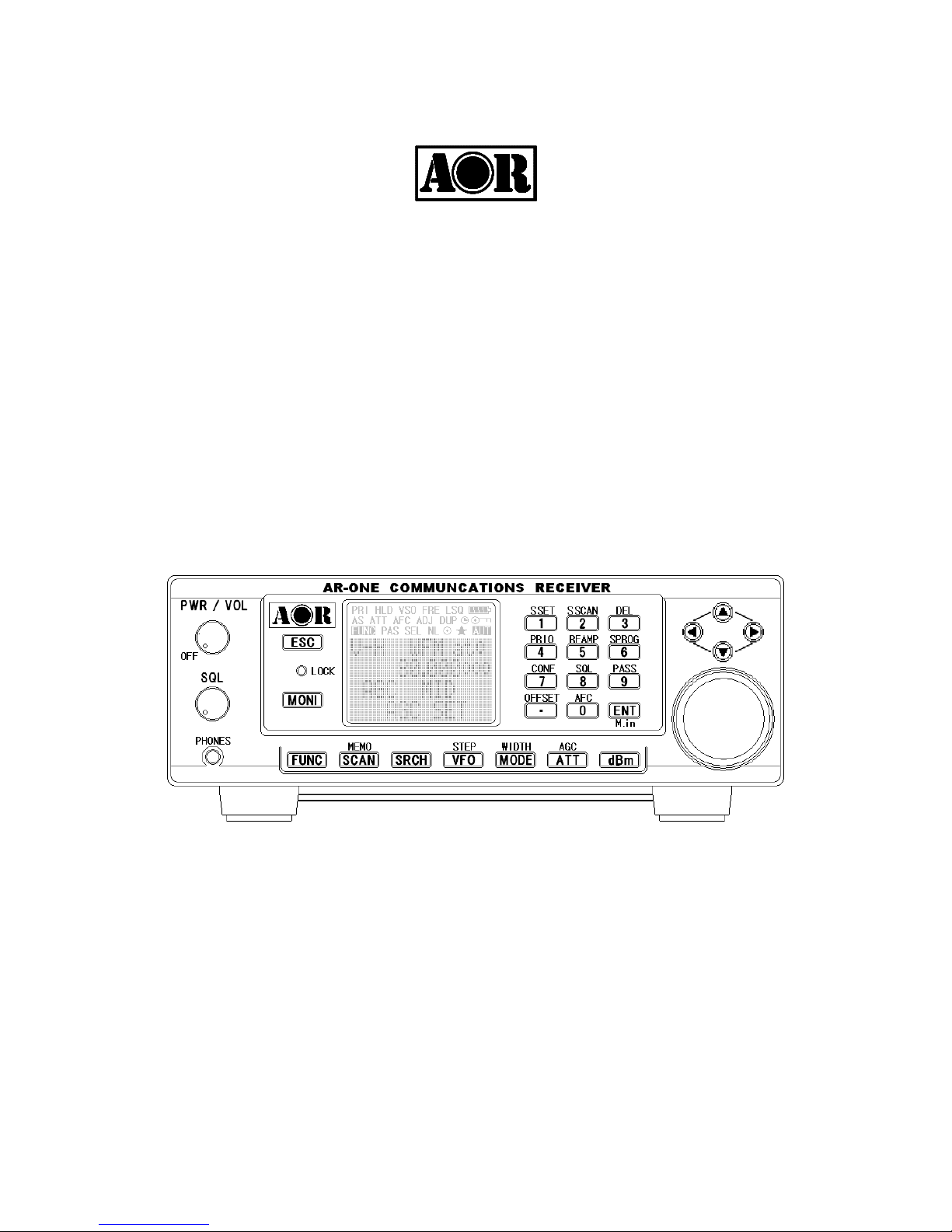
1-3 Attention while operating
1. Certain key operations are acte upon when the key is RELEASED, not while it
is presse . Allow time for the AR-ONE to register such actions before pressing
another key.
2. The key lock (LOCK) is intentionally ma e to be ifficult to operate to prevent
acci ental operation. To release key lock, the LOCK key has to be hel for
more than one secon , the key icon on the LCD confirms operation. The LOCK
is isable uring keying sequences (such as when entering frequencies).
3. If a key sequence is not complete , the microprocessor will automatically abort
most operations after about 90 secon s of keypa inactivity.
4. Currently isplaye VFO ata is save at power own (to increase spee of
operation an to re uce write cycles). For this reason, if the AR-ONE is
powere own using the PWR/VOL control or external power is remove , the
last isplaye frequency will be lost an the frequency use prior to this will be
isplaye when next powere up.
Terminology – Search & Scan
If you have not use a wi e ban receiver before or are not familiar with the terminology
use , it is very important to un erstan the ifference between SEARCH an SCAN mo es.
SEARCH: The AR-ONE provi es several operations where transmissions (active
frequencies) may be automatically locate by sweeping the receiver over a wi e