TESTING 1.0206.07 User manual
Laboratory mortar mixer
1.0206.07
1
Operating Instructions
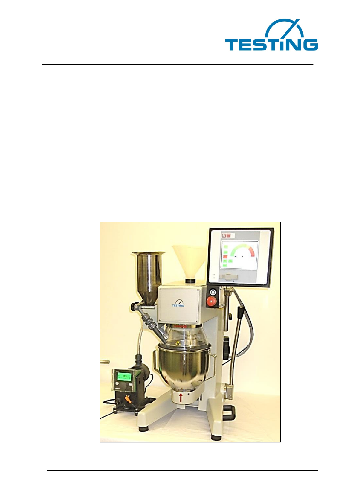
Laboratory mortar mixer
with consistency measurement
Model 1.0206.07

Laboratory mortar mixer
1.0206.07
2
Significance of the operating instructions
Before operating the laboratory mortar mixer, the operating instructions must be read
and understood.
Table of contents Pages
1 Receipt, transport............................................................................................................. 5
1.1
Receipt .........................................................................................................................................5
1.2
Transport......................................................................................................................................5
1.3
Remove the transport packaging .................................................................................................5
1.4
Transport by hand ........................................................................................................................6
2. Scope of delivery.............................................................................................................. 6
3. Basic safety instructions ................................................................................................. 7
3.1
Obligations of the operator...........................................................................................................7
3.2
Requirements for the operating personnel...................................................................................7
3.3
Obligations of the operating personnel ........................................................................................7
3.4
Workplace ....................................................................................................................................7
3.5
Dangers when handling the mortar mixer ....................................................................................8
4. Basic information ............................................................................................................. 8
4.1
Intended use ................................................................................................................................8
4.2
Improper usage ......................................................................................................................... 10
4.3
Information about the CE marking ............................................................................................ 10
4.4
Requirements imposed on the operator.................................................................................... 11
4.5
General safety instructions........................................................................................................ 12
4.6
Protective clothing..................................................................................................................... 13
4.7
Regular checks ......................................................................................................................... 14
5. Description of the mortar mixer..................................................................................... 14
5.1
Mechanical structure ................................................................................................................. 14
5.2
Electrical structure..................................................................................................................... 14
5.3
Safety devices........................................................................................................................... 15
6. Preparations for start-up................................................................................................ 16
6.1
Installation site/environmental conditions ................................................................................. 16
6.2
Electrical connection ................................................................................................................. 16
6.3
Assembly of the sand inlet device............................................................................................. 17
6.4
Check the direction of rotation .................................................................................................. 17
6.5
Change the direction of rotation................................................................................................ 18
6.6
Lower and remove the mixing bowl .......................................................................................... 18
6.7
Loosen and remove the mixer .................................................................................................. 19
6.8
Insert the stirrer and clamp securely......................................................................................... 19
6.9
Insert the mixing bowl and clamp securely ............................................................................... 19
6.10
Bring the mixer bowl into the mixing position............................................................................ 19
6.11
Check the distance between the mixing bowl and the stirrer.................................................... 19
6.12
Set the distance between the mixing bowl and the stirrer ........................................................ 20
7. Technical data................................................................................................................. 20
8. Assembly/installation..................................................................................................... 22
9. Operation ........................................................................................................................ 24
9.1
Switch on the mortar mixer ....................................................................................................... 24
9.2
Starting conditions..................................................................................................................... 24
9.3 Introduction................................................................................................................. 24
9.4 Safety........................................................................................................................... 24
9.5 Special function: Consistency Based Water Demand (CBWD) ............................... 24
9.6 Main components ....................................................................................................... 25

Laboratory mortar mixer
1.0206.07
3
10. Sand specification ...................................................................................................... 26
11. Control unit ................................................................................................................. 27
Start screen ............................................................................................................................................ 27
Manual Mode screen.............................................................................................................................. 27
Window Consistency Based Water Demand (CBWD)........................................................................... 28
Program 1 EN 196 Part 1 and EN 413 Part 2 ....................................................................................... 29
Program 2 EN 480 Part 1...................................................................................................................... 29
Program 3 EN 196 Part 3 and EN 459 Part 2 ....................................................................................... 30
Program 4 EN 196 Part 9...................................................................................................................... 31
Setup screens ........................................................................................................................................ 31
General Setup screen ............................................................................................32
Water Setup screen................................................................................................32
12. Calibration of the mixer for the CBWD measurement .............................................. 33
Adjust the distance between the paddle and the drum .......................................................................... 33
Fine adjustment of the reference value.................................................................................................. 34
13. Calibration of the water metering unit....................................................................... 35
Ventilate the system ............................................................................................................................... 35
Pump settings (DDA30-4) ...................................................................................................................... 35
Pump calibration..................................................................................................................................... 36
200 ml test for the mixer......................................................................................................................... 37
14 Warranty.......................................................................................................................... 38
15. Issue date of the operating instructions ................................................................... 38
16. Copyright..................................................................................................................... 38
17. Address of the manufacturer ..................................................................................... 39
18. Cleaning and maintenance......................................................................................... 39
18.1
Cleaning the mortar mixer......................................................................................................... 39
18.2
Maintenance of the mortar mixer .............................................................................................. 39
18.3
Checking and adjustment.......................................................................................................... 40
18.4
Take the mortar mixer out of operation..................................................................................... 40
18.5
Fault finding............................................................................................................................... 40
19. Spare parts – acquisition and customer service ...................................................... 41
20. Disposal....................................................................................................................... 41

Laboratory mortar mixer
1.0206.07
The notes have the following meaning:
Warning
This warning applies to all procedures that need to be performed with
Danger
This warning applies to all procedures that represent a risk for the
operator if the process cannot be performed with care.
Note
provides practical information about handling the machine
Annexes:
4 pages Graphical representation of the installed programs
1 page Inspection record
Test and measurement report
4
The notes have the following meaning:
This warning applies to all procedures that need to be performed with
care to avoid damage to the device.
This warning applies to all procedures that represent a risk for the
operator if the process cannot be performed with care.
provides practical information about handling the machine
4 pages Graphical representation of the installed programs
Test and measurement report
This warning applies to all procedures that need to be performed with
care to avoid damage to the device.
This warning applies to all procedures that represent a risk for the
operator if the process cannot be performed with care.
provides practical information about handling the machine

Laboratory mortar mixer
1.0206.07
5
1 Receipt, transport
1.1 Receipt
Check the external visible condition of the delivered shipment. If the delivered product is
in good condition, the shipment can then be accepted from the forwarding agent (parcel
service or carrier).
If there is no complaint or transport damage, check the completeness of the shipment
against the delivery note.
If transport damage is detected after receipt, a report with an exact survey of the degree
of damage with a photo must be created immediately. Forward the report to us immedi-
ately by fax. Please do not make any alterations to the delivered shipment.
Using this report, we should be able to assess whether the damage can be fixed
– by the supply of replacement parts
– by sending a specialist for assembly, or only
– by returning the device.
1.2 Transport
The mortar mixer is delivered in suitable cardboard packaging upright on a pallet.
The mortar mixer’s weight is approx. 62 kg.
The mortar mixer can be left in the delivery packaging and transported to its destination
using a forklift or another suitable industrial truck capable of grasping underneath the
pallet.
Ropes or similar lifting gear may only be attached if it has been ensured that no lateral
forces are applied to the packaging and thus possibly to parts of the mortar mixer as
well.
1.3 Remove the transport packaging
To remove the transport packaging, proceed as follows:
•Open the transport packaging’s cover
•Remove the cardboard or Styrofoam transport securing device (inlays)
•Cut open the sidewalls end-to-end at the vertical edges
•Cut off the side walls at the horizontal bottom edges
•Remove the cardboard with the sand inlet
Laboratory mortar mixer
1.0206.07
Danger
The packaging materials (plastics, polystyrene, screws, nails, wood
Warning
Before disposing of the packaging, please check to see whether there
are any further components, instructions, documents or replacement
After you have finished unpacking the device, please make sure that the device has not
been o
bviously damaged during transport. If there are any doubts, please do
nect the device and get in contact with the selling agent.
1.4
Transport by hand
The mortar mixer can be taken to its destination by hand.
Its weight is approx. 62 kg.
The lower
handles affixed on the side in the load centre are used to lift the mortar mixer,
which are designed to lift a load capacity of 40 kg each.
T-
handles mounted on the side in the upper rear area are used to stabilise the load
when carrying.
The mortar mixer
can be picked up by the handles and easily transported to its final l
cation and put down again.
The handles are only used to transport the mortar mixer by hand. They do not serve as
suspension points for transport using hoists.
2.
Scope of delivery
Item Quantity
1. 1
Mortar mixer (including operating instru
tions)
2. 1
Stainless steel mixer
3. 1
Stainless steel bowl
4. 1
Water pump unit
5. 1
LCD display
6. 1
Sand inlet (including 2
screws and the tool)
6
The packaging materials (plastics, polystyrene, screws, nails, wood
etc.) must be kept away from children.
They must be disposed of correctly.
Before disposing of the packaging, please check to see whether there
are any further components, instructions, documents or replacement
parts in the packaging.
After you have finished unpacking the device, please make sure that the device has not
bviously damaged during transport. If there are any doubts, please do
nect the device and get in contact with the selling agent.
Transport by hand
The mortar mixer can be taken to its destination by hand.
handles affixed on the side in the load centre are used to lift the mortar mixer,
which are designed to lift a load capacity of 40 kg each.
handles mounted on the side in the upper rear area are used to stabilise the load
can be picked up by the handles and easily transported to its final l
The handles are only used to transport the mortar mixer by hand. They do not serve as
suspension points for transport using hoists.
Scope of delivery
Designation
Mortar mixer (including operating instru
c-
Stainless steel mixer
Stainless steel bowl
Water pump unit
LCD display
Sand inlet (including 2
hexagon socket
screws and the tool)
The packaging materials (plastics, polystyrene, screws, nails, wood
etc.) must be kept away from children.
They must be disposed of correctly.
Before disposing of the packaging, please check to see whether there
are any further components, instructions, documents or replacement
After you have finished unpacking the device, please make sure that the device has not
bviously damaged during transport. If there are any doubts, please do
not con-
handles affixed on the side in the load centre are used to lift the mortar mixer,
handles mounted on the side in the upper rear area are used to stabilise the load
can be picked up by the handles and easily transported to its final l
o-
The handles are only used to transport the mortar mixer by hand. They do not serve as
Article number
1.0206.07
1.0203.02EN
1.0203.03EN
1.0203-05

Laboratory mortar mixer
1.0206.07
7
3. Basic safety instructions
3.1 Obligations of the operator
The operating instructions must be easily accessible and kept in the immediate vicinity
of the mortar mixer. Only sufficiently qualified operating personnel may work with the
mortar mixer. The operating personnel must be trained before handling the mortar
mixer. Check to see that the operating personnel have read and understood the operat-
ing instructions. Define the exact responsibilities for the operating personnel. Provide
personal protective equipment to all operating personnel.
The person operating the device must ensure that both themselves and other people
are not endangered.
If the operating safety of the mortar mixer is impaired by defects or damage, the mortar
mixer should be taken out of operation immediately and used again only after all of the
sources of danger have been eliminated.
3.2 Requirements for the operating personnel
Only qualified specialist personnel who have been instructed by the operator may work
on the mortar mixer. The minimum age for the operator is 18 years. Individuals under
the age of 18 may only operate the mortar mixer under the supervision of a qualified
skilled worker. The operator is responsible for third parties in the working area.
3.3 Obligations of the operating personnel
The operating personnel must read the operating instructions carefully before handling
the mortar mixer. Please always observe the safety instructions. Wear personal protec-
tive equipment when handling the mortar mixer.
3.4 Workplace
The workplace is located at the control panel in front of the mortar mixer. The workplace
is intended to be used with the connected peripheral equipment provided by the cus-
tomer. Accordingly, the operator must ensure that it is safe. The workplace’s design is
also based on the applicable requirements from the German Health and Safety at Work
Regulations (Betriebs-Sicherheits-Verordnung, BetrSichV) and the analysis of work-
place hazards.

Laboratory mortar mixer
1.0206.07
8
3.5 Dangers when handling the mortar mixer
The mortar mixer is constructed in accordance with the latest technology and accepted
technical rules. However, when it is used, it could lead to dangers for life and limb for
the operator or for a third party, or to impairments or damage to machine technical
components or to other material assets.
The mortar mixer must only be used
•for the intended purpose
•and in a technically faultless safe condition.
Faults that could impair safety must be eliminated immediately.
4. Basic information
4.1 Intended use
This description contains the required information for the intended use of the products
they describe. It is intended for technically qualified personnel. The operator must define
his staff’s area of responsibility precisely.
Qualified personnel are persons who, based on their education, experience, and in-
struction as well as their knowledge of relevant standards, provisions, accident preven-
tion regulations and operating conditions have been authorised by those responsible for
the safety of the machine to execute their respectively required activities and who can
recognise and prevent any possible dangers while doing so
(definition for specialist personnel according to IEC 364).
The specified requirements and limit values as well as safety warnings indicated in
these operating instructions must always be adhered to. Any other use is not consid-
ered to be intended use. If special operation methods or conditions are required, then
advice and permission must be obtained from the manufacturer.
The manufacturer accepts no responsibility for any damages caused due to non-
observance of these ‘safety and operating instructions’.
The mortar mixer is only intended to be used for the mechanical mixing of mortars and
cement pastes for the manufacture of test specimens according to different standards.
The applications below pertain to the intended use:
•MANUAL – operation with selectable mixing speeds
•SAND INLET – for feeding standard sand (1350 g)
•PROGRAM AUTOMATIC – operation, 4 programs according to the stan-
dard

Laboratory mortar mixer
1.0206.07
9
The requirements, threshold values, and safety warnings indicated in these operating
instructions must always be observed.
Note
The mortar mixer is intended for use in dry rooms.
Any other use is not considered to be intended use. If special operation methods or
conditions are required, then advice and permission must be obtained from the manu-
facturer.
Note
The instructions given in these operating instructions are valid only for
the correct usage of the mortar mixer. The operator must observe the
specific standards for the test to carry out operation correctly.
•These operating instructions are intended for dispatchers, fitters, operators,
maintenance technicians and the disposal company.
•Please read these instructions carefully, as they describe how the mortar mixer is
to be operated safely.
•These operating instructions should be considered a part of the product and re-
late only to the mortar mixer with which they were delivered.
•Keep these operating instructions in good order the entire time that the machine
is in operation, so that they can be consulted whenever necessary.
•If the mortar mixer is sold, these operating instructions should be handed over
together with all of the machine’s attachments.
•The manufacturer shall accept no responsibility for any damage that has arisen
from incorrect usage of the device.
•Subject to alterations: The manufacturer reserves the right to make alterations to
the technical descriptions as well as the parts to which these descriptions refer
to, without any prior notice.

Laboratory mortar mixer
1.0206.07
10
4.2 Improper usage
The mortar mixer may only be used in a technically flawless condition.
Use the mortar mixer only for the described applications. Improper usage will void the
warranty.
Manipulations and modifications to the mortar mixer (electrical, mechanical changes,
etc.) that have not been approved in writing by the manufacturer shall be deemed inad-
missible, and the manufacturer shall accept no claims for damages.
We recommend using only original replacement and accessory components; if this is
not the case, then the manufacturer shall accept no liability.
Ensure that no dangerous situations arise during the work. Switch the mortar mixer off
immediately if it is not functioning correctly and inform the manufacturer or the distribu-
tor’s authorised service personnel immediately.
The following usage is deemed improper and thus prohibited:
•Mixing of substances other than those specified under 4.1
•Filling and processing of food
•Overfilling the mixing bowl
•Setting up and operating the mixer in environmental conditions other than those
named under 6.1
4.3 Information about the CE marking
TESTING Bluhm & Feuerherdt GmbH testing equipment carry the CE marking.
The CE marking confirms that the product conforms to the EC Directives that must be
taken into account for the product and that the product complies with the ‘essential re-
quirements’ defined therein and the defined general relevant level of protection. The
conformity-assessment procedure has in each case been carried out in accordance with
the applicable EC Directives. Decisive here is Council Decision 93/465/EEC on the
modules to be used in the technical harmonization directives for the various phases of
the conformity-assessment procedure and the regulations for the affixing and use of the
CE marking.
Laboratory mortar mixer
1.0206.07
11
4.4 Requirements imposed on the operator
The person operating the device must ensure that both themselves and other persons
are not endangered. Only persons who have been instructed on how to operate the de-
vice may operate the device on their own.
If the operating safety of the device is impaired by defects or damage, it must be taken
out of operation immediately and used again only after all sources of danger have been
eliminated.
Check to see whether the specification given on the identification plate corresponds with
your mains voltage. Connect only to alternating current.
If the device or the power supply line is damaged, remove the mains plug immediately.
Danger
Take all necessary safety precautions during mixing to prevent dust
from getting into the eyes, mouth and nose when stirring.
•The usage, lifting, installation, maintenance and scrapping of the mortar mixer
should only be carried out by qualified personnel. Qualified personnel are persons
who, as a result of their experience and knowledge in relation to the operation of the
mortar mixer and the regulations, guidelines and its handling, are authorised to work
with the machine. The operator must be thoroughly trained in relation to the opera-
tion of the machine and the safety devices that the machine is equipped with so that
incorrect usage is prevented. Safety devices must always be installed and checked
daily.
•Manipulations and modification to the machine (electrical and mechanical altera-
tions, etc.) that have not been authorised with the written agreement of the manufac-
turer shall be considered to be forbidden and the manufacturer shall accept no
claims for damages.
•Ensure that no dangerous situations arise during the work. Switch the machine off
immediately if it is not functioning correctly and inform the manufacturer or the dis-
tributor’s authorised service personnel immediately.
•Do not place any wires or tools in the existing openings.

Laboratory mortar mixer
1.0206.07
4.5 General safet
y instructions
Warning
All of the instructions must be read. Failure to comply with the instru
tions that are described below could cause electric shocks, fires
1) The workplace
•
Keep your working area clean and tidy.
lead to accidents.
•
Do not work with the mortar mixer in potentially explosive environments in which
flammable liquids, gasses or dusts are present. Power tools create sparks that
could ignite dust or vapours.
•Keep chi
ldren and other persons away from the device while it is in use. You
could lose control over the device if you are distracted.
2) Electrical safety
•
The connecting plug of the mortar mixer (CEE/ 16A) must fit into the correspon
ing socket. The plug must no
plugs together with the protected earthed devices. Unaltered plugs and correctly
fitting sockets will reduce the risk of an electric shock.
•
Avoid any body contact with earthed surfaces such as pipes, heating
stoves and refrigerators. There is a higher risk of electric shock when your body
is earthed.
•
Keep the device away from rain or moisture. Water penetrating into the electric
device will increase the risk of an electric shock.
•
Do not misuse or misa
device up or use it to pull the plug out of the socket. Keep the cable away from
heat, oil, sharp edges and moving machinery parts. Damaged or tangled cables
increase the risk of an electric shock
3) The safety of personnel
•
Be attentive and pay attention to what you are doing and work with prudence
when at work. Do not use the device when you are tired or if you are under the
influence of drugs, alcohol or medication. One moment of carelessness w
ing the device can lead to serious injuries.
•
Wear personal protective equipment and always wear protective googles. Wea
ing personal protective equipment such as dust masks and non
will reduce the risk of injuries.
•Remove any instal
lation tools or spanners before switching the mortar mixer on.
A tool or spanner that is located in a part of the device that rotates could lead to
injuries.
12
y instructions
All of the instructions must be read. Failure to comply with the instru
tions that are described below could cause electric shocks, fires
and/or serious injuries.
Keep your working area clean and tidy.
Disorder and unlit working areas could
Do not work with the mortar mixer in potentially explosive environments in which
flammable liquids, gasses or dusts are present. Power tools create sparks that
could ignite dust or vapours.
ldren and other persons away from the device while it is in use. You
could lose control over the device if you are distracted.
The connecting plug of the mortar mixer (CEE/ 16A) must fit into the correspon
ing socket. The plug must no
t be altered in any way. Do not use any adapter
plugs together with the protected earthed devices. Unaltered plugs and correctly
fitting sockets will reduce the risk of an electric shock.
Avoid any body contact with earthed surfaces such as pipes, heating
stoves and refrigerators. There is a higher risk of electric shock when your body
Keep the device away from rain or moisture. Water penetrating into the electric
device will increase the risk of an electric shock.
Do not misuse or misa
ppropriate the cable in order to carry the device, hang the
device up or use it to pull the plug out of the socket. Keep the cable away from
heat, oil, sharp edges and moving machinery parts. Damaged or tangled cables
increase the risk of an electric shock
.
Be attentive and pay attention to what you are doing and work with prudence
when at work. Do not use the device when you are tired or if you are under the
influence of drugs, alcohol or medication. One moment of carelessness w
ing the device can lead to serious injuries.
Wear personal protective equipment and always wear protective googles. Wea
ing personal protective equipment such as dust masks and non
will reduce the risk of injuries.
lation tools or spanners before switching the mortar mixer on.
A tool or spanner that is located in a part of the device that rotates could lead to
All of the instructions must be read. Failure to comply with the instru
c-
tions that are described below could cause electric shocks, fires
Disorder and unlit working areas could
Do not work with the mortar mixer in potentially explosive environments in which
flammable liquids, gasses or dusts are present. Power tools create sparks that
ldren and other persons away from the device while it is in use. You
The connecting plug of the mortar mixer (CEE/ 16A) must fit into the correspon
d-
t be altered in any way. Do not use any adapter
plugs together with the protected earthed devices. Unaltered plugs and correctly
Avoid any body contact with earthed surfaces such as pipes, heating
systems,
stoves and refrigerators. There is a higher risk of electric shock when your body
Keep the device away from rain or moisture. Water penetrating into the electric
ppropriate the cable in order to carry the device, hang the
device up or use it to pull the plug out of the socket. Keep the cable away from
heat, oil, sharp edges and moving machinery parts. Damaged or tangled cables
Be attentive and pay attention to what you are doing and work with prudence
when at work. Do not use the device when you are tired or if you are under the
influence of drugs, alcohol or medication. One moment of carelessness w
hen us-
Wear personal protective equipment and always wear protective googles. Wea
r-
ing personal protective equipment such as dust masks and non
-slip safety boots
lation tools or spanners before switching the mortar mixer on.
A tool or spanner that is located in a part of the device that rotates could lead to

Laboratory mortar mixer
1.0206.07
13
•Wear suitable clothing. Do not wear any baggy clothing or jewellery. Keep all
hair, clothing and gloves away from moving parts. Loose clothing, jewellery or
long hair could become tangled in moving parts.
4) Careful handling and usage of power tools
•Remove the mains plug from the socket before carrying out any device settings
or changing accessory parts. These precautionary measures will prevent the de-
vice from being started unintentionally.
•Store unused power tools out of the reach of children. Do not allow persons to
use the device who are not familiar with it or who have not read these instruc-
tions. Power tools are dangerous when they are used by inexperienced persons.
•Take careful care of the device. Check to see that moving parts of the device
function correctly and do not jam, whether there are any parts that are broken, or
are so badly damaged that the functioning of the device is impaired. Ensure that
damaged parts are repaired before the device is used. Many accidents are
caused by poorly maintained machines.
•Use power tools, accessories, insertion tools and so on in accordance with these
instructions and in the manner that is prescribed for these special types of de-
vices. Take account of the working conditions and the activity that is to be carried
out. Using power tools for applications for which they were not intended can lead
to dangerous situations.
5) Service
•Allow your device to be repaired only by qualified specialist personnel and only
with original replacement parts. This will ensure that the device will remain safe.
4.6 Protective clothing
The operator must ensure that all personnel wear the appropriate protective clothing, for
example:
•safety boots
•suitable outer clothing
•protective gloves
•a face mask
•respiratory protection

Laboratory mortar mixer
1.0206.07
14
4.7 Regular checks
The mortar mixer must be checked for industrial safety at regular intervals. There are
national regulations for this, which must be observed.
5. Description of the mortar mixer
5.1 Mechanical structure
The mortar mixer’s housing consists of a stable light metal casting.
The stirrer is made of stainless steel and is connected with the planetary gear by a
quick release fastener. It rotates on its own axis and is moved by an electric motor in a
planetary motion around the bowl axis at 2 fixed speeds.
The mixing bowl is made of NIROSTA steel and can be removed from the working posi-
tion after lowering.
The contours of the stirrer and mixing bowl match and guarantee a distance of 3.0 ± 1.0
mm between the mixing bowl and the stirrer.
This distance can be adjusted by loosening two clamping screws.
The electromechanical sand inlet is made of sheet steel. In the sand inlet’s housing
there is an electromagnet which moves the striker plate via a connecting rod. The striker
plate is kept shut by a spring and can be opened if the machine is switched off or oper-
ated at low speed.
5.2 Electrical structure
The supply voltage for the mixer must be 3 x 230 V + N + PE, 50 Hz.
The power is supplied by a 5-pin connector according to the CEE standard (the direc-
tion of rotation can be altered without opening the connector housing - see point 6.4).
The main switch, which disconnects the supply voltage of the mixer from all phases, is
situated on the mortar mixer’s right head side as seen from the front.
1) Components in the mortar mixer’s rear area
•I/O circuit board (on a fold-out assembly frame)
After folding out the assembly frame, the connecting terminals of the power supply ca-
ble and the fuses to protect the mixer against short circuiting are accessible.
2) Components in the mortar mixer’s head room
•Connecting terminals for the 3-pin main switch

Laboratory mortar mixer
1.0206.07
15
3) Display and control unit for the mortar mixer
•16 bit CPU, Hitachi H8 2646, 16 byte internal flash memory, 1 Kbyte RAM
•Display
•Multi-coloured signal lamps to indicate operational readiness
•8 function buttons
•Buzzer
•Unlockable emergency stop button
•Programming interface
The display and control unit is connected to the I/O board on the fold-out assembly
frame by a double-sided, pluggable, shielded control cable.
5.3 Safety devices
The mortar mixer is equipped with the following safety devices:
1. EMERGENCY STOP switch
The drive motor is disconnected from the mains power supply by the 3-pin safety
module when the EMERGENCY STOP switch is pressed.
To reactivate the control system, the EMERGENCY STOP switch must be
brought back to its home position again by rotating the switch in the direction of
the arrow.
2. Inductive, electronic proximity switch
The proximity switch in the mixing bowl mounting is energised by the mixing
bowl’s bottom flange and monitors its correct fit in the mounting.
If the mixing bowl is not inserted into the mounting, the safety module prevents
the mortar mixer from being operated. Acknowledgement via the display and con-
trol unit.
3. Inductive, electronic proximity switch
The proximity switch in the mixing bowl lifting device is energised on reaching the
mixing position and monitors the adherence to the correct mixing position.
If the mixing bowl is not in the mixing position, the safety module prevents the
mortar mixer from being operated. Acknowledgement via the display and control
unit.
4. Fixed protective cover
The mixing bowl is covered in the mixing position by a fixed protective cover
which encloses the stirrer on all sides.

Laboratory mortar mixer
1.0206.07
6.
Preparations for start
6.1
Installation site/environmental conditions
Warning
The following limit values apply in this regard:
Ambient temperature
DIN EN 60204-
1, 4.4.2
Air humidity
DIN EN 60204-
1, 4.4.3
Note
Install the
6.2
Electrical connection
A CEE 16A
power supply connection box
for the mortar mixer’s power supply connection.
Plug the mortar mixer’s 5-
wire cable with the CEE
nection box.
16
Preparations for start
-up
Installation site/environmental conditions
The operation of the mortar mixer is
permitted only in dry rooms!
The following limit values apply in this regard:
1, 4.4.2
+5°C to +40°C
1, 4.4.3
30% to 95%
Install the
mortar mixer on a load-
bearing, level base.
Electrical connection
power supply connection box
400 Volt 3Ph+1N+1PE, 50 Hz
for the mortar mixer’s power supply connection.
wire cable with the CEE
plug (16A) in this power supply co
The operation of the mortar mixer is
bearing, level base.
400 Volt 3Ph+1N+1PE, 50 Hz
must be used
plug (16A) in this power supply co
n-
Laboratory mortar mixer
1.0206.07
6.3
Assembly of the sand inlet device
The sand inlet device for standard sand is assembled with 2 hexagon socket screws
M6, as seen from the front on the left side of the mortar mixer above the mixing bow
The electrical connection between the sand inlet device and the mortar mixer is esta
lished by a 3-
pin connector also mounted on the left side of the mixer. The sand inlet
device is ready for operation after establishing the electrical connection and lo
6.4
Check the direction of rotation
Warning
The direction of rotation must be checked as described below to pr
Process for checking the direction of rotation
1.
Establish a connection between the mortar
inserting the 5-
pin CEE mains plug into the corresponding socket.
2.
Unlock the EMERGENCY STOP switch by turning it in a clockwise direction.
3.
Bring the main switch into position ‘
4.
Insert the stirrer and clamp
5.
Insert the mixer bowl into the bowl holder and clamp securely (see point 6.8).
6.
Bring the mixer bowl into the mixing position (see point 6.9).
7.
Press the F6 button on the operating module for the mixing speed ‘
8. Set th
e gear head’s direction of rotation.
9.
Stop the mortar mixer by pressing the F6 button on the operating module.
10.
Bring the main switch into position ‘
11.
Pull out the CEE mains plug from the socket.
Warning
The mixing head must rotate in the direction of the indicated arrow (in
17
Assembly of the sand inlet device
The sand inlet device for standard sand is assembled with 2 hexagon socket screws
M6, as seen from the front on the left side of the mortar mixer above the mixing bow
The electrical connection between the sand inlet device and the mortar mixer is esta
pin connector also mounted on the left side of the mixer. The sand inlet
device is ready for operation after establishing the electrical connection and lo
Check the direction of rotation
The direction of rotation must be checked as described below to pr
vent damage to the mortar mixer.
Process for checking the direction of rotation
Establish a connection between the mortar
mixer and the mains power supply by
pin CEE mains plug into the corresponding socket.
Unlock the EMERGENCY STOP switch by turning it in a clockwise direction.
Bring the main switch into position ‘
-I-’ or ‘-ON-’.
Insert the stirrer and clamp
securely (see point 6.7).
Insert the mixer bowl into the bowl holder and clamp securely (see point 6.8).
Bring the mixer bowl into the mixing position (see point 6.9).
Press the F6 button on the operating module for the mixing speed ‘
e gear head’s direction of rotation.
Stop the mortar mixer by pressing the F6 button on the operating module.
Bring the main switch into position ‘
-O-’ or ‘-OFF’.
Pull out the CEE mains plug from the socket.
The mixing head must rotate in the direction of the indicated arrow (in
an anti-
clockwise direction), whereby the mixer
performs a movement in the opposite direction!
The sand inlet device for standard sand is assembled with 2 hexagon socket screws
M6, as seen from the front on the left side of the mortar mixer above the mixing bow
l.
The electrical connection between the sand inlet device and the mortar mixer is esta
b-
pin connector also mounted on the left side of the mixer. The sand inlet
device is ready for operation after establishing the electrical connection and lo
cking.
The direction of rotation must be checked as described below to pr
e-
vent damage to the mortar mixer.
mixer and the mains power supply by
pin CEE mains plug into the corresponding socket.
Unlock the EMERGENCY STOP switch by turning it in a clockwise direction.
Insert the mixer bowl into the bowl holder and clamp securely (see point 6.8).
Press the F6 button on the operating module for the mixing speed ‘
-62/140 rpm-’.
Stop the mortar mixer by pressing the F6 button on the operating module.
The mixing head must rotate in the direction of the indicated arrow (in
clockwise direction), whereby the mixer
performs a movement in the opposite direction!

Laboratory mortar mixer
1.0206.07
If the mixer head rotates
in the direction of the arrow
the mortar mixer is ready for operation.
If the mixer head rotates
in the opposite direction to the arrow
tion), the mortar mixer’s direction of rotation must be changed (see point 6.4).
6.5 Change
the direction of rotation
The direction of rotation can be altered wit
out opening the connector housing.
After the mains connection plug has been r
moved from the socket, the phases on the
contact side of the plug can be changed with
an appropriate s
crewdriver.
To perform this, the screwdriver must be i
serted into the slit provided on the contact
side of the plug and rotated by 180°.
Warning
Work on electrical equipment must only be carried out by specialist
6.6
Lower and remove the mixing bowl
Disengage the hand lever on the right side of the mortar mixer by pushing it right and
swivelling it forwards as far as it will go. The mixing bowl is lowered.
The container carrier is in the lowered position. Rotate
in an anti-
clockwise direction until the two arrows fixed to the mixing pot and the co
tainer carrier are vertically aligned. Lift the mixing pot upwards and slightly forward at an
angle until the eccentric clamp is no long
pot backwards and remove.
18
in the direction of the arrow
(in an anti-
clockwise direction),
the mortar mixer is ready for operation.
in the opposite direction to the arrow
(in a clockwise dire
tion), the mortar mixer’s direction of rotation must be changed (see point 6.4).
the direction of rotation
The direction of rotation can be altered wit
h-
out opening the connector housing.
After the mains connection plug has been r
e-
moved from the socket, the phases on the
contact side of the plug can be changed with
crewdriver.
To perform this, the screwdriver must be i
n-
serted into the slit provided on the contact
side of the plug and rotated by 180°.
Safety notice!
Work on electrical equipment must only be carried out by specialist
personnel!
Lower and remove the mixing bowl
Disengage the hand lever on the right side of the mortar mixer by pushing it right and
swivelling it forwards as far as it will go. The mixing bowl is lowered.
The container carrier is in the lowered position. Rotate
the mixing pot using the handles
clockwise direction until the two arrows fixed to the mixing pot and the co
tainer carrier are vertically aligned. Lift the mixing pot upwards and slightly forward at an
angle until the eccentric clamp is no long
er in the container carrier. Now tilt the mixing
pot backwards and remove.
clockwise direction),
(in a clockwise dire
c-
tion), the mortar mixer’s direction of rotation must be changed (see point 6.4).
Work on electrical equipment must only be carried out by specialist
Disengage the hand lever on the right side of the mortar mixer by pushing it right and
the mixing pot using the handles
clockwise direction until the two arrows fixed to the mixing pot and the co
n-
tainer carrier are vertically aligned. Lift the mixing pot upwards and slightly forward at an
er in the container carrier. Now tilt the mixing

Laboratory mortar mixer
1.0206.07
19
6.7 Loosen and remove the mixer
Firmly grasp the mixer with the left hand and the mixer mounting’s knurled ring with the
right hand.
Loosen the knurled ring in an anti-clockwise direction until it can be shifted upwards.
Now pull out the stirrer in a downward direction.
6.8 Insert the stirrer and clamp securely
Insert the stirrer in the agitator head’s quick-action clamping release fastener with a
slight rotary movement until you feel it reach the end stop. Hold the stirrer with the left
hand and rotate the knurled ring until it falls downwards by approximately 10 mm. Now
clamp the knurled ring securely with the right hand by rotating it in a clockwise direction.
6.9 Insert the mixing bowl and clamp securely
The container carrier is in the lowered position. Grasp the mixing pot by the side han-
dles to insert it. The red arrow must point to the front. The mixing pot must now be in-
serted in such a way that both arrows attached to the mixing pot and the container car-
rier are aligned. Now tilt it slightly forward and let the mixing pot slide in effortlessly. The
mixing pot is tightened in a clockwise direction to lock.
6.10 Bring the mixer bowl into the mixing position
First swivel the hand lever to the right and then backwards as far as it will go and en-
gage it to the left.
The mixing bowl is locked into place in the mixing position.
6.11 Check the distance between the mixing bowl and the stirrer
Lower the mixing bowl and remove (see point 6.5), then loosen the stirrer and remove
(see point 6.6). The protective guard can now be removed from below by unscrewing
the 3 hexagon socket screws on the protective guard’s flange. Now reinsert the stirrer
and clamp securely (see point 6.7), also insert the mixing bowl and clamp securely (see
point 6.8), afterwards bring the mixer bowl into the mixing position (see point 6.9). With
the distance gauge (TESTING art. No.: 1.0203.07) the distance can be checked (EN
196-T1 3 ± 1 mm) and adjusted as described in point 6.11. If the distance conforms to
the standards, the protective guard is reassembled.
Laboratory mortar mixer
1.0206.07
20
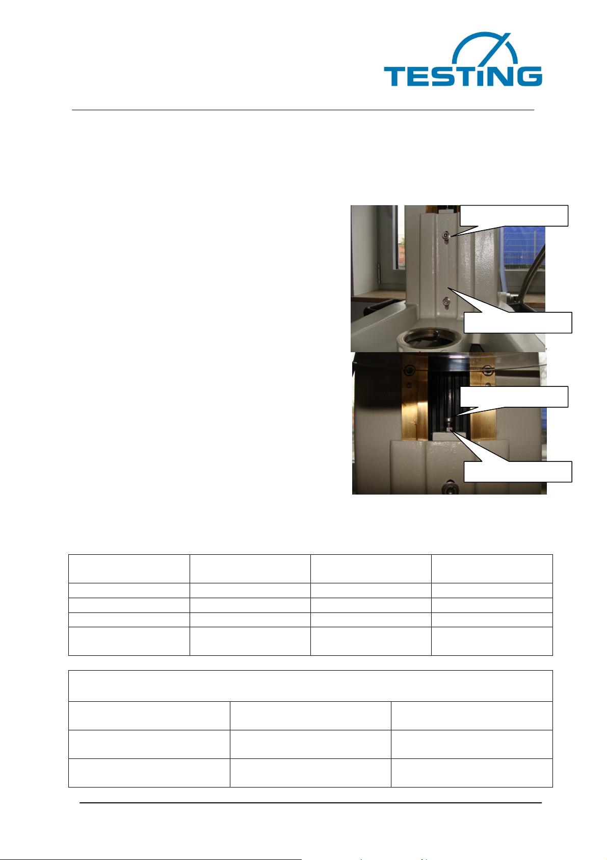
6.12 Set the distance between the mixing bowl and the stirrer
If the distance between the mixing bowl and the stirrer is greater than the applicable
standard allows for, this can be adjusted. The mixing bowl must first be lowered and
removed (see point 6.5). The two clamping
screws can now be loosened on the holder for
the mixing bowl by approximately 1 revolution.
Now loosen the lock nut of the adjusting screw at
the upper end of the mixing bowl holder, and
then set the distance with the help of the adjust-
ing screw from the mixing bowl mounting and
check with the distance gauge.
•By turning the adjusting screw in a clock-
wise direction, the distance is reduced.
•By turning the adjusting screw in an anti-
clockwise direction, the distance is in-
creased.
If the distance is set correctly, the lock nut, the
adjusting screw and both of the clamping screws
on the holder for the mixing bowl must be tight-
ened. The protective guard must be reassembled,
the mixing bowl and the stirrer must then be in-
serted.
7. Technical data
Footprint approx.
300 x 550 mm
Power consumption 0.20/0.37 kW
Installation height approx. 500 mm Alternating current 400 V
Weight approx. 62 kg Frequency 50 Hz
Number of phases 3
Fine wire fuse time-
lag
5 x 20 mm/250 V/2.5
A
Mortar mixer speeds (rpm) according to DIN EN 196-1
Rotation
(min
-1
)
Planetary motion
(min
-1
)
Low
speed 140 ± 5 62 ± 5
High
speed 285 ± 10 125 ± 10
Clamping screw
Clamping screw
Lock nut
Adjusting screw
Table of contents
Other TESTING Laboratory Equipment manuals


Popular Laboratory Equipment manuals by other brands


Agilent Technologies
Agilent Technologies 7200 Troubleshooting and maintenance guide

Molecular Devices
Molecular Devices QPix 420 Pre-installation guide

enviromental express
enviromental express AutoBlock Fill Operation & instruction manual

CMA Dishmachines
CMA Dishmachines VINCILAB 2 quick start guide

Novus
Novus NV-100PS user manual

Keysight
Keysight 81950A Getting started guide