Parker BA-DME012-E User manual

Breathing Air Purifier
BA-DME012 - BA-DME080
Original Language
User Guide
Benutzerhandbuch / Guide de l'utilisateur / Guía del usuario / Guida per l'utente
Instrukcja uzytkownika / Uživatelská prírucka
aerospace
climate control
electromechanical
filtration
fluid & gas handling
hydraulics
pneumatics
process control
sealing & shielding
EN
DE
FR
ES
IT
PL
CS


CONTENTS
1 Safety Information ........................................................................................................................................................................................1
1.1 Markings and Symbols ........................................................................................................................................................................2
2 Technical Specification................................................................................................................................................................................3
2.1 Technical Data ......................................................................................................................................................................................3
2.2 Approvals Compliance and Exemptions............................................................................................................................................4
2.3 Materials of Construction ....................................................................................................................................................................5
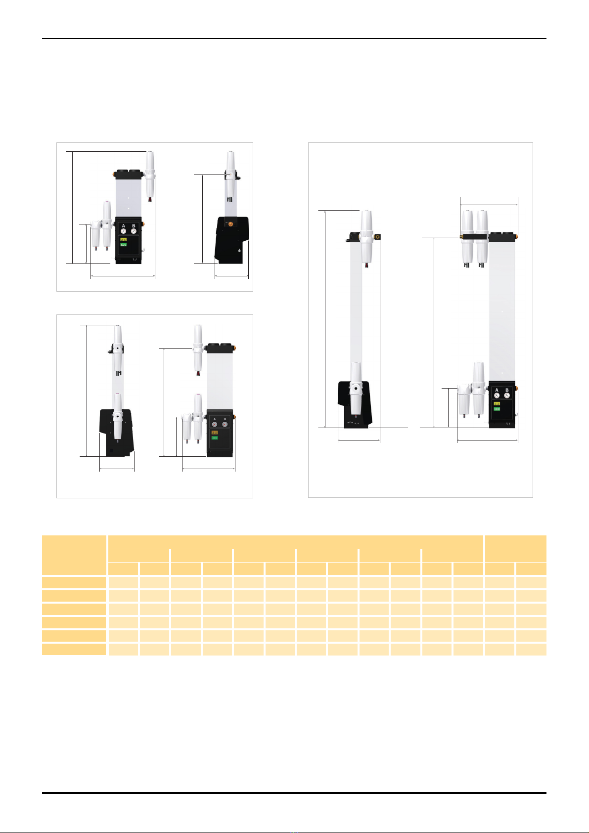
2.4 Dimensions ...........................................................................................................................................................................................6
3.1 Receiving and Inspecting the Equipment ..........................................................................................................................................8
3.1.1 Storage.........................................................................................................................................................................................8
3.1.2 Unpacking ....................................................................................................................................................................................8
3.1.3 Lifting and Handling......................................................................................................................................................................8
3.2 Overview of the Equipment .................................................................................................................................................................8
4 Installation and Commissioning..................................................................................................................................................................9
4.1 General ..................................................................................................................................................................................................9
4.1.1 Locating the Equipment................................................................................................................................................................9
4.1.2 Space Requirements....................................................................................................................................................................9
4.2 Mechanical Installation ........................................................................................................................................................................9
4.2.1 General Requirements .................................................................................................................................................................9
4.2.2 Securing the Dryer .......................................................................................................................................................................9
4.2.3 Piping Connections ......................................................................................................................................................................9
4.2.4 Purge Air Flow..............................................................................................................................................................................9
4.3 Electrical connections .......................................................................................................................................................................10
4.3.1 Connecting the electrical Supply............................................................................................................................................10
4.3.2 Auxiliary Connections.................................................................................................................................................................10
4.4 Initial Start Up .....................................................................................................................................................................................12
4.4.1 Getting Started ...........................................................................................................................................................................12
4.4.2 Start-Up ......................................................................................................................................................................................12
5 Operation.....................................................................................................................................................................................................13
5.1 Normal Operation ...............................................................................................................................................................................13
5.2 Dewpoint Dependent Switching (DDS).............................................................................................................................................13
5.3 Power Indicator and Fault Indicator Operation ...............................................................................................................................14
5.4 Shut-down ...........................................................................................................................................................................................14
6 Preventative Maintenance..........................................................................................................................................................................15
6.1 Service Intervals ................................................................................................................................................................................15
6.2 Preventative Maintenance Kits..........................................................................................................................................................16
8 Troubleshooting..........................................................................................................................................................................................19


1
1 Safety Information
Do not operate this equipment until the safety information and instructions in this user guide have been read and understood by all
personnel concerned.
USER RESPONSIBILITY
FAILURE OR IMPROPER SELECTION OR IMPROPER USE OF THE PRODUCTS DESCRIBED HEREIN OR RELATED ITEMS CAN CAUSE
DEATH, PERSONAL INJURY AND PROPERTY DAMAGE.
This document and other information from Parker Hannifin Corporation, its subsidiaries and authorised distributors provide product or system
options for further investigation by users having technical expertise.
The user, through its own analysis and testing, is solely responsible for making the final selection of the system and components and assuring
that all performance, endurance, maintenance, safety and warning requirements of the application are met. The user must analyse all aspects of
the application, follow applicable industry standards, and follow the information concerning the product in the current product catalogue and in
any other materials provided from Parker or its subsidiaries or authorised distributors.
To the extent that Parker or its subsidiaries or authorised distributors provide component or system options based upon data or specifications
provided by the user, the user is responsible for determining that such data and specifications are suitable and sufficient for all applications and
reasonably foreseeable uses of the components or systems.
Only competent personnel trained, qualified, and approved by Parker Hannifin should perform installation, commissioning, service and repair
procedures.
Use of the equipment in a manner not specified within this user guide may result in an unplanned release of pressure, which may cause serious
personal injury or damage.
When handling, installing or operating this equipment, personnel must employ safe engineering practices and observe all related regulations,
health & safety procedures, and legal requirements for safety.
Ensure that the equipment is depressurised and electrically isolated, prior to carrying out any of the scheduled maintenance instructions specified
within this user guide.
Parker Hannifin can not anticipate every possible circumstance which may represent a potential hazard. The warnings in this manual cover the
most known potential hazards, but by definition can not be all-inclusive. If the user employs an operating procedure, item of equipment or a
method of working which is not specifically recommended by Parker Hannifin the user must ensure that the equipment will not be damaged or
become hazardous to persons or property.
Most accidents that occur during the operation and maintenance of machinery are the result of failure to observe basic safety rules and
procedures. Accidents can be avoided by recognising that any machinery is potentially hazardous.
Should you require an extended warranty, tailored service contracts or training on this equipment, or any other equipment within the Parker
Hannifin range, please contact your local Parker Hannifin office.
Details of your nearest Parker Hannifin sales office can be found at www.parker.com/dhfns
Retain this user guide for future reference.

2
1.1 Markings and Symbols
The following markings and international symbols are used on the equipment or within this manual:
Caution, Read the User Guide. Wear ear protection
Risk of electric shock. Pressurised components on the system
Highlights actions or procedures which, if not performed
correctly, may lead to personal injury or death. Remote control. The dryer may start automatically without
warning.
Highlights actions or procedures which, if not performed
correctly, may lead to damage to this product. Conformité Européenne
Highlights actions or procedures which, if not performed
correctly, could lead to electric shock. When disposing of old parts always follow local waste
disposal regulations.
Read the User Guide Waste electrical and electronic equipment should not be
disposed of with municipal waste.
Use a fork lift truck to move the dryer.

3
2 Technical Specification
2.1 Technical Data
Flow Data
Stated flows are for operation at 7 bar g (100 psi g / 0.7 MPa g) with reference to 20ºC, 1 bar a, 0% relative water vapour pressure.
Performance
Operating Data
Electrical Data
Model Pipe Size Flowrate
Inlet Outlet L/s m3/min m3/hr cfm
BA-DME012-E G 1/2 G 3/8 11 0.68 41 24
BA-DME015-E G 1/2 G 3/4 15 0.91 55 32
BA-DME020-E G 1/2 G 3/4 19 1.19 71 42
BA-DME025-E G 1/2 G 3/4 25 1.50 90 53
BA-DME030-E G 1/2 G 3/4 31 1.84 110 65
BA-DME040-E G 3/4 G 3/4 40 2.49 149 88
BA-DME050-E G 1 G 1 50 3.01 180 106
BA-DME060-E G 1 G 1 61 3.69 221 130
BA-DME080-E G 1 G 1 83 4.99 299 176
Dryer Model
Pressure Dewpoint
(Standard)
ISO 8573-1:2010
Water Classification
oCoF(Standard)
BA-DME012 - 080 -40 -40 Class 2 (1)
(1) ISO 8573-1 classifications apply when the dryer is installed with the filtration supplied
Model
Min Operating
Pressure
Max Operating
Pressure
Min Operating
Temperature
Max Operating
Temperature
bar g psi g bar g psi g oCoFoCoF
BA-DME012 - 040 458 16 232 541 30 86
BA-DME050 - 080 458 13 188 541 30 86
BA-DME 012 - 040 BA-DME 050 - 080
Supply Voltage 207 - 253V 1PH 50/60Hz 207 - 253V 1PH 50/60Hz
Connection Type IEC 60320 - C14 IEC 60320 - C14
Fuse (1)
(1) Fuses are Anti surge (T), 250V, 5x20mm LBC, Breaking capacity 35A @250V, IEC60127-2, UL/CSA.
T500mA T500mA
Power 65 W 34W

4
Correction Factors
Environmental Data
2.2 Approvals Compliance and Exemptions
3rd Party Performance Verification
The OIL-X EVOLUTION Coalescing Filters, used on the BA DME range of breathing air purifiers, have been tested in accordance with
ISO12500-1 & ISO8573-4.
The OIL-X EVOLUTION Dry Particulate Filters have been tested in accordance with ISO8573-4.
Temperature Correction Factor CFT
Maximum Inlet Temperature
oC25 30
oF77 86
CFT 1.00 1.00
Pressure Correction Factor CFP
Maximum Inlet Pressure
bar g 4 5 6 7 8 9 10 11 12 13 14 15 16
psi g 58 73 87 100 116 131 145 160 174 189 203 218 232
CFP 1.60 1.33 1.14 1.00 0.89 0.80 0.73 0.67 0.62 0.57 0.54 0.5 0.47
BA-DME012 - 040 only
Dewpoint Correction Factor CFD Standard
Maximum Inlet Temperature
PDP oC-40
PDP oF-40
CFD 1.00
Relative Humidity 55%
IP Rating IP55, indoor use only
Pollution Degree (1)
(1) Pollution Degree 2 indicates that in order for this equipment to operate safely, only non-conductive pollution (i.e. solids, liquids or ionised gases) or temporary condensation
may be present within the environment.
2
Maximum Altitude 2000 m
(6562) (ft)
Noise < 80 dB(A)
APPROVALS, ACCREDITATIONS AND ASSOCIATIONS INTERNATIONAL APPROVALS

5
2.3 Materials of Construction
Silencer Baffle and End Cap Aluminium
Columns, Manifolds and Valve Blocks Aluminium Extrusion EN AW-6063 T6
Manifold and Purge End Plates Cast Machined EN AW-6082 T6
Inlet, Outlet and Exhaust Valve Block End Plates Cast Machined EN AC-44100-F
Inlet and Exhaust Cylinders Aluminium Alloy
Dryer Feet 8MM Steel Plate
Rear Mounting Plate 14SWG Mild Steel
Coalescing Filter Aluminium Housing
Hygrometer Housing GR316 – BS970
Fittings Nickel Plated Brass and Nickle Plated Mild Steel
Pressure Gauge ABS Plastic casing and dial, brass connector and movement
Adsorbant Activated Alumina and 13X MS
Seal Materials Nitrile, Viton, EPDM, PTFE (tape)
Paint Epoxy coated

6
2.4 Dimensions
Model
Dimensions Weight
H W D (a) (b) (c)
mm ins mm ins mm ins mm ins mm ins mm ins Kg lbs
BA-DME012-E 1000 93.4 578 22.8 302 12 352 13.85 794 31.3 -- -- 37 81.5
BA-DME015-E 1197 47.1 480 18.9 302 12 352 13.85 960 37.8 -- -- 42 93
BA-DME020-E 1326 52.2 480 18.9 302 12 352 13.85 1125 44.3 -- -- 47 104
BA-DME025-E 1527 60.1 480 18.9 302 12 352 13.85 1290 50.8 -- -- 52 115
BA-DME030-E 1693 66.7 511 20.1 302 12 352 13.85 1546 57.3 -- -- 57 126
BA-DME040-E 1941 76.4 545 21.5 302 12 352 13.85 1704 67.4 523 20.6 74 163
H
DW
(b)
(a)
H
D W
(b)
(a)
H
D W
(c)
(b)
(a)
BA-DME012-E
BA-DME015 - BA-DME030-E BA-DME040

7
Model
Dimensions Weight
H W D (a) (b) (c) (d) (e)
mm ins mm ins mm ins mm ins mm ins mm ins mm ins mm ins Kg lbs
BA-DME050-E 1699 66.9 400 15.8 1200 47.2 627 24.7 1635 64.4 1120 41.1 300 11.8 800 31.5 210 463
BA-DME060-E 1831 72.1 400 15.8 1200 47.2 627 24.7 1788 70.4 1120 41.1 300 11.8 800 31.5 222 490
BA-DME080-E 2076 81.7 745 29.3 1200 47.2 627 24.7 2036 80.2 800 31.5 279 615
H
WD
(c)
(e)(d)
(a)
(b)
BA-DME050-E - BADME060-E
H
W D
(c)(d)
(e)
(a)
(b)
BA-DME080-E

8
3.1 Receiving and Inspecting the Equipment
The equipment is supplied in a sturdy wooden crate designed to be moved using a forklift truck or pallet truck. On delivery of the equipment check
the crate and its contents for damage and verify that the following items have been included with the dryer. If there are any signs of damage to the
crate please inform the delivery company immediately and contact your local Parker domnick hunter office.
3.1.1 Storage
The equipment should be stored, within the packing crate, in a clean dry environment. If the crate is stored in an area where the environmental
conditions fall outside of those specified in the technical specification, it should be moved to its final location (installation site) and left to stabilise
prior to unpacking. Failure to do this could cause condensing humidity and potential failure of the equipment.
3.1.2 Unpacking
The panels of the crate are secured using nails. Starting with the top, carefully remove each panel in turn and store them safely for future use.
3.1.3 Lifting and Handling
The purifiers are heavy and should be lifted into position using suitable lifting equipment. Lifting pockets have been provided on the BA-DME050-
E - 080-E modules to facilitate lifting with a fork lift truck.
3.2 Overview of the Equipment
Key:
Ref Description Ref Description
Compressed Air Inlet Port Outlet Port
1General Purpose Coalescing Filter 5Catalyst Filter
2Double stage Activated Carbon filter
(Includes high efficiency coalescing element) 6High Efficiency Dust filter
3PNEUDRI Compressed Air Dryer 7Moisture Indicator (1)
(1) The pressure gauges and sight glass moisture indicator are for indication only. The crystals in the outlet sight glass moisture indicator should be orange for correct operation.
If the crystals change colour to white, the BA-DME-E is producing a wetter dewpoint than required and the cause MUST be investigated immediately.
4Double stage Hopcolite filter
(Includes high efficiency coalescing element) 8Pressure Gauges (1)

9
4 Installation and Commissioning
4.1 General
The module should be installed, downstream of a 'wet' air receiver. Additional condensate management equipment may be installed to meet both
the specification and local environmental requirements.
4.1.1 Locating the Equipment
The equipment should be located indoors in an environment that protects it from direct sunlight, moisture, and dust. Changes in temperature,
humidity, and airborne pollution will affect the environment in which the equipment is operating and may impair the safety and operation. It is the
customers' responsibility to ensure that the environmental conditions specified for the equipment are maintained.
4.1.2 Space Requirements
The equipment should be mounted on a flat surface capable of supporting its own weight plus the weight of all ancillary parts. The minimum
footprint requirements are specified below, however there must be adequate space around the equipment to allow airflow and access for
maintenance purposes and lifting equipment. A minimum spacing of approximately 500mm (20 ins) is recommended around all sides of the
modules and 1000m (39.4 ins) above it.
Do Not position the equipment so that it is difficult to operate or disconnect from the electrical supply.
4.2 Mechanical Installation
4.2.1 General Requirements
Ensure that each filter condensate drain is suitably piped away and any
effluent is disposed of in accordance with local regulations.
It is important to ensure that all piping materials are suitable for breathing
air applications, clean and debris free. The diameter of the pipes must be
sufficient to allow unrestricted inlet air supply to the equipment and outlet
air supply to the application.
When routing the pipes ensure that they are adequately supported to
prevent damage and leaks in the system.
All components used within the system must be rated to at least the
maximum operating pressure of the equipment. It is recommended that
the system be protected with suitably rated pressure relief valves.
4.2.2 Securing the Dryer
Once positioned, the equipment may be secured to the floor using M12
bolts. Four mounting holes are provided in the base of each dryer (BA-
DME012 - 040) and on the base of the skid frame (BA-DME050 - 080).
4.2.3 Piping Connections
Remove the protective dust covers from the inlet and outlet ports and
connect the system piping. Isolation valves should be fitted to both ports
to allow the module to be isolated during maintenance.
4.2.4 Purge Air Flow
The purge air flow is factory set for 6 bar g (87 psig) minimum system
pressure. Should the minimum supply pressure be higher or lower than
this figure the air flow must be reset in order to maintain the specified
dewpoint.
The purge should only be set by Parker domnick hunter approved
service personnel.
1M12 Mounting bolt
2Inlet port
3Outlet port
4Protective dust cover
5Isolation valve

10
4.3 Electrical connections
4.3.1 Connecting the electrical Supply
The dryer is supplied with a C14 IEC wireable inlet socket. This socket
should be wired using 1.0mm2Tri rated cable. We recommend that
the cable be no longer than 2m in length.
Check the rating plate for the correct supply voltage and frequency.
Connect the electrical power cable, supplied with the equipment, to
the IEC320 socket and engage the wire retaining clip. Connect the
plug directly to the electrical supply, do not use an extension cord.
Note. The IEC socket has an integral fuse fitted, replacement fuses
should be of the type detailed in the technical specification.
4.3.2 Auxiliary Connections
The dryer can be connected to external control and alarm circuits
using the dedicated terminals on the timer board located inside of the
control box.
Fault Relay Output
This provides a 24Vdc drive for an optional relay (24Vdc 1W max) for
remote indication of a fault condition. Under fault conditions this signal
is removed.
Refer to “Power Indicator and Fault Indicator Operation” on page 14
for operating status of these relays.
Stop / Start (Standby)
The operation of the dryer can be controlled remotely. Applying a
24Vdc signal to this input will put the dryer into standby mode.
External Dewpoint Sensor
The DDS and Dewpoint Alarm Inputs provide the interface with
external dewpoint sensor. Please contact dhFNS for advice.
A fully qualified electrical engineer must undertake all field wiring and electrical work in accordance with local regulations.
#1 #1
1IEC 60320 - C14 Socket
2Facia screws
3Facia
4Grommet
5Cable glands
6Timer board
7Digital Outputs (O/P)
8Digital Inputs (I/P)
N
E
L
NE L

11
Purge Economy
Allows the dryer to be controlled based upon demand. Applying a 24Vdc signal to this input will freeze the dryer’s cycle and close the exhaust
valves. The dryer will remain in this operating state until the signal is removed, at which point it will continue cycling from the stage in the cycle
when the signal was applied.
Connecting to the Auxiliary Connections
1 Unscrew the facia screws and carefully pivot the facia forward.
2 Disconnect the tubes from the pressure gauges.
3 Gently prise the facia away from the body of the dryer, at the pivot points, and rest the facia on the floor.
4 Remove the control box lid.
5 Use the spare glands on the side of the control box for cable access.
Fault Relay Output
6 Referring to the image below for guidance, connect the coil of the switching device to the terminals #3 and #4 of the digital outputs
connector.
Stop / Start and Purge Input
7 Connect terminal #1 of the digital outputs connector (24Vdc) to the common pole of the switching device.
8 Connect the required contact of the switching device to the required terminal of the digital outputs (Stop / Start - terminal #3, Purge Input -
terminal #4).
Note. The image below shows connection to the normally open contact of the switching device, however the configuration of the contacts is
dependent upon the customers system.
Purge economy should not be used if a wet air receiver is installed between the compressor and the dryer as this could lead to overflow of
the dryer with the possibility of performance degradation or deterioration of the desiccant.
Only use a volt free contacts such as a dedicated pressure switch, relay or auxiliary on the compressor contactor. It is not designed to be
used with a current or voltage input.
Ensure wire lengths do not exceed 3m.
Ensure that the dryer is isolated from all supplies prior to connection.
The electrical enclosure will contain more than one live circuit as the relay connections will remain live when the supply to the dryer has been removed.
1
2
3
4
5
O/P #3 & #4
1
2
3
4
5
O/P #1 I/P #3 / #4
Key:
1Switching device (e.g. Relay)
2Customer wiring
O/P #3 &4 Digital Output Terminals 3 and 4.
O/P #1 Digital Output Terminal 1 (24V dc feed)
I/P #3 &4 Digital Input Terminals 3 (Stop / Start) and 4 (Purge Economy)
Fault Relay Configuration Stop / Start and Purge Economy Configuration

12
4.4 Initial Start Up
4.4.1 Getting Started
Before starting up the system check the following:
1 The dryer has been installed correctly as detailed in this guide.
2 The inlet and outlet ball valves are closed and all covers on the BA-DME are fixed securely in place.
3 A suitable supply of compressed air is available, refer to the technical specification for compressed air requirements.
Note. If a refrigeration dryer has been installed upstream of the adsorption dryer unit the refrigeration dryer must be switched off for at least
one week prior to the start-up of the adsorption dryer unit. After this period the refrigeration dryer can be put back on line. Should the
adsorption dryer unit switch into ecomode earlier than this, the refrigeration dryer can be placed immediately on line again.
4.4.2 Start-Up
1 Switch on the electrical supply to the dryer and verify that the yellow “power on” LED on the control panel has illuminated.
2 Slowly open the inlet ball valve until fully open, the adsorption dryer will commence cycling.
3 Verify that there are no leaks within the system.
4 Test the condensate drains of the coalescing filters and verify that they are discharging correctly into a suitable collection vessel.
5 When the dryer is pressurised to full system pressure, slowly open the outlet ball valve.
6 Verify that the column pressure gauges are cycling between zero and full system pressure every three minutes.
7 The dryer will continue to cycle automatically without further intervention.
Note. It will take a period of time for the dryer to reach the specified pressure dewpoint of -40oC. Once the required dewpoint has been
reached the system is ready for use, and the upstream refrigeration dryer (if fitted) can be placed back on-line.
All valves must be opened and closed gradually. Pressure peaks will lead to a destruction of the filters and the desiccant.

13
5 Operation
5.1 Normal Operation
During normal operating conditions, the BA-DME is fully automatic and
requires no further attention until shutdown. In this state the power indicator will
be illuminated continuously.
The BA-DME range of desiccant dryers operate on the Pressure Swing
Adsorption (PSA) principle to produce a continuous stream of clean dry air. A
dual chamber column, filled with desiccant material, is capped by an inlet and
outlet head to produce a two bed system (A + B). When one bed is online,
drying the compressed air, the other bed is offline regenerating the desiccant.
Drying Compressed Air - Compressed air enters the dryer at the inlet head
and is directed to the online bed by the inlet valves. As the compressed air
flows over the desiccant material, water vapour transfers from the wet air to the
dry desiccant. The clean dry air flows into the to the outlet head, via the outlet
valves, and exits the dryer.
Regenerating the Desiccant - A controlled volume of dry compressed air
(purge air) is used to regenerate the desiccant material within the offline bed.
The bed is at full line pressure when it goes off line. Opening the exhaust valve
causes the pressure to drop and allows the purge air to flow, from the upper
manifold, into the bed. The air within the bed expands from line pressure to
atmospheric pressure and flows downwards over the desiccant material.
Changeover - To maintain the pressure and dewpoint of the air leaving the
dryer, the offline bed must be re-pressurised before the beds change over.
Closing the dryer’s exhaust valve allows the purge air to pressurise the
regenerated bed.
5.2 Dewpoint Dependent Switching (DDS)
The fixed timing cycle above is based upon the dryer operating at its full capacity and the desiccant bed being fully saturated at the point of
change over. In reality dryers rarely operate at full capacity and therefore the desiccant is not likely to be saturated. As the energy used to
regenerate a bed is fixed, more energy (purge air) is consumed than is actually required.
The DDS energy management system incorporates a hygrometer (BA-DME DS models only) that monitors the pressure dewpoint of the air at the
outlet of the dryer. At the end of the half cycle, when the regenerating bed is pressurised (3 minutes), both beds will be at line pressure and no
purge air will be consumed. The dryer is in a state of zero energy consumption. If at this time the air at the outlet is drier than the pre-set dewpoint
(-40oC), regeneration is not required and change over is delayed. The economy indicator will illuminate continuously in this state.
Change over will occur when the pressure dewpoint of the air at the outlet of the dryer reaches the preset level or when the moisture override time
has been exceeded.
Key:
Regenerating Repressurising Drying Energy Saving
1Column A pressure gauge
2Column B pressure gauge
3Power indicator / Status indicator
4Economy (DDS) Indicator
A
B
A
B

14
5.3 Power Indicator and Fault Indicator Operation
The indicators on the facia of the dryer operate as follows:
5.4 Shut-down
The BA-DME can be shutdown at any point in its cycle.
1 Close the outlet ball valve.
2 Close the inlet ball valve.
3 Allow the BA-DME to depressurise before isolating electrical supply.
4 Slowly open the manual drain on the outlet filter to vent any residual pressure that may be in the system.
Operating Condition Fault Relay Output Status Indicator ECO Indicator
Normal operation On On
DDS Mode On On On
Purge Economy On Flashing (fast) Off
Standby Mode On Flashing (fast) Off
Dewpoint Alarm Off On Flashing
Hygrometer Fault
(i.e. open circuit or short circuit on the cable) Off Flashing Off
Purge Economy Mode and DDS On Flashing (fast) On
Purge Economy Mode and Dewpoint Alarm Off Flashing (fast) Flashing
Valve Fault (1)
(i.e. open circuit or short circuit on the cable)
(1) the dryer will require a power reset once the fault have been rectified.
Off Flashing Off

15
6 Preventative Maintenance
6.1 Service Intervals
Key:
Description of Service Required Service recommended every:
Component Operation
Day
Monthly
3-months
6-months
12-months
36-months
Dryer Check POWER ON indicator is illuminated.
Dryer Check STATUS / FAULT indicators located on the controller.
Dryer Check for air leaks.
Dryer Check the pressure gauges during purging for excessive back pressure.
Dryer Check the condition of electrical supply cables and conduits.
Dryer Check for cyclic operation.
Dryer Replace the active exhaust silencers
Recommended Service
Filtration Replace the coalescing filters and service the auto-drains
Recommended Service
Filtration Replace the adsorption filters - Activated Carbon (1)
Recommended Service
(1) Unlike oil aerosol removal filters which are changed annually to guarantee compressed air quality, the lifetime of an oil vapour removal filter can be attributed to various factors and
require more frequent changes. Factors affecting the lifetime of adsorption filters are:
Oil vapour concentration -The higher the inlet concentration of oil vapour, the faster the activated carbon capacity will expire.
Bulk oil - Adsorption filters are designed to remove oil vapour and odours, not liquid oil or aerosols. Poorly maintained or non-existent pre-filtration will cause the OVR filter capacity to
quickly expire.
Temperature - Oil vapour content increases proportionally to inlet temperature, reducing element life. Additionally, as temperature increases, the adsorption capacity decreases, again
reducing element life.
Relative Humidity or Dewpoint - Wet air reduces the adsorptive capacity of the carbon.
Compressor oil changes - When compressor oil is changed, the new lubricant burns off “light ends” which increases the oil vapour content for hours or even weeks
afterwards. This increase in oil vapour content is adsorbed by the OVR filter, significantly reducing its adsorptive life.
ACS / AC element performance is based upon a maximum oil vapour inlet concentration of 0.018mg/m3, with compressed air at 21oC and a pressure dewpoint of -40oC PDP.
These elements should be replaced upon detection of vapour, odour or taste.
See Note (1)
Filtration Replace the adsorption filters - Hopcolite (2)
Recommended Service
(2) Under normal operating conditions the HC cartridge should be replaced every 12 months. If an oil vapour incident occurs then we recommend that the AC and HC stages are
replaced at the same time .
See Note (2)
Dryer Replace / Calibrate dewpoint transmitter
Recommended Service
Dryer Complete valve overhaul
Recommended Service
Dryer Replace the desiccant
Recommended Service
Check Process Replace

16
6.2 Preventative Maintenance Kits
Recommended every 12 months
Adsorption Filters
Coalescing Filters
Hygrometer
Note. One kit is required for each dryer.
Description Catalogue No. Contents Order Qty
Exhaust Silencer 608330001 1/2” Silencers (x2) 1
Description Catalogue No. Contents Order Qty
015AC (BA-DME012-E) 015AC AC cartridge 1
020AC (BA-DME015-E - 025-E) 020AC AC wrapped element 1
025AC (BA-DME030-E - 040-E) 025DAC AC cartridge 1
025AC (BA-DME050-E - 060-E) 025EAC AC wrapped element 1
030AC (BA-DME080-E) 030AC AC cartridge 1
015HC (BA-DME012-E) 015HC Hopcolite cartridge 1
025HC (BA-DME015-E - 030-E) 025HC Hopcolite cartridge 1
025HC (BA-DME040-E) 025HC Hopcolite cartridge 2
BAH Kit (BA-DME050-E - 060-E) 605009772 7Kg Hopcolite
6.4Kg Activated Carbon. 1
BAH Kit (BA-DME080-E) 605009772 7Kg Hopcolite
6.4Kg Activated Carbon. 2
Description Catalogue No. Contents Order Qty
015AO (BA-DME012-E) 015AO AO Element 1
015AA (BA-DME012-E) 015AA AA Element 2
015AO (BA-DME015-E - 025-E) 015AO AO Element 1
020AA (BA-DME015-E - 025-E) 020AA AA Element 1
025AA (BA-DME015-E - 025-E) 025AA AA Element 1
020AO (BA-DME030-E) 020AO AO Element 1
025AA (BA-DME030-E) 025AA AA Element 2
025AO (BA-DME040-E) 025AO AO Element 1
025AA (BA-DME040-E) 025AA AA Element 3
025AO (BA-DME050-E - 060-E) 025AO AO Element 1
025AA (BA-DME050-E - 060-E) 025AA AA Element 1
025AR (BA-DME050-E - 060-E) 025AR AR Element 1
030AO (BA-DME080-E) 030AO AO Element 1
030AA (BA-DME080-E) 030AA AA Element 1
030AR (BA-DME080-E) 030AR AR Element 1
Note. One drain is required for each coalescing filter.
Description Catalogue No. Contents Order Qty
Auto drain kit (BA-DME012-E - 080-E) 601181060 Auto drain 1
Description Catalogue No. Contents Order Qty
Service Exchange Hygrometer 608203580 Hygrometer transmitter with: 1
Fixed orifice and o-ring
This manual suits for next models
8
Table of contents
Languages:
Other Parker Air Cleaner manuals

Parker
Parker CRYSTAL-AIRE User manual

Parker
Parker SMOKEETER SE-40 User manual

Parker
Parker BAC-4015 User manual

Parker
Parker SMOG-HOG PSG User manual

Parker
Parker OIL-X EVOLUTION User manual

Parker
Parker BAS-2015 User manual

Parker
Parker SMOG-HOG MSH-05-H User manual

Parker
Parker BAS-3015 User manual

Parker
Parker BAC-4015 User manual

Parker
Parker Domnick Hunter BA-2010 User manual