AP CDH User manual

Automatikprodukter
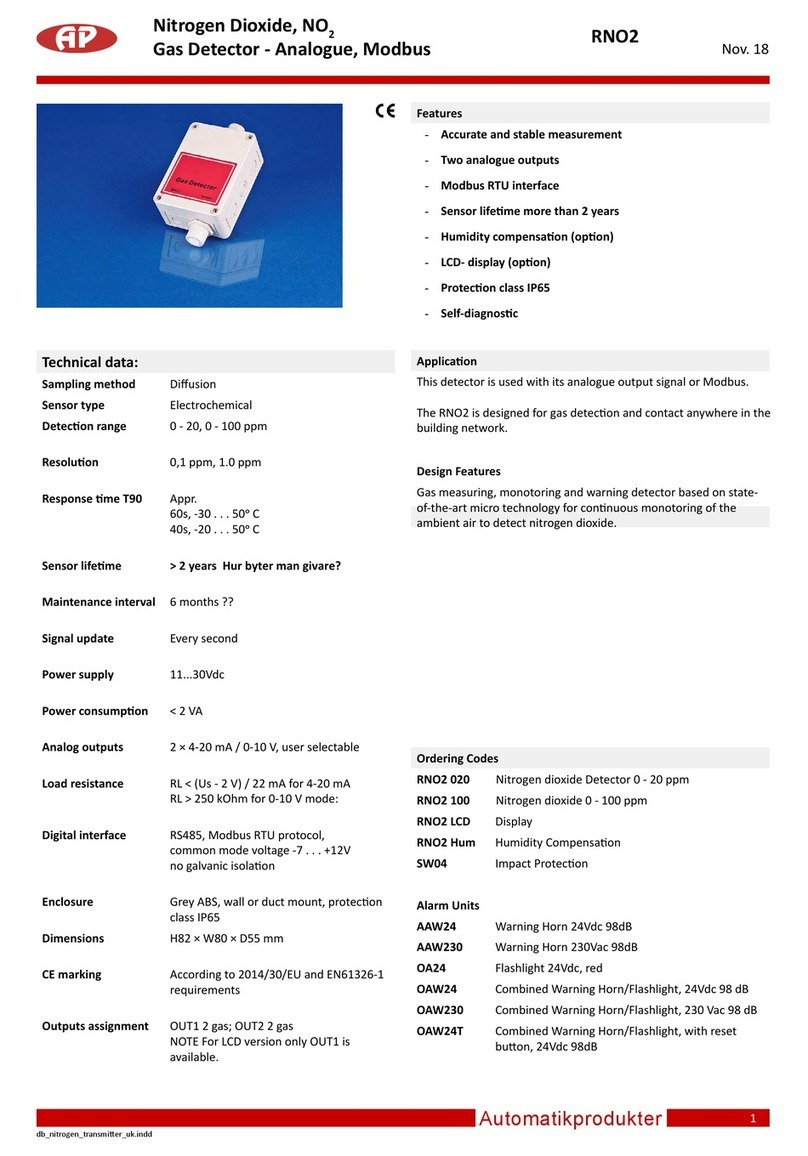
CDH
Manual for Hand Held Carbon
Dioxide and Temperature Monitor
Features
1. Lightweight Made of ABS Plastic.
This durable, lightweight plastic adds
protection while weighing less than one
pound.
2. Display The large display allows for CO2and
Temperature readings at a glance.
The display also allows for adjustments
to mode settings using the push button
interface.
3. Soft Touch Attractive, gives comfort and extra
durability.
4. Up/Down Used to increase or decrease values
Button while the edit mode.
5. Mode Button Toggles between menu options.
6. Power Turns the power on and off.
7. Enter When toggling between menu options,
the Enter button will select desired menu
option for editing (e.g. Altitude settings).
After changes have been made, the
Enter key will also confirm settings and
return to the main menu.
8. Calibration Used for gas connection during
Port calibration or for providing a flow through
sample to the sensor.
9. Calibration Located in the battery compartment, this
Activation switch is used for activating the
Switch calibration process for CO2or Temp.
10. Voltage The sensor is equipped with an output
Output for datalogging. (see accessories).
11. Built-in For continuous monitoring.
Kickstand The built-in kickstand simply swings out
from the base to support the monitor in
an upright position.
12. Power For connecting the supplied 6V power
Connection adapter.
13. Battery 4 AA Batteries are required for portable
Compartment operation.
14. Battery Cover
Accessories
CO2View TM Real-Time Graphing Software & Calibration
This Software allows the CDH to log directly to a Windows
compatible PC and graph concentrations in real time.
Includes graphing software and RS232 connection cable.
All data is stored in a txt.file, which is easily opened by other
programs.
CO2ViewTM also provides and interface that allows the user to
perform a zero and span calibration on the sensor.
Hobo®Datalogger Kit CO2-Temp &RH
This kit includes a tiny data-logger that can record CO2
concentrations from the CDH and also measures temperature
and relative humidity.
The data-logger can be easily attached to the CDH using the
provide VelcroTM strip.
The data-logger can store over 7900 data points and can
sample at a user adjustable time interval.
Also provided with Boxcar software provides basic launch,
data readout. graphing and export capabilities.
Introduction
The CDH is an easy-to-use hand-held CO2/Temperature
monitor.
The unit provides stable, highly accurate readings due to our
patented dual beam NDIR technology.
Equipped with a 0-4 V output, the unit is perfect for long-term
monitoring/recording.
The unit features a large, easy-to-read display with a push-
button interface which al-lows for easy calibration, quick
adjustments for altitude correction, and simple toggling
between °C and °F temperature readings.
A new feature of the sensor now includes the ability to
calculate and display the cfm/person ventilation rate in a
space based on the inside/outside CO2concentration.
1
2
3
4
5
6
7
8
9
10
11
12
13
14
Jan.08

Automatikprodukter
2
Operation
Power-Up
1. Press the Power Button.
2. A 2 second delay will occur before the display
becomes visible.
3. 10 seconds will elapse before current CO2readings
are displayed.
4. “Warm-up” will display for approximately one minute.
During this one minute warm-up, adjustments can not
be made to the sensor.
Elevation Correction - The sensor is shipped with the
elevation setting set at “zero” or sea level. The sensor, like any
other gas measuring device is directly affected by altitude
changes. If you are at an altitude greater than 500 feet, an
adjustment should be made to assure maximum sensor
accuracy. The altitude correction is very small for changes of
500-1000 ft. (e.g. 10-15 ppm/500 ft. increment). Once the
elevation correction is set it will be stored in the monitor
memory and will be retained if the unit is turned off or batteries
removed.
To change the default setting using Elevation Correction
follow the steps below.
1. While in Normal Mode press the “Mode” button once.
The Elevation LCD will begin blinking.
2. Press Enter.
3. Press mode to toggle the elevation reading between
feet (ft) and meters (m)
4. Use the Up/Down button to adjust the alti-tude. The
altitude can be adjusted in increments of 500 (feet) or
100 (meters). Once the correct altitude is set, press
Enter to lock the setting and return to normal mode.
Temperature or Cfm/person - The lower digital display will
cycle through the display of the following units when up/down
buttons are pressed: Temp°F, Temp°C, cfm/person(fm), turn
lower display off.
Stand-alone Monitoring - Once the batteries have been
installed and the Elevation correction has been made (as
described in the steps above), the sensor will begin to
Start-Up
Battery Operation -For portable use, the monitor operates
on 4 AA batteries.
Expected battery life is as follows:
Normal (Non-Alkaline).... Up to 50 hours
Rechargeable.................. Up to 60 Hours
Industrial Alkaline .......... Up to 70 Hours
Display
Listed below are the modes of operation visible on the display.
Warm-Up
When the power button is pressed, the monitor enters a one
minute warm-up indicated by the word WARM-UP in the upper
left corner.
On Line
Indicates when a PC is communicating to the sensor via the
RJ45 port in the rear of the monitor.
Normal Operating Mode
After warm-up the sensor will stabilize and display current
conditions.
Adjustment modes
Pressing the mode button can access adjustment modes. The
following information is displayed for each mode. Once the
mode is displayed, press enter to adjust the setting. Press enter
again to leave the adjustment mode.
Flashing ELEVATION - This feature allows the user to correct
the monitor for elevation changes. ”ELEVATION” will flash in the
lower right corner of the display. Press the enter button and the
current elevation above sea level will be displayed. To change
adjust from ft. to meters press the mode button. Use the up/dwn
buttons to adjust elevation in 500 ft. (100 meter) increments.
When finished with adjustment press enter and the adjustment
will be saved.
Flashing CALIBRATION - When the word ”CALIBRATION”
flashes in the middle of the screen the user can enter the CO2
calibration mode using the procedure described below.
Flashing ”TEMPERATURE” - When the word ”TEMPERA-
TURE” is flashing at the bottom of the screen the user can enter
the Temperature calbration mode using the procedure
described below.
Flashing CO2and ppm
When ”CO2” and ”ppm” are flashing on the screen the user can
enter mode to adjust the outdoor reference concentration for
the cfm/person calculation.
See the procedure below for more information.
Calibration in Progress Mode
Displays when calibration is in progress.
Outdoor Concentration Mode
To properly calculate the ventilation rate in the space the CO2
sensor must know what the outside CO2
concentrations are.
This mode allows the CO2sensor to store in it´s memory the
outside concentration.
It is activated by holding the ”enter button” for 5 seconds when
the monitor is exposed to stabilized outside conditions.
When this feature is activated, CO2, PPM and the lower display
should flash.
The instructions below also describe how the outside concent-
ration can be manually set.
Low Battery - Displays when the power source is low.
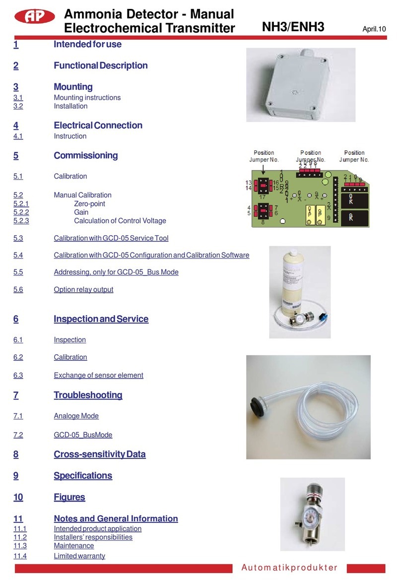
Battery Installation - Remove the battery cover by pressing
the pressure clip (located on the bottom) and pull upward.
Follow the battery diagram imprinted on plastic forproper
installation.
Replace battery cover when battery installation is complete.
Low Battery - A warning signal.
(Low battery), will flash when there is less than 30 minutes of
battery life.
At this point the batteries should be replaced or the AC
adapter should be used as a substitute.
If operation continues, the unit will become inoperable and
only the Low Battery will be blink on the LCD display.
AC Power - The sensor is shipped with a 6 Vdc 500 mA AC/
DC adapter.
To use the AC adapter, connect the plug into the back of the
unit and plug the transformer into any standard wall outlet.
NOTE
Use the supplied adapter.
Using the wrong adapter may cause damage to the unit.
If power is lost during operation, battery operation will not
function as a back up.

Automatikprodukter
3
Calibration (CO2)
IMPORTANT
This CDH has been factory calibrated and should
only need calibration once every 12 months. For the most
accurate field calibration possible we recommend
calibrating this sensor with the AP calibration Kit (part
number CD CAT) available from AP.
In the CDH Monitor, any sensor drift usually occurs at it zero
refernce point. The manual calibration process allows the user
to perform a one point calibration based on ambient levels or
by flowing a gas of a known concentration through the sensor.
This process will adjust the zero offset of the sensor and will
provide an accurate calibration. If for reason a two point
calibration is required the calibration kit or CO2ViewTM
software should be used. To manually calibrate the Model
CDH CO2sensor see instructions below.
1. The calibration procedure will last approximately
15 minutes. Before performing the calibration procedure,
remove the battery cover (see “Battery Installation”) to
provide access to the CO2calibration activation
switch.
Connect the supplied AC adapter to the back of
the sensor.
Ensure the sensor has new batteries or is powered by the
plug in transformer.
2. Power up the sensor and wait for the Warm-up to end.
3. Next verify the Elevation correction has been set.
Refer to the steps in Elevation Correction for procedure.
4. If you are calibrating to ambient conditions make sure the
sensor is displaying a stable reading. It is also very
importent to avoid breathing in the area of the monitor.
If you are flowing gas to the calibration port of the sensor,
allow the gas to flow for at least 10 minutes before initia
ting calibration.
5. Press the Mode button twice. The Calibration mode will
begin blinking.
6. Press Enter.
7. Use the Up/Down Rocker button to adjust the lower
reading on the display to the current ambient conditions.
Pressing the button once will change the readings in
increments of 10 ppm.
To increase the speed, press and hold the button.
NOTE
For best accuracy, a reference or known concentration of CO2
should be used when adjusting the reading.
8. Next, on the backside of the unit locate the push button
switch (under the battery cover, in the small round hole to
the right of the connector jack), use a small pointed object
to depress and hold the switch for 5 seconds.
The Calibration light will begin to blink.
9. Press Enter.
10. Calibration In Progress will begin to blink.
Temperature Adjustment
Use this procedure to adjust the temperature output when, for
example, you wish to have the temperature output match a
reference sensor.
The accuracy of a field adjustment is dependent upon the
stability of the environment is which the procedure is perfor-
med, and upon the accuracy of the reference sensor.
1. Before performing the temperature adjustment, connect
the supplied AC adapter to the back of the sensor. If
you do not have the AC adapter, new batteries should
be used.
2. Power up the sensor and, using the kickstand, place it
on a flat surface in a stable environment relatively free
of drafts or temperature changes. Wait 30 minutes for
the unit to fully equilibrate with the environment. Do not
hold the unit in your hand during this period.
3. Press the Mode button a number of times. until the
blinking word “TEMPERATURE” appears.
4. Press Enter. Both the word “TEM-PERATURE” and the
numeric temperature display will begin blinking in unison.
5. Use the Up/Down Rocker button to adjust the temperature
reading to match the reference.
6. Press Enter. The temperature offset is immediately
adjusted, the blinking stops, and the unit is now in normal
operating mode.
accurately display current room conditions.
Kickstand - The sensor is equipped with a kickstand which
can be used for desktop monitoring.
Using an External Datalogger - Voltage outputs for both CO2
and temperature are available via an RJ-45 jack on the rear of
the unit.
Ventilation Rate Indicator (cft)
Overwiew - To display the ventilation rate scroll through the
up/down button until the lower display provides a reading
showing ftm, which stands for cfm (cubic feet per minute). This
value represents how much outside air is being introduced on
a cfm per person basis in the space. Current codes and
standards generally require 15 to 20 cfm/person to be
delivered to most spaces to ensure acceptable indoor air
quality. Lower cfm/person values will indicate lower levels of
ventilation and potentially poor air quality. Higher levels will
indicate excessive ventilation and potential excessive energy
usage. Accurate interpretation of the ventilation rate indicator
requires a measurement be take 2 to 3 hours after occupancy
has stabilized in a space or at a peak in daily CO2
concentrations. In other conditions the indicator may tend to
over estimate ventilations rates. The calculation of ventilation
rates also assumes an office type of activity level (sitting some
walking and other low level activity). If activity levels are
higher the sensor will also underestimate the ventilation rate.
The CDH will calculate the outside air ventilation rate to a
space based on the inside/outside CO2 differential readings.
The sensor is factory set to assume an outside level of 400
ppm, which should be close to the outside concentration in
most areas. The outside level of CO2 can also be changed by
measuring outside levels or by manually adjusting the
monitor.
Adjustment - To measure readings, take the unit outside and
wait for levels to stabilize on the CO2display (should take
approximately 5 minutes). Once levels have stabilized, hold
the ”enter” button on the sensor for 5 seconds.
At this point the unit will program itself based on the CO2
value that was input in Step 6.
The calibration process will take approximately 5 minutes.
When Calibration is complete, the display will return to the
steady Calibration mode.
Press Enter to return to the normal operation mode.

Automatikprodukter
4
Vi förbehåller oss rätten att göra ändringar utan föregående meddelande.
Specifications
Method
Dual Beam Absorption Infrared™
Sample Method
Diffusion or flow through (50 - 100 ml/min)
Warranty
18 months parts and labor
Performance
CO2Channel Measurement Range
0-4,000 ppm voltage output
0-10,000 ppm display
Resolution
± 1 ppm
Accuracy
±50 ppm or ±5% of reading, whichever is greater
Repeatability
±20 ppm
Temperature Dependence
±0.1% of reading per °C or ±2 ppm per °C,
whichever is greater, referenced to 25°C
Pressure Dependence
0.13% of reading per mm Hg
(Corrected via user input for elevation)
Annual Drift
± 20 ppm typical
Response Time
<60 seconds for 90% of step change
Warm-Up Time
<60 seconds at 22°C
Operating Conditions
32...122°F (0...50°C)
0-95% RH, non-condensing
Storage Temperatures
-40...140°F (-40...60°C)
Calibration Interval
12 months, offset adjustment using single
gas at 0-1000 ppm CO2. Full factory calibration available
Temperature Channel
Temperature Range
Voltage output 32...104°F (0 to 40°C)
Display 32...122°F (0 to 50°C)
Display Resolution
0.1°F (0.1°C)
Display Options
°F, °C, or Off. Set with panel button.
Accuracy
±2°F (±1°C)
Response Time
20-30 minutes (case must equilibrate with environment)
Calibration Interval
12 months, offset adjustment using
temperature standard at 50...86°F
(10...30°C). Full factory calibration available
Output - Analog
CO2
0-4 Vdc, 1mV/ppm (4,000 ppm max)
Temperature
0-4 Vdc linear, 32-104°F (0-40°C)
Output Impedance
100 Ohms
Wiring Connection
Via RJ-45 to (accessory cable 2070 or 2071)
Output - Digital
Wiring Connection
Via RJ-45 to DB9 serial port cable
Display
LCD with independent CO2/ temperature
readings (panel buttons set elevation, °F/°C,
calibration functions)
Power Supply
Battery Type
Four AA batteries, not included
Battery Operation
70 hours (alkaline)
External
6 Vdc from external AC/DC adapter, included
Power Requirements
100 mA Peak, 20 mA average from 6 V
Certification
FCC Class 15 Part B
Accessories
CD CA Datalogging cable (analogo utput)
CD CR Datalogging cable Recordaire ®
CD CAT Calibration kit
CD DSW CO2View Datalogging Software
CD LOG Datalogging Kit with Temp/RH
CD DL Recordaire ®datalogger, 4-channel
CD GSW VG Graphing software
This will store the outside reading in the monitor memory and
use this value to calculate the ventilation rate based on the
differential of the measured outside value and into measured
inside concentration. The monitor will remember this outside
value until a new value is entered.
Manual Input Of Outside Concentration - The outside
reading can also be manually set using the on-board keypad
and display (default is 400 ppm). The monitor assumes that
the activity level (and related CO2production) in the space is
similar to that of a office environment (1.2 MET). To manually
adjust the assumed outside concentration for the internal cfm/
person calculation or to check the current CO2level program-
med into the monitor, use the following procedure.
1. Once the CDH has warmed up, press the mode button a
number of times until ”CO2” and ”ppm” indicators are
flashing.
2. Press the enter button and the current assumption for
outside levels will be didplayed.
3. Using the up/down scroll button adjust the outside level to
the desired level.
4Press enter to store the value in the monitor.
Other AP Gas Detector manuals
Popular Gas Detector manuals by other brands

Spectrex
Spectrex SafEye Quasar 950 Manual supplement

Wetekom
Wetekom 82 72 76 instruction manual

CGS
CGS MINI MERLIN Installation operation & maintenance

Rothenberger
Rothenberger ROTEST Electronic 4 Instructions for use

AGS
AGS Mini Merlin LPGCO v2 TX Installation, operation & maintenance manual

System Sensor
System Sensor CO1224T Frequently asked questions