DEGA NB III LCD User manual

INSTRUCTION
MANUAL
Gas detector
DEGA NB III LCD
Reproduction of this manual or any part thereof, in any form, without the prior permission of DEGA.CZ s.r.o. is
prohibited
DEGA CZ s.r.o. reserves the right to alter the specifications of the hardware and software described in this manual at
any time and without prior notice
DEGA CZ s.r.o. bears no liability for any damage resulting from use of this device

Content
For your safety ..................................................................................................................................................................................
Technical data and information ........................................................................................................................................................ 3
Operational and storage conditions ................................................................................................................................................. 4
Terminology ...................................................................................................................................................................................... 4
Product description ........................................................................................................................................................................... 4
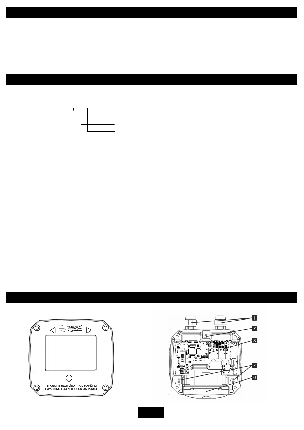
Installation, assembly and disassembly of the detector ................................................................................................................... 5
1. Assembly of the detector ...................................................................................................................................................... 5
. Replacement of the sensor module ...................................................................................................................................... 5
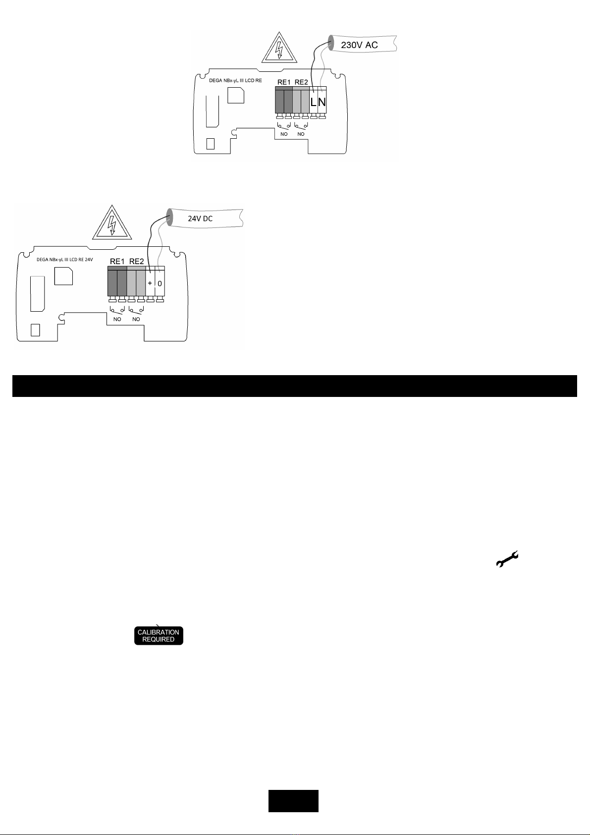
3. Connecting the detector - 30V AC ..................................................................................................................................... 6
4. Connecting the detector - 4V. Only for version NBx-yL III LCD RE 4V. ............................................................................. 6
Detector functions ............................................................................................................................................................................ 6
1. Turning on the detector ........................................................................................................................................................ 6
. Gas detection ........................................................................................................................................................................ 6
3. Malfunction ........................................................................................................................................................................... 6
4. Monitoring the calibration periods ....................................................................................................................................... 6
5. Reading the record of measured concentrations and alarms .............................................................................................. 6
Detector controls .............................................................................................................................................................................. 7
6. Menu History „HIST“ ............................................................................................................................................................. 8
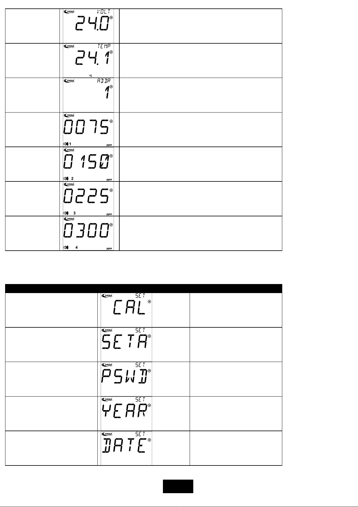
7. Information menu „INF“ ....................................................................................................................................................... 8
8. Settings menu „SET“ ............................................................................................................................................................. 9
9. Menu Test „TEST“ ............................................................................................................................................................... 11
Operation and maintenance of the detector.................................................................................................................................. 11
1. Usage limits ......................................................................................................................................................................... 11
. Operation ............................................................................................................................................................................ 1
3. Operation/Maintenance ..................................................................................................................................................... 1
Accessories ...................................................................................................................................................................................... 1
1. Additional bushing DEGA BUSHING for NBx III ....................................................................................................................... 1
Basic type of detectors ................................................................................................................................................................... 1
1. Detectors with a catalytic sensor NBx-CL III LCD ................................................................................................................ 1
. Detectors with an electrochemical sensor NBx-EL III LCD .................................................................................................. 13
3. Detectors with an infrared sensor NBx-IL III LCD ................................................................................................................ 15
4. Detectors with a semiconductor sensor NBx-SL III LCD ...................................................................................................... 15
5. Detectors with a PID sensor NBx-PID III LCD ...................................................................................................................... 15
Add-on modules .............................................................................................................................................................................. 16
Attachments .................................................................................................................................................................................... 16
Table of error codes.................................................................................................................................................................... 16
General warranty terms and conditions ......................................................................................................................................... 17
For your safety
The detector must e mounted with the sensor module downwards
To maintain IP protection, the detector must be mounted with the sensor module downwards
Beware of static electricity
Electronic components are sensitive to static electricity. Do not touch them directly - they may get damaged.
The device is intended to e installed y a trained person
The product is designed only for installation by a certified technician. The manufacturer is not liable for damages resulting
from incorrect or improper handling.
In case of malfunction, immediately unplug from the power supply
If you notice an unusual smell or smoke emitting from the product, unplug it from the power supply, battery backup and all
other attachments. Continued operation could result in injury or property damage.

3
The detector is intended for use exclusively in a non-explosive environment
Detectors DEGA NSx-yL II (ZONE ) and NSx-yL III (ZONE 1) are designed for use in potentially explosive environment.
Do not disassem le the product and ensure against the contact of its internal components with water
Contact of internal components of the product with water may cause an electric shock. In case of any malfunction entrust the
servicing of the product exclusively to a certified service centre. Contact with water can create a short circuit in the product
and consequent damage to property or personal injury.
Use appropriate ca le types
To ensure compliance with the parameters of the product, only use the recommended cable types described in this manual.
Dispose of used products and detector sensors with respect to the environment
Detector sensors contain hazardous substances. Dispose of them in accordance with the current legislation on environmental
protection.
Use the detector only with the appropriate certified DEGA products
The device is certified as functionally and technically qualified only with original "DEGA" accessories. In case of using the
device with any other products the manufacturer is not liable for any damages that may occur.
Undertake regular functional checks and cali rations of the detector
Perform regular "CALIBRATION" (setting the detection limits, checking the responsiveness of the sensor, checking the
functionality of the detector) and "OPERATIONAL AND FUNCTIONAL CHECKS" of the entire detection system (sensor excitation
with subsequent control of optical and audible alarms, triggering fans, shutdown technology, etc.). Perform calibration and
operational and functional checks only at certified service centers with a valid certificate of competence or at the
manufacturer.
Warning: The detector automatically checks it's calibration period - the period of validity of it's calibration. After 1 months since the last calibration (max.
calibration period) the detector will transmit this fact to the host system. The detector must be calibrated immediately at a certified service center with a
valid certificate of competence or by the manufacturer. See section "Monitoring the calibration periods".
Technical data and information
Supply voltage: 30 V/ AC
Wire diameter range: 0,08- ,5 mm
– wire, stranded wire 0, 5-1,5 mm
– stranded wire with ferrule
Output: x potential free relay
Dimensions without bushings 110 x 100 x 50 mm (WxHxD)
Weight: 0,3 kg
Input
Warm
-
Up time
DEGA N
Bx
-
EL III LCD
1,1 W
DEGA NBx
-
EL III LCD
max. 180 s
DEGA NBx
-
CL III LCD
, W
DEGA NBx
-
CL III LCD
max. 30 s
DEGA NBx
-
IL III LCD
1,7 W
DEGA NBx
-
IL III LCD
max. 15 s
DEGA NBx
-
SL III LCD
1,7 W
DEGA NBx
-
SL III LCD
max. 180 s
DEGA NBx
-
PL III
PID LCD
, W
DEGA NBx
-
PL III LCD PID
max. 15 s
Consumption/input
in the ALARM mode
Time to sta ilize
(>
5 days without power
)
DEGA NBx
-
EL III LCD
, W
DEGA NBx
-
EL III LCD
1
-
7 h
DEGA NBx
-
CL III LCD
3,3 W
DEGA NBx
-
CL III LCD
max. 1 h
DEGA NBx
-
IL
III LC
D
,8 W
DEGA NBx
-
IL III LCD
max. 30 min
DEGA NBx
-
SL III LCD
,8 W
DEGA NBx
-
SL III LCD
max. 1 h
DEGA NBx
-
PL III LCD PID
3,3 W
DEGA NBx
-
PL III LCD PID
max. 30 min
Response time
(T90)
Sensor lifetime in a clean environment
DEGA NBx
-
EL III LCD
max.
1
80 s
-
based on sensor type
DEGA NBx
-
EL III LCD
years
DEGA NBx
-
CL III LCD
max. 30 s
DEGA NBx
-
CL III LCD
years
DEGA NBx
-
IL III LCD
max. 30 s
DEGA NBx
-
IL III LCD
5 years
DEGA NBx
-
SL III LCD
max. 30 s
DEGA NBx
-
SL III LCD
years
DEGA NB
x
-
PL I
II
LCD PID
max. 30 s
DEGA NBx
-
PL III LCD PID
years

4
Operational and storage conditions
Ambient temperature: - 0 °C to +60 °C (electrochemical, semiconductor and catalytic sensors) - 0 °C až +40 °C
(infrared sensors)
Relative humidity: 0-95 % RH
Air pressure: 80-1 0 kPa
Ambient air flow: max. m/s - flow directly to the sensor in not allowed
IP rating: IP 54
Location: BE1 - non-explosive atmospheres
Terminology
The marking system for detector
DEGA NBx-yL III LCD :
Gas detector
DEGA NBx-yL III LCD
Series of detectors for non-explosive atmospheres
Type of gas detected
Sensor typ with linear output
Third generation product with DEGA design
DEGA NBx-EL III LCD with an electrochemical sensor
They operate on the principle of change of electrical parameters on the electrodes stored in electrolyte, due to oxidation or
reduction reactions of the detected gas on its surface. These sensors have good selectivity and the ability to detect very low
concentrations of toxic gases.
DEGA NBx-CL III LCD with a catalytic sensor (Pelistor)
They operate on the principle of catalytic combustion - gas concentration is measured based on the amount of heat released
in a controlled combustion reaction. The reaction is supported by a suitable temperature and the presence of a catalyst. These
sensors can be used to detect a broad range of flammable gases. The sensors are characterized by fast response, long lifetime
and high stability. A minimum of 10 % of Oxygen in the air is required for their proper function.
DEGA NBx-IL III LCD with an infrared sensor (NDIR)
Top quality scanning method. They operate on the principle of infrared spectroscopy. The sensors have excellent selectivity in
organic matter, do not require any oxygen in the atmosphere and are resistant to catalyst poisons (sulfur and silicon
compounds) which cause a change of sensitivity of catalytic sensors. The sensors are also characterized by high stability and a
long lifetime.
DEGA NBx-SL III LCD with a semiconductor sensor
The sensors operate on the principle of changes in electrical conductivity of semiconductors by changing the concentration of
the detected gas. Their advantage is a long lifetime in a clean environment and a wide range of different types of gases and
vapors. Their disadvantage is their low selectivity - the sensor largely responds to other gases, for which it is not calibrated.
DEGA NBx-PL III LCD PID with a photoionization sensor
Sensitive scanning method for detection of a wide range of VOC - volatile organic compounds. The sensor does not selectively
detect all VOCs in the air at concentrations in ppm.
Product description

5
Bushings
Allen screws 3mm
Magnetic control
„BACK“
Magnetic control
„FRONT“
Magnetic control
„ENTER/EXIT“
Sensor module
PCB with
electronics
PCB with electronics
Power supply
terminal block 30V
- L
Power supply terminal
block 30V - N
Relay outputs
terminal block
Connector for service
operations
Installation, assem ly and disassem ly of the detector
Before assembling, read the valid installation standards ČSN EN 60079- 9- (Selection, installation, use and maintenance of
detectors for combustible gases and oxygen) and ČSN EN 45544-4 (Guidelines for the selection, installation, use and
maintenance of detectors of toxic substances).
Make certain that the sensor input is accessible by air. The detector must be in an open area with no obstacles in its way
(furniture etc.) Ensure that the input of the sensor is not be polluted by layers of dust or otherwise contaminated.
To maintain IP protection, the detector must e mounted with the sensor down.
1. Assem ly of the detector
The detector consists of four parts - the body of the detector, the removable sensor and bushings.
Detector assembly procedure is to be performed in the following steps:
a) Disassemble the detector using four hexagon socket 3 mm screws
b) Use a screwdriver to break out holes for the bushings
c) Mount the detector on a flat surface using three 6 mm fasteners in a height above the floor with the gas entrance
facing downwards, according to the specifications of the detected substance
d) Direct the cables trough the bushings
e) Connect the wiring to the terminal block of the detector
f) Assemble the detector using four hexagon socket 3 mm screws
. Replacement of the sensor module
This activity must not be performed when the detector is energized
.
In case of need to replace the sensor module with a new piece, unscrew and remove the
cover. Unscrew a pair of 3 mm hexagon screws on the sensor module and carefully remove
the sensor module so as not to damage the pins of the sensor unit. Carefully insert the new
sensor module – be careful not to bend the pins! Screw the two 3 mm hexagons screws and
put back the cover. Screw the cover.
8
7
6
5
4
3
1
2
1
2
3
4

6
3. Connecting the detector - 230V AC
4. Connecting the detector - 24V. Only for version Bx-yL III LCD RE 24V.
Detector functions
1. Turning on the detector
When the detector power is switched on, automatic test procedures begin, which can take up to 180 seconds, depending on
the sensor used. During this sequence, the internal electronics are tested and the sensor is stabilized to prevent false alarms
after switching on. At this time, only the time (glow) until the start of the measurement is shown on the display. After forming,
the detector starts measuring values and works according to its settings.
. Gas detection
The detector continuously measures the concentration of the detected gas in the atmosphere.
3. Malfunction
In case of malfunction the LCD screen displays the measured concentration, an error code and a key symbol . On the PCB,
this condition is indicated by the yellow „ERR“ LED. The meaning of each error code is explained in Attachment .
4. Monitoring the calibration periods
The detector continuously checks the calibration validity of the connected sensor. After 1 months from the last calibration
(max. calibration interval), flashes on the LCD display. The connected sensor must be calibrated immediately.
5. Reading the record of measured concentrations and alarms
The detector periodically, after 60 s, stores the current detected concentration into its internal memory. The internal memory
retains data from the last 64 60 measurements (cca 44 days). In order to read this information, the program DegaConfig is
required. See the DegaConfig program user manual.

7
Detector control
The detector equipped with an LCD display can be controlled by the magnetic contact located on the sides of the display.
Warning: calibration
required
Warning: Service is
required
Data display
Time display
Channel number
(address)
Activated magnetic
control
Calibration icon
Communication with the
control panel in
progress
Measured value
Bar graph of the
measured value
Measured value
units
Alarm PEL (long
-
term
exposure limit
exceeded)
Alarm STEL (short
-
term exposure limit
exceeded)
Alarm level reached,
alarm level
Alarm indication
-
„BACK“
move backwards in the menu, reducing the
value
-
„FRONT“
move forwards in the menu, increasing the
value
-
„ENTER“
confirm/enter the m
enu
Placing a magnet into the indent „ “ for 5 s activates the magnetic control, which is displayed by the icon „ “ on the LCD.
Reaching level 4 alarm in case of catalytic and semiconductor sensors causes a ratchet phenomenon, where even after
recovery from gas leak, the detector is still in level 4 alarm and needs to e manually reset y pressing „ “.
Main menu structure:
Enter the 5 s menu by holding down the magnet
|
History->-Information->-Settings->- Test->- Exit
|-----------------------<------------------------------|
Menu
Display
Description
History
Browsin
g
the alarm hi
story
Information
Information about detector settings
Settings
Detector configuration
15
14
1
3
12
11
10
9
8
7
6
5
4
3
2
1

8
Test
Testing the detector functions
Exit
Return to normal oper
ation
6. Menu History „HIST“
Browsing the history
Menu
Display
Description
History
of all
alarms
Use „ “ to go trough individual alarms. Displays the
date and time of the alarm. Return to the history menu
„ “
Highest
concentration in
the past hour
Displays the highest measured concentration and alarm
for the past hour. Return to History menu „ “
Highest
concentration in
the past 8 hours
Displays the highest measured concentration and alarm
for the past 8 hours. Return to History menu „ “
Highest
concentration in
the past 12 hours
Displays the highest measured concentration
a
nd alarm
for the past 1 hours. Return to History menu „ “
Highest
concentration in
the past 12 hours
Displays the highest measured concentration and alarm
for the past 4 hours. Return to History menu „ “
Highest
concentration
stored in the
memory
D
isplays the h
ighest measured concentration and alarm,
that is stored in the memory. Return to History menu
„ “
Exit
Return to the main menu
7. Information menu „I F“
Information about settings. Sequentially displays the following information. Access previous information by pressing „ “
Menu
Display
Description
Date of next
cali ration
Displays the date of the next calibration
Date of last
cali ration
Displays the dat
e of the last calibration

9
Power voltage
Displays the power voltage
Temperatur
e
Displays
the chip temperature (about 15°C higher than
the ambient temperature)
RS485 device
address
Displays the device address
Alarm level 1
Displays alarm level 1
Alarm level 2
Displays alarm level
Alarm level 3
Displays alarm level 3
Alarm level
4
Displays alarm level 4
8. Settings menu „SET“
Protected by password 0004. After entering a wrong password, the detector returns to measurement mode.
The password can be changed in the menu SET -> PSWD.
Menu
Display
Description
Cali ration
Sensor cal
ibration
Setting the alarms
Setting the alarms
Changing the password
Setting the year
Setting the year
Setting the date
Setting the date

10
Setting the time
Setting the time
Exit
Return to the main menu
Cali ration
a) Connect fresh air to the sensor input. The icon
„ “
flashes
.
After the value stabilizes, move onto the next step using
„ “
b) Using „ “ select the concentration of the calibration gas, confirm „ “
c) Connect the calibration gas to the sensor input. The icon „ “ flashes. Wait until the value sta ilizes and confirm
„ “
d) Using „ “ switch between „YES“ - save calibration, or „NO“ - return to the Settings menu. Confirm the selected
option „ “
e) In case of saving a new calibration, the detector will restart after 5 s.
Setting the alarms
a) Using „ “ select the concentration for alarm 1. Confirm „ “
b) Using „ “ select the concentration for alarm . Confirm „ “
c) Using „ “ select the concentration for alarm 3. Confirm „ “
d) Using „ “ select the concentration for alarm 4 Confirm „ “
e) Using „ “ switch between „YES“ - save settings, or „NO“ - return to the Settings menu. Confirm the selected
option „ “
Setting the range of the 20mA current loop
a) Using „ “ select the concentration appropriate to 0mA range. Confirm „ “
b) Using „ “ switch between „YES“ - save settings, or „NO“ - return to the Settings menu. Confirm the selected
option „ “
Changing the password
a) Using „ “ select a number in thousands. Save the selected number „ “
b) Using „ “ select a number in hundreds. Save the selected number „ “
c) Using „ “ select a number in tens. Save the selected number „ “
d) Using „ “ select a number in units. Save the selected number „ “
e) Using „ “ switch between „YES“ - save settings, or „NO“ - return to the Settings menu. Confirm the selected
option „ “
Setting the year
a) Using „ “ select a number in thousands. Save the selected number „ “
b) Using „ “ select a number in hundreds. Save the selected number „ “
c) Using „ “ select a number in tens. Save the selected number „ “
d) Using „ “ select a number in units. Save the selected number „ “
e) Using „ “ switch between „YES“ - save settings, or „NO“ - return to the Settings menu. Confirm the selected
option „ “

11
Setting the date
a) Using „ “ select a number in thousands. Save the selected number „ “
b) Using „ “ select a number in hundreds. Save the selected number „ “
c) Using „ “ select a number in tens. Save the selected number „ “
d) Using „ “ select a number in units. Save the selected number „ “
e) Using „ “ switch between „YES“ - save settings, or „NO“ - return to the Settings menu. Confirm the selected
option „ “
Setting the time
a) Using „ “ select a number in thousands. Save the selected number „ “
b) Using „ “ select a number in hundreds. Save the selected number „ “
c) Using „ “ select a number in tens. Save the selected number „ “
d) Using „ “ select a number in units. Save the selected number „ “
e) Using „ “ switch between „YES“ - save settings, or „NO“ - return to the Settings menu. Confirm the selected
option „ “
9. Menu Test „TEST“
Protected by password 0004. By entering a wrong password, the detector returns to measurement mode.
The password can be changed in the menu SET -> PSWD.
Menu
Detector restart
Using „ “ switch between „YES“ - for restart, or „NO“ for returning to
Test menu. Confirm „ “.
Return to main menu
Return to main menu
Operation and maintenance of the detector
1. Usage limits
To maintain proper operation of the detector it is necessary to respect the fact that step changes of humidity, condensation or
rapid changes of pressure can cause incorrect indication of the measured value. Each sensing technology is suited for different
methods of application, as described below. All sensors are characterized by a smaller or larger cross-sensitivity to other gases
than those which they are set for. Therefore we recommend to have the air in the deployment area of the detection system
analyzed before processing project documentation.
a) catalytic sensors: Trace amount of vapors of silicon compounds and sulfur compounds cause a permanent loss of sensitivity,
which requires recalibration or replacement of the sensor. Longterm crossing of the measuring range causes a decrease in
sensitivity. In case of an atmosphere with oxygen content of less than 17%, there measured value will be overvalued. In case of
an atmosphere with oxygen content of more than 5%, the measured value will be undervalued.
b) electrochemical sensors: Constant exposure to toxic gases or short-term exposure to gases, which greatly exceed the
maximum range of the sensor, can damage the electrochemical sensor, which requires recalibration or replacement. High
temperature along with low relative humidity have a negative effect on the sensor's lifetime. In case of an atmosphere with
oxygen content of less than 1% for longer than 1 hour, the measured value will be undervalued.
c) infrared sensors: Vapor acids and alkalis can etch the optical system and distort the measurements. A check or a calibration
may be necessary.

1
d) semiconductor sensors: Short-term exposure to gases or vapors of organic solvents, which greatly exceed the maximum
range of the sensor, may damage the sensor and a recalibration or replacement may be required. In case of an atmosphere
with an oxygen content of less than 18 %, the measured value will be undervalued.
e) photoionization sensors: the UV lamp or sensor must be replaced regularly, as its clogging of can cause loss of signal.
. Operation
To maintain proper operation of the detector it is necessary to respect the fact that the presence of certain concentrations of
gases or vapors, other than those for which the sensor is set, can cause an alarm, even if the concentration of the gas does not
exceed the set level. Given the range of disturbing gases or vapors (diluents, exhaust gases, vapors of organic substances,
disinfectants, etc.) a generally allowable concentration of interfering gases can not be determined. Data on cross-sensitivity to
certain gases are listed at the appropriate sensors. Therefore we recommend to have the air in the deployment area of the
detection system analyzed before processing project documentation.
3. Operation/Maintenance
In case of contamination, the surface can be cleaned with a slightly moistened cloth.
The sensors have a different lifetime depending on the sensing technology used and on environmental conditions.
Characteristics of the sensors vary over time. Therefore it is required to perform regular checks and calibrations, which can
commence in two ways:
a) 1 x per 6 months carry out a „cali ration“ and functional control - adjust the sensitivity of the sensor using calibration
gas and check the functionality of the system. The exact interval depends on the purity of the environment, required
accuracy and the occurrence of disturbing gases in the atmosphere.
b) 1 x per 12 months carry out a „cali ration“ - adjust the sensitivity of the sensor using calibration gas and check the
functionality of the system. The exact interval depends on the purity of the environment, required accuracy and the
occurrence of disturbing gases in the atmosphere. Also carry out a „functional control" 1 x per three months - checking
the function of the entire detection system using a test gas, which does not exceed the range of the sensor. We
recommend using gas intended for laboratory use.
Perform calibration only at certified service centers with a valid certificate of competence or at the manufacturer.
For the Czech Repu lic only DEGA CZ s.r.o.
Accessories
1. Additional bushing DEGA BUSHI G for Bx III
PG9
Basic type of detectors
1. Detectors with a catalytic sensor Bx-CL III LCD
Product code Detector type Detected gas Measurement
range
Measurement of
current loop
(4- 0 mA)
Resolution Calibration gas
20100169
DEGA NBM-CL 100 III LCD
Methane (CH4)
Natural gas
CNG
0–100 % LEL 0- 0 % LEL 0,1 % LEL Methane 0,88 %
20100170
DEGA NBP-CL 100 III LCD
Butane (C4H10)
Propan-Butane
LPG
0–100 % LEL 0- 0 % LEL 0,1 % LEL Butane 0,3 %
20100171
DEGA NBH-CL 100 III LCD
Hydrogen (H ) 0–100 % LEL 0- 0 % LEL 0,1 % LEL Hydrogen 0,8 %
20100168
DEGA NBHC-CL 100 III LCD
Other
flammable and
combustible
gases and
vapors
according to
the selectivity
of the sensor
0–100 % LEL 0- 0 % LEL 0,1 % LEL According to the selectivity of the
sensor

13
. Detectors with an electrochemical sensor Bx-EL III LCD
Product code Detector type Detected gas Measurement
range
Measurement of
current loop
(4- 0 mA)
Resolution Calibration gas
20100122
DEGA NBCO-EL 1000 III LCD
Carbon
Monoxide (CO) 0–1000 ppm 0-130 ppm 1 ppm Carbon Monoxide
450 ppm
20100119
DEGA NBCO-EL 00 III LCD
Carbon
Monoxide (CO) 0– 00 ppm 0- 00 ppm 0,1 ppm Carbon Monoxide
130 ppm
20100120
DEGA NBCO-EL 500 III LCD
Carbon
Monoxide (CO) 0–500 ppm 0- 00 ppm 0,1 ppm Carbon Monoxide
130 ppm
20100121
DEGA NBCO-EL A500 III LCD
Carbon
Monoxide (CO) 0- A500 ppm 0-500 ppm 1 ppm Carbon Monoxide
130 ppm
20100123
DEGA NBCO-EL 000 III LCD
Carbon
Monoxide (CO) 0– 000 ppm 0- 000 ppm
1 ppm Carbon Monoxide
130 ppm
20100139
DEGA NBA-EL 100 III LCD
Ammonia
(NH3)
0-100 ppm
0-50 ppm
0,1 ppm
Ammonia
100 ppm
20100141
DEGA NBA-EL 1000 III LCD
Ammonia
(NH3)
0-1000 ppm
0-300 ppm
1 ppm
Ammonia
100 ppm
20100144
DEGA NBA-EL 10000 III LCD
Ammonia
(NH3)
0-10000 ppm
0-10000 ppm
1 ppm
Ammonia
100 ppm
20100140
DEGA NBA-EL 500 III LCD
Ammonia
(NH3)
0-500 ppm
0-500 ppm
1 ppm
Ammonia
100 ppm
20100143
DEGA NBA-EL 5000 III LCD
Ammonia
(NH3)
0-5000 ppm
0-5000 ppm
1 ppm
Ammonia
1000 ppm
20100142
DEGA NBA-EL 000 III LCD
Ammonia
(NH3)
0- 000 ppm
0- 000 ppm
1 ppm
Ammonia
1000 ppm
20100116
DEGA NBCL -EL 0 III LCD
Chlorine
(Cl ) 0- 0 ppm 0-5 ppm 0,01 ppm Chlorine
5 ppm
20100117
DEGA NBCL-EL 00 III LCD
Chlorine
(Cl )) 0- 00 ppm 0- 00 ppm 0,1 ppm Chlorine
50 ppm
20100151
DEGA NBO -EL 30 III LCD
Oxygen (O ) 0-1 % 0-1 % 0,01 % Air
20100152
DEGA NBO -EL T30 III LCD
Oxygen (O ) 0-100 % 0-30 % 0,1 % Air
20100153
DEGA NBO -EL T100 III LCD
Oxygen (O ) 0-100 % 0-30 % 0,1 % Air
20100155
DEGA NBO3-EL 5 III LCD
Ozone (O3) 0-5 ppm 0-0, ppm 0,01ppm Chlorine
5 ppm
20100154
DEGA NBO3-EL 100 III LCD
Ozone (O3) 0-100 ppm 0-100 ppm 0,1ppm Chlorine
5 ppm
20100135
DEGA NBHCL-EL 0 III LCD
Hydrogen
chloride (HCl) 0- 0 ppm 0-10 ppm 0,01 ppm Hydrogen chloride
10 ppm
20100136
DEGA NBHCL-EL 00 III LCD
Hydrogen
chloride (HCl) 0- 00 ppm 0- 00 ppm 0,1 ppm Hydrogen chloride
5 ppm
20100132
DEGA NBH S-EL 50 III LCD
Hydrogen sulfide
(H S) 0-50 ppm 0-15 ppm 0,1 ppm Hydrogen sulfide 5 ppm
20100130
DEGA NBH S-EL 500 III LCD
Hydrogen sulfide
(H S) 0-500 ppm 0-500 ppm 1 ppm Hydrogen sulfide 500 ppm
20100129
DEGA NBH S-EL 100 III LCD
Hydrogen sulfide
(H S) 0-100 ppm 0-100 ppm 0,1 ppm Hydrogen sulfide 5 ppm
20100131
DEGA NBH S-EL 000 III LCD
Hydrogen sulfide
(H S) 0- 000 ppm 0- 000 ppm 1 ppm Hydrogen sulfide 000 ppm
20100148
DEGA NBNO -EL 0 III LCD
Nitrogen dioxide
(NO ) 0- 0 ppm 0-15 ppm 0,01 ppm Nitrogen dioxide 0 ppm
20100149
DEGA NBNO -EL 100 III LCD
Nitrogen dioxide
(NO ) 0-100 ppm 0-100 ppm 0,1 ppm Nitrogen dioxide 0 ppm
20100150
DEGA NBNO -EL 500 III LCD
Nitrogen dioxide
(NO ) 0-500 ppm 0-500 ppm 1 ppm Nitrogen dioxide 100 ppm
20100146
DEGA NBNO-EL 50 III LCD
Nitric oxide (NO) 0- 50 ppm 0-15 ppm 0,1 ppm
Nitric oxide 150 ppm
20100145
DEGA NBNO-EL 5 III LCD
Nitric oxide (NO) 0- 5 ppm 0- 5 ppm 0,1 ppm
Nitric oxide 15 ppm
20100147
DEGA NBNO-EL 1000 III LCD
Nitric oxide (NO) 0-1000 ppm 0-100 ppm 1 ppm
Nitric oxide 10 ppm

14
20100164
DEGA NBSO -EL 0 III
LCD
Sulfur dioxide
(SO ) 0- 0 ppm 0-3,5 ppm 0,01 ppm Sulfur dioxide 4 ppm
20100165
DEGA NBSO -EL 00 III
LCD
Sulfur dioxide
(SO ) 0- 00 ppm 0- 00 ppm 0,1 ppm Sulfur dioxide 50 ppm
20100166
DEGA NBSO -EL 000 III LCD
Sulfur dioxide
(SO ) 0- 000 ppm 0- 000 ppm 1 ppm Sulfur dioxide 1000 ppm
20100161
DEGA NBSO -EL 100 III LCD
Sulfur dioxide
(SO ) 0-100 ppm 0-100 ppm 0,1 ppm Sulfur dioxide 50 ppm
20100162
DEGA NBSO -EL 1000 III LCD
Sulfur dioxide
(SO ) 0-1000 ppm 0-1000 ppm 1 ppm Sulfur dioxide 1000 ppm
20100163
DEGA NBSO -EL 10000 III LCD
Sulfur dioxide
(SO ) 0-10000 ppm 0-10000 ppm 1 ppm Sulfur dioxide 1000 ppm
20100105
DEGA NBCH O-EL 10 III LCD
Formaldehyde
(CH O) 0–10 ppm 0-0,7 ppm 0,01 ppm Carbon Monoxide 130 ppm
20100107
DEGA NBCH O-EL 1000 III LCD
Formaldehyde
(CH O) 0–1000 ppm 0-1000 ppm 1 ppm Carbon Monoxide 450 ppm
20100106
DEGA NBCH O-EL 50 III LCD
Formaldehyde
(CH O) 0–50 ppm 0-50 ppm 0,1 ppm Carbon Monoxide 130 ppm
20100108
DEGA NBC H4-EL 10 III LCD
Ethylene (C H4) 0–10 ppm 0-10 ppm 0,01 ppm Ethylene ppm
20100109
DEGA NBC H4-EL 1500 III LCD
Ethylene (C H4) 0–1500 ppm 0-1500 ppm 1 ppm Ethylene 00 ppm
20100110
DEGA NBC H4-EL 00 III LCD
Ethylene (C H4) 0– 00 ppm 0- 00 ppm 0,1 ppm Ethylene 00 ppm
20100111
DEGA NBC H4O-EL 10 III LCD
Ethylene oxide
(C H4O) 0–10 ppm 0-1,5 ppm 0,01 ppm Ethylene oxide ppm
20100112
DEGA NBC H4O-EL 100 III LCD
Ethylene oxide
(C H4O) 0–100 ppm 0-100 ppm 0,1 ppm Ethylene oxide 100 ppm
20100113
DEGA NBC H4O-EL 1000 III LCD
Ethylene oxide
(C H4O) 0–1000 ppm 0-1000 ppm 1 ppm Ethylene oxide 100 ppm
20100114
DEGA NBC H4O-EL 500 III LCD
Ethylene oxide
(C H4O) 0–500 ppm 0-500 ppm 1 ppm Ethylene oxide 100 ppm
20100124
DEGA NBH-EL III 1000 LCD
Hydrogen
(H ) 0–1000 ppm 0-400 ppm 1ppm Hydrogen
1000 ppm
20100125
DEGA NBH-EL 40000 III LCD
Hydrogen
(H ) 0–40000 ppm 0-4000 ppm 1ppm Hydrogen
1000 ppm
20100126
DEGA NBH-EL 400000 III LCD
Hydrogen
(H ) 0–400000 ppm 0–100 %
LEL
0,1 % Hydrogen 0.8% vol
20100137
DEGA NBHCN-EL 50 III LCD
Hydrogen
cyanide (HCN) 0–50 ppm 0-50 ppm 1 ppm Hydrogen sulfide 1 ppm
20100159
DEGA NBPH3-EL 5 III LCD
Phosphine
(PH3)
0–5 ppm
0-0, ppm 0,01 ppm Hydrogen sulfide 5 ppm
20100156
DEGA NBPH3-EL 0 III LCD
Phosphine
(PH3)
0– 0 ppm
0- 0 ppm 0,01 ppm Hydrogen sulfide 5 ppm
20100157
DEGA NBPH3-EL 00 III LCD
Phosphine
(PH3)
0– 00 ppm
0- 00 ppm 0,1 ppm Hydrogen sulfide 5 ppm
20100158
DEGA NBPH3-EL 000 III LCD
Phosphine
(
PH3)
0– 000 ppm
0- 000 ppm 1 ppm Hydrogen sulfide 50 ppm
20100160
DEGA NBSIH4-EL 50 III LCD
Silane (SiH4) 0–50 ppm 0-5 ppm 0,1 ppm Hydrogen sulfide 5 ppm
20100118
DEGA NBCLO -EL 5 III LCD
Chlorine dioxide
(ClO ) 0-1 ppm 0-0,4 ppm 0,01 ppm Chlorine
5 ppm
20100127
DEGA NBH O -EL 100 III LCD
Hydrogen
peroxide
(H
O
)
0-100 ppm 0-100 ppm 0,1 ppm Sulfur dioxide 5 ppm
20100128
DEGA NBH O -EL 500 III LCD
Hydrogen
peroxide
(H
O
)
0-500 ppm 0-500 ppm 1 ppm Sulfur dioxide 50 ppm
20100133
DEGA NBHBr-EL 0 III LCD
Hydrogen
bromide
(HBr)
0- 0 ppm 0- 0 ppm 0,01 ppm Hydrogen sulfide 5 ppm
20100134
DEGA NBHBr-EL 00 III LCD
Hydrogen
bromide
(HBr)
0- 00 ppm 0- 00 ppm 0,1 ppm Hydrogen sulfide 50 ppm
20100138
DEGA NBHF-EL 10 III LCD
Hydrogen
fluoride (HF) 0-10 ppm 0-10 ppm 0,01 ppm Nitrogen dioxide 0ppm
20100167
DEGA NBVOC-EL 0 III LCD
VOC 0- 0 ppm 0- 0 ppm 0,01 ppm VOC 0ppm
20100103
DEGA NBBR -EL 0 III LCD
Bromine (Br) 0- 0 ppm 0- 0 ppm 0,01 ppm Chlorine
5 ppm
20100104
DEGA NBBR -EL 00 III LCD
Bromine (Br) 0- 00 ppm 0- 00 ppm 0,1 ppm Chlorine
50 ppm
20100102
DEGA NBALC-EL 00 III LCD
Alkohol 0- 00 ppm 0- 00 ppm 0,1 ppm Ethanol 00 ppm
20100115
DEGA NBRCOOH-EL 100 III LCD
Organic acids 0-100 ppm 0-100 ppm 0,1 ppm Ammonia
300 ppm

15
3. Detectors with an infrared sensor Bx-IL III LCD
Product code Detector type Detected gas Measurement
range
Measurement of
current loop
(4- 0 mA)
Resolution Calibration gas
20100175
DEGA NBCO -IL 5 III LCD
Carbon dioxide
(CO ) 0-5 % vol. 0- ,5 % vol. 0,1 % Carbon dioxide
,5 % vol.
20100176
DEGA NBCO -IL HC III LCD
Carbon dioxide
(CO ) 0-100 % vol. 0- ,5 % vol. 0,1 % Carbon dioxide
,5 % vol.
20100177
DEGA NBCO -IL 500 III LCD
Carbon dioxide
(CO ) 0-500 ppm 0- ,5 % vol. 0,1 % Carbon dioxide
,5 % vol.
20100179
DEGA NBM-IL 100 III LCD
Methane (CH4)
/ Natural gas
/Coal gas / CNG
0–100 %
LEL
0- 0 %
LEL
0,1 % Methane 0,88 %
LEL
20100180
DEGA NBP-IL 100 III LCD
Butane / LPG
/ Propane-Butane 0–100 %
LEL
0- 0 %
LEL
0,1 % Butane 0,3 %
LEL
20100184
DEGA NBC H6-IL 100 III LCD
Ethane
(C H6) 0–100 %
LEL
0- 0 %
LEL
0,1 % Ethane 0 %
LEL
20100182
DEGA NBC H5OH-IL 100 III LCD
Ethanol
(C H5OH) 0–100 %
LEL
0- 0 %
LEL
0,1 % Ethanol 0 %
LEL
20100183
DEGA NBC H4-IL 100 III LCD
Ethylen (C H4) 0–100 %
LEL
0- 0 %
LEL
0,1 % Ethene 0 %
LEL
20100181
DEGA NBC H4O-IL 100 III LCD
Etyhelen oxide
(C H4O) 0–100 %
LEL
0- 0 %
LEL
0,1 % Etyhelen oxide 0 %
LEL
20100187
DEGA NBC6H14-IL 100 III LCD
Hexane
(Petrol) 0–100 %
LEL
0- 0 %
LEL
0,1 % Hexane 0 %
LEL
20100188
DEGA NBN O-IL 1 III LCD
Nitrous oxide
(N O) 0-1 % LEL 0-0,5 % LEL 0,01 % Nitrous oxide 0,5 % LEL
20100186
DEGA NBC5H1 -IL 100 III LCD
Pentane
(C5H1 ) 0–100 %
LEL
0- 0 %
LEL
0,1 % Pentane 0 %
LEL
20100185
DEGA NBC3H6-IL 100 III LCD
Propylene
(C3H6) 0–100 %
LEL
0- 0 %
LEL
0,1 % Propylene 0 %
LEL
20100178
DEGA NBHC-IL 100 III LCD
Other flammable
and combustible
gases and vapors
according to the
selectivity of the
sensor
0–100 %
LEL
0- 0 %
LEL
0,1 % Hexane 0,18 %
LEL
4. Detectors with a semiconductor sensor Bx-SL III LCD
Product code Detector type Detected gas Measurement
range
Measurement of
current loop
(4- 0 mA)
Resolution Calibration gas
20100174
DEGA NBY-SL 100 III LCD
Acetylene (C
2
H
2
) 0–100 % LEL
0- 0 %
LEL
0,1 % 20 % LEL
20100173
DEGA NBR-SL 000 III LCD
Refrigerant:
R401A, R404A,
R407C, R32,
R410A, R12
,
R22
0–2000 ppm
0- 000 ppm
1 ppm According to the type of refrigerant
20100172
DEGA NBHFO-SL 000 III LCD
Refrigerant:
R1234yf
0–2000 ppm
0- 000 ppm
1 ppm According to the type of refrigerant
5. Detectors with a PID sensor Bx-PID III LCD
Product code Detector type Detected gas Measurement
range
Measurement of
current loop
(4- 0 mA)
Resolution Calibration gas
20100189
DEGA NBVOC-PID III LCD
VOC 0–4000 ppm
0-500 ppm
0,1ppm Izobutylene 300ppm
LEL - Lowest explosion level
ALARM "PEL": Permitted exposure limit - maximal permitted value of the average concentration over time.
Alarm settings can be chosen freely according to customer requirements in measurement range

16
Add-on modules
Product code
Name
Product description
0 00004
DEGA NB III Relay Modul
Internal
-
relay, 50 V/10 A
Attachments
Table of error codes
code
cause
solu
ti
on
1
Sensor is not present (EEPROM is not
communicating)
Disconnect and reconn
ect the sensor,
then restart the sensor by disconnecting
and reconnecting the power
Unknown sensor type
Contact the manufacturer
3
Type sensor ID not found in
the settin
gs
table LMP91000
Contact the manufacturer
-
FW update
required
4
the EEPROM sen
sor CRC does not match
Sensor error
-
contact the manufacturer
5
LMP91000 not responding
Sensor error
-
contact the manufacturer
6
The set sensor ID does not matc
h the
connected sensor
Checking the configuration of the sensor
required
7
Reserved
Reserv
ed
8
EL sensor test error
Sensor error
9
Detector is in preheating mode
Wait a few minutes, the detector will
automatically enter measurement mode
10
Reserved
1
1
reserved
1
Error reading the internal FLASH
Restart the detector. If the error persist
s,
contact the manufacturer
13
Error reading the internal FLASH
Restart the detector. If the error persists,
contact the manufacturer
14
Error reading the internal
FLASH
Res
ta
rt the detector. If the error persists,
contact the manufacturer
15
Sensor err
or
Replace the sensor
16
The device exceeded the maximum
calibration interval by 50 %
Calibration is necessary
1 9
The measured value exceeds the range of
-
10 %
If
the error
p
ersists, contact the
manufacturer
130
The result of the AD conversion is out o
f
range
Contact the manufacturer

17
General warranty terms and conditions
When following the instructions for installation, operation and maintenance, the manufacturer guarantees 24 months from
the date of receipt for the product. Should the product purchased be put into operation by an entity other than the seller, the
warranty period commences from the date that the product is put into operation, provided that the buyer ordered its
commissioning within three weeks of its receipt. The customer expressly acknowledges that during a warranty period that
extends beyond the length of the warranty period that is specified in the Commercial Code (the statutory warranty) s/he can
neither require replacement of the product nor may s/he withdraw from the contract.
1. When claiming a product defect, it is necessary to submit a proof of purchase of the item containing the following
information: name and surname, name of the seller, his identification number, in case of a legal person the name,
identification number and registered office, in case of a physical person - surname, address and warranty certificate, if the
buyer received one from the seller. The validity of the warranty shall not be affected by non-compliance with the
obligations related to the issuance of the warranty certificate.
. Claims concerning the product (only complete devices are accepted for a warranty repair) may be filed during the
warranty period only with the seller from which it was purchased; subsequently, the seller is required to forward the
product to an authorized service centre or to the manufacturer.
3. A condition for the recognition of the rights under the warranty is the installation of the product performed by an
authorized person in possession of a valid certificate from the manufacturer.
5. Claims regarding a product defect that can be dealt with reasonably quickly and without additional consequences will be
resolved by remedying the defect (repair) or by replacement of the product part, because in such a case it is a
contradiction of the standard norms that the entire product should be replaced (§ 616, paragraph 4 of the Commercial
Code).
6. The buyer who exercises the right of warranty repair is not entitled to the return of the parts that have been replaced.
7. The warranty period can be extended for up to 48 months and its validity can be extended beyond the standard length on
the basis of the conclusion of an individual warranty contract. Further information may be obtained through a specific
business meeting.
This warranty is not applicable to:
•a detector that has not een put into operation y the manufacturer or y a certified employee in possession of a valid
certificate issued by the manufacturer
•A product that did not have regularly performed cali rations and functional checks by the manufacturer or by a certified
employee in possession of a valid certificate issued by the manufacturer
•damage caused by fire, water, static electricity, power surges in the electric supply or in the public network, accident,
improper use of the product, wear and tear
•contamination of the sensors of the device and their subsequent cleaning
•damage caused by improper installation, any adjustment, modification or improper manner of use inconsistent with the
instruction manual, the technical standards or the applicable safety regulations in the Czech Republic
•damage to the product during transportation caused by improper handling or handling of the product in a manner
contrary to the advice provided in the instruction manual
•DEGA products that have een used in association with other than original DEGA products, including consuma les and
accessories
•cali ration of detectors, i.e. setting detection limits
•wear or destruction of the sensors of the detector, including the necessity to replace them
•bearing additional parts or consumables (e.g. a foil label, seal, etc.), that are detrimental to normal wear and tear during
operation, together with wear and tear of the product and its parts caused by their normal use
For the complete version of the general business conditions and of the claims procedure go to www.dega.cz
Manufacturer: DEGA CZ s.r.o., Malešická 850/ c, 130 00 Praha 3, Czech republic
VAT: CZ 79 0 9 43, Telephone +4 0 774 447 660, E-mail: info@dega.cz, Web: www.dega.cz
© 2021 DEGA CZ s.r.o. User Manual ver.: 8/26/2021 11:02:00 AM
Other manuals for NB III LCD
1
This manual suits for next models
3
Table of contents
Other DEGA Gas Detector manuals
Popular Gas Detector manuals by other brands

Emerson
Emerson Rosemount 928 quick start guide

Riken Keiki
Riken Keiki GD-F4A-1 Operation and maintenance manual

SENKO
SENKO SI-100 instruction manual

Aereco
Aereco S-CO2/T Installation and maintenance instruction

New Cosmos Electric
New Cosmos Electric PS-7-M instruction manual

Teknim
Teknim TFD-1170 installation manual