aquilar AquiTron AT-G-DETECT Use and care manual
AT-G-DETECT
Refrigerant Gas Sensing System
Check / Calibration Procedure
AquiTron
CALIBRATION
PROCEDURE

*Technician use only
– This procedure
must be carried
out by a suitably
qualified technician in
accordance with these
instructions and the
standards set down
in their particular
industry/country.
AT-G-DETECT
Gas Sensing System
Check / Calibration Procedure
A. INTRODUCTION
The frequency and nature of testing or calibration may be determined by local regulation or
standards.EN378 and the FGAS Regulation require an annual check in accordance with the
manufacturer’s recommendation.
• For 1 level models, Aquilar recommends an annual check consisting of resetting units
electrically to the factory calibration settings and carrying out a bump test to ensure correct
operation. A gas calibration should be carried out every three years.
• For 2 level models, Aquilar recommends annual checks by resetting units electrically to
the factory calibration settings, a bump test and replacement of the sensors with a pre-
calibrated certified sensor every three years. The alternative to replacement is an on-site
gas calibration. Sensor replacement may be more cost effective, eliminate end of life
concerns and constantly renew the detection system
If the sensor is exposed to a large leak it should be tested to ensure correct functionality by
electrically resetting to the factory calibration settings and carrying out a bump test.
There are two concepts that need to be differentiated: bump test and calibration
LEAK DETECTION SOLUTIONS
1
BUMP TEST
This consists of exposing the sensor to a gas.
The objective is to establish if the sensor is
reacting to the gas and all the sensor outputs
are working correctly. A quantified bump test
is one where gas of a know concentration is
used.
CALIBRATION
This consists of exposing the sensor to a
calibration gas, setting the “Sensor Standby
Voltage”, the alarm set points “Alarm
Threshold Voltages” and checking/adjusting
all the outputs so that they are activated at
the specified alarm gas concentrations when
exposed to this gas.
It is required by EN378 to record the check results in the Logbook
Before you carry out the test or calibration
procedure:
1. Advise occupants, plant operators and
supervisors
2. Check if the AT-G-DETECT is connected
to external systems such as sprinkler
systems, plant shut down, external
sirens and beacons, ventilation etc. and
disconnect as instructed by the customer.
3. For 1 level systems you must deactivate
the 3 minute alarm delay, if selected, by
removing jumpers JP1 to offposition. For
2 level systems upon power up there is a
delay of 3 minutes before the green power
LED turns on.
4. For bump test or calibration, AT-G-
DETECT’s should be powered up overnight.
5. If a unit has been powered offfor a
short time, say due to maintenance, it
will normalise within a few minutes. If
sensors have been in long term storage
or have been turned offfor a long period,
normalisation would be much slower.
However, within 1-2 hours sensors
should have dropped below the low
alarm level and be operational. You can
monitor normalisation progress exactly by
monitoring the sensor output, see Table 1.
Unit 30, Lawson Hunt Industrial Park,
Broadbridge Heath, Horsham, West Sussex,
RH12 3JR
+44 (0) 1403 216100
www.aquilar.co.uk

AT-G-DETECT
Gas Sensing System
LEAK DETECTION SOLUTIONS
2
B. TRICAL RESET / BUMP TEST (EVERY YEAR)
Electrical reset is based on the calibration found on the label on the side of the enclosure and is
unique to that sensor.
TOOLS REQUIRED
• A voltmeter – crocodile clips recommended
• Aquilar’s set point values, as shown on the rating label
• Estimate 10 minutes per sensor
C. ELECTRICAL RESET OF 1 LEVEL SYSTEM
Reset, if necessary, the Standby and Alarm
Threshold Voltage to the factory settings as
shown on the calibration label.
First disable the 3 minute alarm delay on a
one level system by moving the jumper link
at JP1 to the “OFF” position, diagram 1.
Two adjustments are required and they are
all performed on the controller unit.
For Sensor Standby Voltage, connect your
DC voltmeter between 4(0V) and 2(+V) on
CN1, CN2, etc as shown in Diagram 1 and
adjusting pot P1 for channel 1, P2 for channel
2, etc.For Alarm Threshold Voltage, connect
your DC voltmeter between 4(0V) and 1(+V)
on cal header as shown in Diagram 1 and
adjusting pot P3 for 1/2channel units and P7
for 4/6 channel units. For CO2 1 Level units
there is only one adjustment - the alarm
level, as the SSV is fixed. This can be adjusted
by connecting your DC voltmeter between
4(0V) and 1(+V) on cal header as shown
in Diagram 1 and adjusting pot P3 for 1/2
channel units and P7 for 4/6 channel units.
Carry out a bump test to ensure the sensor is
functioning correctly. If the sensor does not
go into alarm carry out a gas calibration.
If the factory set point information is not
on the calibration label (as with older units)
check the serial number of your gas detector
on the rating label and sensor PCB and
contact Aquilar for the appropriate set point
values. Finally return the jumper JP1 to the
original position.
C. ELECTRICAL RESET OF 2 LEVEL SYSTEM
Reset, if necessary, the Standby and low /
high Alarm Threshold Voltages to the factory
settings as shown on the calibration label.
For Standby voltage, connect your DC
voltmeter between TP5 (0V) and TP4 (+V) as
shown in Diagram 2 and adjusting pot RV1.
For low-level alarm voltage, connect your DC
voltmeter between TP5 (0V) and TP2 (+V) as
shown in Diagram 2 and adjusting pot P8.
For high-level alarm voltage, connect your DC
voltmeter between TP5 (0V)and TP1 (+V) as
shown in Diagram 2 and adjusting pot P7.
For CO2 2 level units there are 2 adjustments
for the alarm levels, again the SSV is fixed
and these can be found on the controller.
They can be adjusted by connecting your DC
voltmeter to the cal header between 4(0V)
and 2(+V) low alarm and adjusting P8 and for
high alarm between 4(0V) and 1(+V) adjusting
P7. If the sensor does not go into alarm
exchange the sensor and carry out a gas
calibration.If the factory set point information
is not on the calibration label (as with older
units) check the serial number of your gas
detector on the rating label and sensor PCB
and contact Aquilar for the appropriate set
point values.
Unit 30, Lawson Hunt Industrial Park,
Broadbridge Heath, Horsham, West Sussex,
RH12 3JR
+44 (0) 1403 216100
www.aquilar.co.uk
AT-G-DETECT
Gas Sensing System
LEAK DETECTION SOLUTIONS
3
D. BUMP TEST
Ideally bump tests are conducted on site in a
clean air atmosphere.
SEMICONDUCTOR SENSORS
We offer cylinders of calibration gas at known
concentration and ampoules for ammonia
(NH3) at 100ppm and1.000 ppm and using
these constitute a quantifiedbumptest.
the gas onto the sensor and force it into
alarm. Check that alarm lights and relays are
activated.
INFRARED SENSORS FOR CO2
DETECTION
For a quantified bump test you can check the
infrared sensors for carbon dioxide using
Aquilar ampoules filled with CO2 at 2000ppm
in air or calibration cylinders. If these are not
available, you can carry out a non-quantified
bump test by breathing on the sensor. The
human breath has enough CO2 to trigger the
alarm. If the bump test is not successful then
carry out a gas calibration, see below.
E. BUMP TEST USING GAS AMPOULES
1. Make sure that both the ampoules and the
calibration beaker are clean and dry.
2. Unscrew the beaker hold screw and place
the ampoule so that it sits in the base of
the beaker
3. Tighten on the screw onto the ampoule
without breaking it
4. Remove the enclosure lid of the gas sensor
(not in Ex area and in one level units as
monitoring of voltage can be done on
controller). If this is a CO2unit also remove
the yellow cap (if on your model) on the
calibration port
5. Connect volt meter to monitor sensor
response
6. Place the beaker over the sensor head
(using an adaptor if required)or, if an
Exd or Remote sensor head version, M35
or M42 thread, screw the beaker on the
remote sensor head. It should be as tight
a fitting as possible to allow maximum
exposure to the gas.
7. CO2 ampoule: hold the beaker in a
45-degree angle as per illustration. This
allows gas to flow through the front back
of the sensor and though the calibration
ports).
Unit 30, Lawson Hunt Industrial Park,
Broadbridge Heath, Horsham, West Sussex,
RH12 3JR
+44 (0) 1403 216100
www.aquilar.co.uk

AT-G-DETECT
Gas Sensing System
LEAK DETECTION SOLUTIONS
4
8. Tighten on the ampoule until it shatters
allowing the content to diffuse in the
beaker. It should be left in place for
approximately 5 min.
9. Voltage output will increase. This confirms
that the sensor is responding. In the case
of ampoules a response equivalent to 50%
F. BUMP TEST USING GAS AMPOULES
or greater of the ampoule concentration
will be satisfactory.
10. Carefully remove any ampoule remains
from the gas detector, replace yellow cap
(only CO2 sensors), and replace the sensor
enclosure.
Remove the enclosure lid of the gas sensor and controller (non applicable to Exd Remote
sensor and vent pipe model, 1L units as monitoring of voltage can be done on controller) if
this is a CO2 unit also remove the yellow cap on the calibration port, if on your model.Connect
the voltmeter to the controller to monitor sensor response. Expose the sensor to gas from the
cylinder. You can place the entire sensor into a plastic bag or use a plastic hose/hood to direct
gas to the sensor head.
G.CALIBRATION
The alternatives we describe are:
• Exchanging the sensor board – only
available for 2 level units
• Gas Calibration
H. EXCHANGING THE SENSOR BOARD
Aquilar recommends exchanging your PCB for a newly pre-calibrated certified unit every 3 years
TOOLS REQUIRED
• A pre-calibrated sensor board
• A voltmeter – crocodile clips recommended
• Estimate 10 min per sensor
EXCHANGINF THE SENSOR
1. Power offthe unit and remove lid of
sensor enclosure.
2. Note the colour code of the cable in
positions 1,2,3,and 4 of the connector
block.
3. Undo the cable and 2 screws securing
sensor board and remove.
4. Fit the new pre-calibrated sensor and
reconnect the cable in the correct colour
sequence at positions 1,2,3 and 4.
Unit 30, Lawson Hunt Industrial Park,
Broadbridge Heath, Horsham, West Sussex,
RH12 3JR
+44 (0) 1403 216100
www.aquilar.co.uk

AT-G-DETECT
Gas Sensing System
LEAK DETECTION SOLUTIONS
5
5. Power on the unit and allow to stabilise for
15 min.
6. Check voltage readings on positions 1,2,3,
and 4 as per procedure in Table 1, page 5,
to ensure that wiring is correct. Note also
in the table how to monitor the sensor as it
normalises.
7. Carry out a bump test to confirm the
sensor is responding.
8. Keep records of the test date, sensor serial
number, and any observation.
There are a number of advantages to sensor
exchange. It is simpler and quicker than gas
calibration. Aquilar guarantees the correct
calibration and functioning of the new
sensor, which is supplied with a calibration
certificate and finally, you won’t face any
problems of sensor deterioration or end-of-
life.
This is the adjustment of the gas detector
using calibration gas. Aquilar offers a
calibration kit that consists of a Calibration
gas cylinder and a flow regulation valve.
In some cases this option may be expensive
relative to sensor exchange because of
the cost of visiting a site, calibration gas
and valve, and a surcharge on the freight
cost of the calibration gas as it is classified
as a hazardous substance (ampoules are
not classed as hazardous).The procedure
involves electrical set-up followed by
adjustment using calibration gases.
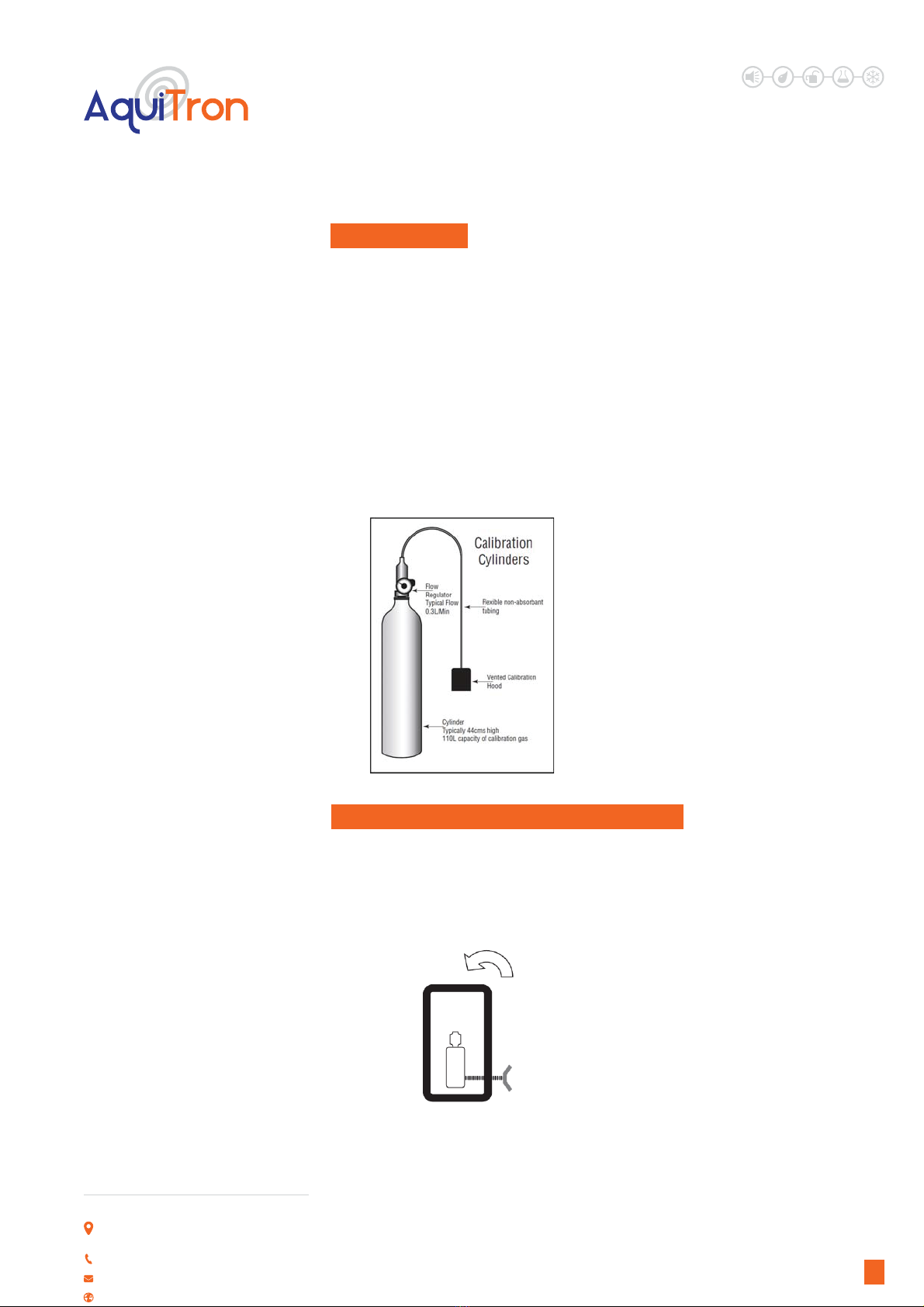
EQUIPMENT REQUIRED
• Gas cylinders with the appropriate
calibration gas concentrations
• Gas canister with zero air to calibrate /
check the Sensor Standby Voltage, required
if the sensor environment is not clean.
• Flow gas valve – rate 0.3L/min
• A voltmeter
• Estimate 30 min per sensor.
The procedure differs slightly depending on
the number of alarm levels.
ONE LEVEL SYSTEM - CALIBRATION
First disable the 3 minute alarm delay on a
one level system by moving the jumper link
at JP1 to the offposition. Two adjustments
are required and they are all performed on
the controller unit.
A. Sensor Standby Voltage (SSV)
This is the standby output for the sensor in
I. GAS CALIBRATION clean air. When gas is present around the
sensor, this voltage will increase.IF SSV is
greater than the alarm threshold voltage,
as in when a gas leak occurs, then an alarm
condition occurs - red LED, siren, relay
operates. (When JP1 is in “on” positions there
is a 3 minute delay) IF SSV falls below 0.18
V, a fault condition will be shown on the
controller - red LED, no siren, relay does not
operate. Connect a Voltmeter between Pins
4 (-Ve) & 2 (+Ve) of sensor terminal connector
block for each channel in turn (CN1, CN2 Etc.)
and adjust calibration pot (P1, P2 Etc.) to the
SSV value as per calibration label on side of
enclosure.This value should be already set
unless age or background has caused drift.
B. Alarm Threshold Voltage (ATV)
ATV is the voltage at which the alarm and
relay activate at a given gas concentration.
This voltage is normally set 3.5V. Connect a
Voltmeter (0-10 volt scale) across pins 4 & 1
of the header marked “CAL” on the controller
board.
This voltage (3.5V normal factory setting) is
set using:
1 or 2 channel system controllers - the
threshold pot “P3”
4 or 6 channel system controllers - the
threshold pot “P7”
Connect a Voltmeter between Pins 4 (-Ve)
& 2 (+Ve) of the sensor terminal connector
block for each channel in turn (CN1, CN2
Etc.) Apply calibration gas of the desired
concentration e.g. 1000 ppm in air to the
sensor and wait until the sensor output
signal stabilises, then adjust the pot that
corresponds to the channel being calibrated,
i.e. P1for channel 1, P2 for channel 2, etc.
Unit 30, Lawson Hunt Industrial Park,
Broadbridge Heath, Horsham, West Sussex,
RH12 3JR
+44 (0) 1403 216100
www.aquilar.co.uk
AT-G-DETECT
Gas Sensing System
LEAK DETECTION SOLUTIONS
6
This should be adjusted until the sensor
goes into alarm - the red LED turns on (a
voltage of approximately 3.55V). Remove the
calibration gas and allow the sensor to return
to its standby voltage. Record this voltage
reading and keep on record for subsequent
electrical set –ups. This is now calibrated for
the gas concentration used.Repeat for any
subsequent channels. Finally return jumper
JP1 to its pre calibration position.
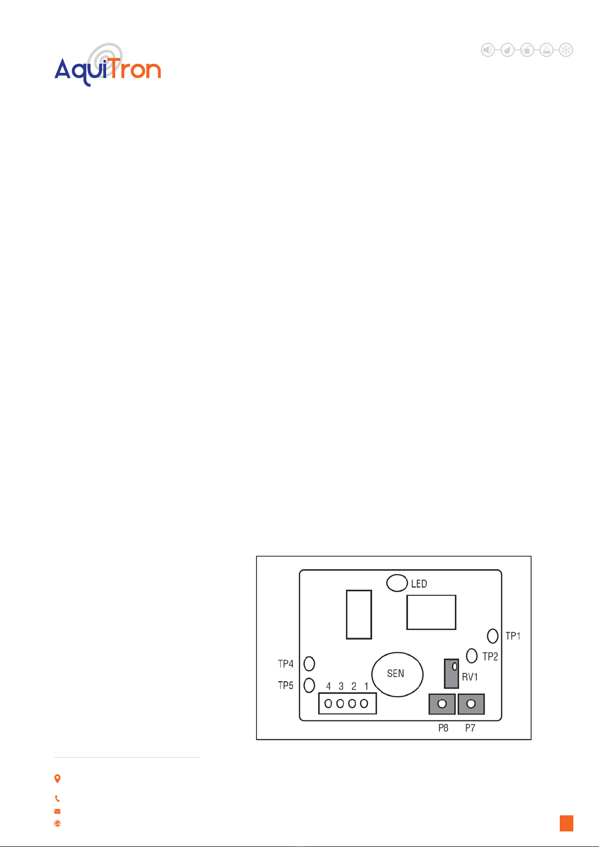
TWO LEVEL SYSTEM - CALIBRATION
The delay on a 2L system is approximately
25 seconds and cannot be deactivated. All
adjustments are performed on the sensor
PCB and there are three elements to be
adjusted: the Standby Voltage and two Alarm
Thresholds.
A. Sensor Standby Voltage (SSV)
The factory settings are shown on the
calibration label on the side of the enclosure.
Connect the voltmeter between TP5 (0V) &
TP4 (+Ve) and adjust pot RV1 for 0.3V.
This value should be already set correctly
unless age or background has caused drift.
B. Alarm Threshold Voltage (ATV)
• Low Treshhold: Connect voltmeter
between TP5 (0V) & TP2 (+Ve), set the
voltage asshown on the calibration label by
adjusting pot “P8”.
• High Threshold: Connect voltmeter
between TP5 (0V) & TP1 (+Ve), set the
voltage as shown on the calibration label by
adjusting pot “P7”.
Please remember there is an inbuilt
delay response to an alarm of approx. 25
seconds on both alarm levels
Monitor voltage between TP5 (0V) & TP4
(+Ve).Apply the low concentration calibration
gas to the sensor and wait until the sensor
output signal stabilises. Record this voltage.
Apply the high concentration calibration
gas to the sensor and wait until the sensor
output signal stabilises. Record this voltage.
If the voltages recorded for the low and high
alarms differ from the factory settings shown
on the calibration label then adjust P8 and P7
as above to the new values. Record and use
these new values for subsequent electrical
set-ups.
The High threshold voltage must be set higher than the low threshold, or the unit will not
function correctly
2 Level Sensor
Unit 30, Lawson Hunt Industrial Park,
Broadbridge Heath, Horsham, West Sussex,
RH12 3JR
+44 (0) 1403 216100
www.aquilar.co.uk

AT-G-DETECT
Gas Sensing System
LEAK DETECTION SOLUTIONS
7
J. AT-G DETECT 1 OR 2 CHANNEL UNIT
K. AT-G-DETECT 4 OR 6 CHANNEL UNIT
L. ADDITIONAL RECOMMENDATIONS
False Alarms
If false alarms are being triggered by
background gases, paint fumes, etc, or
extreme humidity or temperature conditions,
you may adjust the settings to compensate.
One Level Systems
You should reduce the SSV level in 0.5V
increments until the condition clears.
Two Level Systems
You should adjust the relevant alarm
threshold upwards in 0.2Volt increments
until the condition clears.
Unit 30, Lawson Hunt Industrial Park,
Broadbridge Heath, Horsham, West Sussex,
RH12 3JR
+44 (0) 1403 216100
www.aquilar.co.uk

AT-G-DETECT
Gas Sensing System
LEAK DETECTION SOLUTIONS
8
M. DOUBLE CHECK CONNECTIONS ARE CORRECT
To make sure the gas detectors are wired up correctly you can check the voltages at the sensor
cable terminal blocks on the controller PCB or sensor PCB using a 0-10V voltmeter as outlined
below in Table 1.
Place the negative probe on terminal position 4 and with the positive on1, 3, 2, check the Volts
values. The readings are lower at the sensor due to power drop in the line.
The terminals should have the under listed values:
Position
Number
At the sensor Controller Without sensor
fitted
4 Is the negative side of the power supply Negative Negative
1 Power Supply 7.2V minimum, unless you
have power drop reduction
+10V +12 – 15V
3 Approximately 4-5V +4.8 – 5V +5V
2 One level system – sensor standby
voltage* as shown on the calibration
label on the side of the enclosure.
Two level system – typical internal
reference values, approximately
(0=Fault)
+0.4V
+1.6V
+2.8V
0
Sensor in standby
Low Alarm Condition
High Alarm Condition
* The voltage signal from the sensor will on power up start high and gradually fall (in clean air)
to the SSV value shown on the calibration label.
You can monitor this as follows:
1 level systems: Connect a Voltmeter and monitor voltage between Pins 4 (-Ve) & 2 (+Ve) of the
sensor terminal connector block for each channel in turn (CN1,CN2 Etc.)
2 level systems: Connect voltmeter and monitor voltage between TP5 (0V) & TP4 (+Ve).
Important: All information, including illustrations, is believed to be reliable. Users, however,
should independently evaluate the suitability of each product for their application. Aquilar
Limited makes no warranty as to the accuracy or completeness of the information, and
disclaims any liability regarding its use. The only obligations of Aquilar Limited are those in
the Aquilar Standard Terms and Conditions of Sale for this product, and in no case will Aquilar
Limited be liable for any incidental, indirect, or consequential damages arising from the sale,
resale, use or misuse of the product. Specifications are subject to change without notice. In
addition, Aquilar Limited reserves the right to make changes – without notification to Buyer
– to processing or materials that do not affect compliance with any applicable specification.
AquiTron is a trademark of AquiTron Limited
Aquilar is a trademark of Aquilar Limited
V204.2019
Unit 30, Lawson Hunt Industrial Park,
Broadbridge Heath, Horsham, West Sussex,
RH12 3JR
+44 (0) 1403 216100
www.aquilar.co.uk
Table of contents
Other aquilar Gas Detector manuals

Popular Gas Detector manuals by other brands

STATUS SCIENTIFIC CONTROLS
STATUS SCIENTIFIC CONTROLS FGD10A Installation, Commissioning & Routine Gas Testing Manual

CPS
CPS GS40 instruction manual

WatchGas
WatchGas AirWatch Mk 1.0 Quick reference card

RKI Instruments
RKI Instruments GX-3R Pro Operator's manual

BEINAT
BEINAT NASE25/K Quick user guide

IGD
IGD 2-Wire Systems Installer's guide


Elliwell
Elliwell LKD 500 user manual

MSA
MSA ALTAIR 2X operating manual

Trolex
Trolex Sentro 1 TX6351 user manual

New Cosmos Electric
New Cosmos Electric KS-7D instruction manual

Quatrosense Environmental
Quatrosense Environmental QEL Installation, operation and maintenance manual

Tecnogas
Tecnogas CD-34 quick start guide