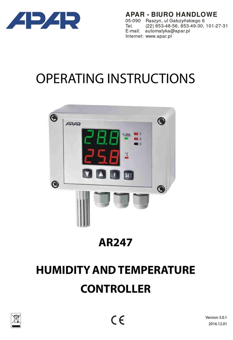
APAR AR601 User manual

User Manual
Temperature Controller
AR601
Version 3.1
2013.02.13

2
Thank you for choosing our product.
This user manual will help you with proper handling and safe
operation of the controller.
Before installation and first use please read this user manual with
understanding.
In case of additional questions please contact our technical advisor.
Table of contents
1.
SAFETY PRECAUTIONS......................................................................
3
2.
INSTALLATION INSTRUCTIONS.........................................................
3
3.
AR601 CONTROLLER GENERAL CHARACTERISTICS...........................
3
4.
TECHNICAL SPECIFICATIONS.............................................................
4
5.
IMPORTANT USAGE INFORMATION.................................................
5
6.
HOUSING AND INSTALLATION METHOD.........................................
5
7.
TERMINAL STRIPS AND ELECTRICAL CONNECTIONS DESCRIPTION.
6
8.
BUTTONS, DISPLAY AND LED DESCRIPTION.....................................
6
9.
OUTPUT SETPOINT VALUE DISPLAY AND CHANGE..........................
7
10.
CONFIGURATION PARAMETERS SETUP............................................
7
11.
MESSAGES AND ERRORS LIST...........................................................
8
12.
ON-OFF CHARACTERISTICS TYPES....................................................
9
13.
PID REGULATION...............................................................................
9
14.
PID AUTOTUNING.............................................................................
10
15.
MANUAL PID PARAMETERS SELECTION...........................................
11
16.
PID PARAMETERS CORRECTION.......................................................
11

3
1. SAFETY PRECAUTIONS
Please read user manual carefully before using this product.
To avoid damage to the device, make sure that all wires have been connected properly before
turning on the device.
Ensure proper working conditions, according to the specification of the device (supply
voltage, humidity, temperature)
To avoid electric shock, before making any modifications to wiring connections, turn off the
power applied to the device.
2. INSTALLATION INSTRUCTIONS
This device was designed to provide an adequate level of resistance to most disturbances that may
occur in industrial environments. In environments with unknown noise level it is recommended to
use the following measures to prevent any possible disturbance to the instrument:
Do not power the device from the same line which is used to power high power devices
without appropriate line filters.
Use shielded power cables, sensors and signal wires. Grounding of the shield should be single-
point and connected as close to the device as possible.
Avoid placing test (signal) leads directly next to and parallel to power lines and supply cables.
It is recommended to twist signal wires in pairs.
Resistance sensors in 3-wire connection should be connected with all wires identical.
Avoid proximity of remote controlled devices, electromagnetic meters, high power loads,
loads with phase or group power regulation and other devices that generate large impulse
disturbances.
3. AR601 CONTROLLER GENERAL CHARACTERISTICS
Universal thermoresistance measurement input Pt100 and thermocouple J, K, S
Panel case IP64 from front, IP20 from connections side
Designed for constant value regulation
1 relay regulating output or SSR output with ON-OFF characteristics with hysteresis, PID,
AUTOTUNING PID
LED digital display with brightness regulation
Relay state LED indication
Password protected access to configuration parameters
Parameters configuration by 3-key keyboard
Possibility to lock changes of preset values
Software digital filtration
High precision and resistance to disturbances that may occur in industrial environments

4
4. TECHNICAL SPECIFICATIONS
Universal input (keyboard selection), display and regulation range:
-Pt100 (3- or 2-wires).................. -100 ÷850°C (factory input setting)
-Thermocouple J......................... 0 ÷ 800°C
-Thermocouple K........................ 0 ÷ 1200°C
-Thermocouple S........................ 0 ÷ 1600°C
-Electronic temperature compensation for thermocouple cold ends
Pt100 lead resistance............................. Rd < 30Ω(3-wires, each line)
Pt100 input current................................ ~250µA
Digital reading......................................... 4 LED digits, red
-Display range.............................. -999 ÷ 9999
-Display resolution....................... 0.1°C or 1°C
-Display digits height.................... 9mm
Accuracy:
-Pt100............................................ 0.2% of measurement range ±1 digit
-Thermocouples............................. 0.3% of measurement range ±1 digit
-Thermocouple inputs additional... ±2°C (cold ends temperature)
Response time............................................ 0.5 ÷ 2s (programmed by parameter 2:
Relay outputs (P1)
-For resistance loads....................... 8A / 250Vac
-For inductive loads......................... 2A / 250Vac
-Full load durability.......................... min. 2 x 10⁵switching
SSR output................................................... 12V, transistor OC, current limiting resistance 440Ω
Signalization
-Detected errors.............................. display messages
-Relay activity.................................. 1 red LED (1)
Table housing............................................. 48 x 48 x 79mm
-Table window................................. 46 x 46mm
Sealing class................................................ IP64 –front panel, IP20 –connections
Power supply.............................................. 230Vac (85 ÷ 260Vac) / 3VA
-Low voltage ac................................ 24Vac (15 ÷ 50Vac) / 3VA
-Low voltage dc................................ 24Vdc (18 ÷ 72Vdc) / 3W
Working temperature range....................... 0 ÷ 50°C
Relative humidity range.............................. 0 ÷ 90% RH (no condensation)
Weight.......................................................... 125g
EMC............................................................... resistance: PN-EN 61000-6-2:2002(U)
emissivity: PN-EN 61000-6-4:2002(U)

5
5. IMPORTANT USAGE INFORMATION –suppression systems use
If inductive load is connected to relay contacts (i.e. contactor coil or transformer) then during its
contacts disconnection surges and electric arc often occurs. They are caused by discharge of energy
stored in the inductor. The most negative effects of these surges are: reducing the life of the
contactors and relays, destruction of semiconductors (diodes, thyristors, triacs), measurement and
control systems damage or distortion, emission of electromagnetic field that interferes local devices.
To avoid these consequences, surges have to be reduced to a safe level. The easiest way to achieve it
is to connect suitable suppression module directly to inductive load contacts. In general to each type
of inductive load suitable suppression module should be selected. Modern contactors are usually
factory equipped with suppression module. When there is no suppression module, you should buy
contactor with built in suppression module. Temporary you can shunt
the load with RC circuit, i.e. R=47Ω/1W and C=22nF/630V.
Suppression module should be connected to inductive load contacts.
Suppression circuit usage reduces relay contacts burning and reduces
probability of contacts sticking.
6. HOUSING AND INSTALLATION METHOD
Panel INCABOX............................ 48 X 48 XT L57
Front panel...................... polycarbonate, protection level IP65
Housing body................... self-extinguishing NORYL 94V-0
Housing dimensions.................... 48 x 48 x 79mm
Table window............................... 48 x 46mm
Fitting............................................ brackets on case sides

6
7. TERMINAL STRIPS AND ELECTRICAL CONNECTIONS DESCRIPTION
Connectors
Description
1-2-3
Pt100 input (2- and 3- wires)
3-4
Thermocouple input TC (J, K, S)
12-13
Power supply input 230Vac
14-15-16
P1 relay output or SSR1
8. BUTTONS, DISPLAY AND LED DESCRIPTION
Controller has 3 buttons:
-Parameter value display (marked as SET in manual)
-Preset value display and change mode enter (see section 9)
-Displayed errors deleting
or
-Move to next/previous parameter (marked as UP or DOWN in
manual)
-Displayed errors deleting
Available keys combinations:
SET + DOWN or UP - increase / decrease parameter value
DOWN + UP - fast return to measured value display (default value)
- when pressed for more than 3 seconds –entering password set mode
Display function:
-display of measured value, parameters names and values, messages and
errors
LED diode function:
- P1/SSR1 output state display (according to parameter 5 value:

7
9. OUTPUT SETPOINT VALUE DISPLAY AND CHANGE
When in measured value display mode, short press SET button to display SET1 message:
-Next press SET button to display (preview) setpoint value
-Press SET button together with UP or DOWN, to change setpoint value (if settings lock is not
turned on, parameter 17 - , see table 1, chapter 10)
-Exit setting mode: press and hold UP and DOWN buttons simultaneously for 5 seconds.
Setpoint value can be also configured in programming mode described in chapter 10.
10. CONFIGURATION PARAMETERS SETUP
During first use display can show error caused by lack of the sensor or different connected
sensor than factory programmed. In this situation you have to connect proper sensor or
change configuration parameters.
Press and hold DOWN and UP buttons simultaneously for a few seconds –display will show
symbol for a while and then with first digit blinking. Using DOWN and UP
buttons enter the password (factory default value is ), moving to next digits is possible
using SET button. Parameter 18 - (password) can be changed
After entering password correctly, each press of SET button will display message and
enter configuration parameters setup menu, where:
-Mnemonic parameter name is shown on display (i.e. ,... –table 1),
-After pressing SET button display will show this parameter value,
-DOWN button moves to the next parameter and UP button moves to the previous
parameter,
-SET button together pressed simultaneously with UP or DOWN button will change value of
current parameter,
-Exit from configuration menu by pressing UP and DOWN buttons simultaneously (or waiting
2 minutes)
In case you notice difference between displayed value and real input signal value it’s possible
to zero display and sensitivity of certain sensor –parameters 10- (zero) and 11-
(sensitivity).
Table 1. Configuration parameters
Param. name change –UP or DOWN
Param. value change –SET + UP or DOWN
Settings
N
o
Mnem
Param. Description
Param. value and range
Default
User
0
Input type
1
Filtration level (1)
2
Display resolution
3
Lower limit for
Within output measurement range
4
Upper limit for
Within output measurement range
5
Output 1 LED lights when
OFF, ON

8
6
Output 1 status out of
measurement range (3)
no changes, OFF
ON
7
Output 1 characteristics
(2)
OFF, HEATING
COOLING
8
Output 1 setpoint
Within range ÷
9
Output 1 hysteresis
10
Zero shift
11
Magnification
12
PID proportionality range
( - turn off PID action)
13
integration time constant
(PID)
s, ( - turn off integration)
s
14
derivative time constant
(PID)
s, ( - turn off differentiation)
s
15
oscillation period (PID)
s
s
16
PID autotuning type
(section 14)
OFF, manual start
start after each power on
17
values change
lock
no locks, SET1
18
Protection password (4)
19
Password protection (4)
OFF, ON
20
Display brightness
, step 10%
Cautions:
(1) –for response time is 0.5 second, for response time is about 2 seconds.
Higher filtration level means more smooth measured value and longer response time.
(2) ON-OFF characteristics information can be found in chapter 12,
(3) Parameter also defines output state for sensor circuit damage.
(4) When , parameters configuration access doesn’t require password.
11. MESSAGES AND ERRORS LIST
...
Upper display segments –upper sensor range exceeded or sensor damage
...
Lower display segments –lower sensor range exceeded or sensor damage
...
Incorrect protection password entered
...
Autotuning error, chapter 14 (error reset with any button)
...
Performing PID autotuning function
...
Configuration protection password entering mode
...
Entering parameters configuration menu

9
12. ON-OFF CHARACTERISTIC TYPES
CAUTIONS:
Parameter name
Parameter number (p. 10, table 1)
7
8
9
13. PID REGULATION
Controller works in PID mode when proportionality
range (parameter 12: ) is different than zero.
Proportionality range position relative to set value
is shown on illustrations a) and b). Influence of
integral and derivative part of PID regulation is set by
parameter 13: and 14: . Parameter 15: sets
pulsation period for output P1 or SSR1 (optional).
Output state correction is performed every 1 second.
The principle of operation for P type regulation
(proportional control) for output P1 or SSR1 is shown in
the illustration c), d). To select PID parameters suitable
for certain regulation object it’s recommended to use
automatic settings selection –autotuning (chapter 14).
Information about manual PID parameters selection
and correction can be found in chapter 15 and 16.
Illustration. Principle of operation for PID regulation:
a) Proportionality range position related to set
value for heating ( ).
b) Proportionality range position related to set value for cooling ( ).
c) Duty cycle for relay output P1 or SSR1.
d) P1 relay output or SSR1 output state (for measured value within proportionality range).

10
14. PID AUTOTUNING
Autotuning automatically selects PID parameters and consists of following stages:
Tuning start delay (about 1 minute, time for actuator power on, i.e. heating power, cooling power,
fan,...), determining object characteristic, calculating and saving in non-volatile controller memory
parameters , , and , start of regulation with new PID parameters.
To start autotuning it’s necessary to set parameter 16- correctly (see chapter 10, table 1),
where value allows for manual tuning start at any time, will start tuning always
when controller power is turned on and allows for manual start. It’s recommended to start
autotuning on object with stabilized regulated value (temperature, humidity,...). Before autotuning
start actuator power supply needs to be turned off with external switch.
To manually start/stop autotuning, please perform below actions:
-Press SET button shortly, then using UP button, go to parameter
-After pressing SET button display will show selected parameter value ( = OFF, = ON)
-Pressing SET button simultaneously with UP or DOWN button set (start), then
within 1 minute turn on object power supply using external switch, setting stops
tuning.
-Exiting from setting menu: press UP and DOWN buttons simultaneously or wait 5 seconds.
During autotuning every 5 seconds display will show message together with measured
value.
Software autotuning stop (with message displayed) can occur if proper algorithm
functioning conditions are not met:
-Difference between setpoint value and initial value is less than 40°C
-Initial value is greater than setpoint value for heating or smaller than setpoint value for
cooling,
-Maximum tuning time was exceeded (9 hours),
-Process value changes too fast or to slow
After changing threshold value or regulated object parameters (i.e. heating/cooling
power, batch weight, initial temperature,...), it’s recommended to start autotuning again.

11
15. MANUAL PID PARAMETERS CONFIGURATION
Following algorithm allows PID action parameters choice –proportionality range (parameter 12),
integration time , (13), differentiation time (14) and pulsation
period (15).
1. Set regulator to ON-OFF mode (parameter = 0),
threshold required value and =0. If overregulations are not
desirable, value should be set to lower level than required.
Regulator should be connected to measurement and regulation
circuit used.
2. Watch and note process variable changes (temperature).
Note the difference (P) between the highest and the lowest value of the first oscillation and
time (T) between second and third oscillation.
3. Set configuration parameters:
- proportionality range = P
- integration time = T [s]
- differentiation time = T/4 [s]
- pulsation period = T/8 [s]
16. PID PARAMETERS CORRECTION
Autotuning function is able to set correct PID regulation parameters for most processes, however it
may be necessary to correct them. Parameters are strongly dependent each other, so you should
change only one parameter at time and watch its influence on the process:
- oscillations near threshold –increase proportionality range , increase integration time
, decrease differentiation time ,
- slow response –decrease proportionality range , differentiation times and
integration times ,
- overregulation –increase proportionality range , differentiation times and
integration times ,
- instability -increase integration time
Table of contents
Other APAR Temperature Controllers manuals
Popular Temperature Controllers manuals by other brands

Lux Elements
Lux Elements CONCEPT-BA-EH ZA Mounting and operating instructions

NEIL
NEIL PREMIUM 700 Use and installation manual

Dimplex
Dimplex RTW 401 UN quick guide

Heatmiser
Heatmiser NeoStat-hw user guide

Tunstall
Tunstall Ambient Temperature Sensor installation guide

HiTECH Technologies
HiTECH Technologies TC-136 operating manual

Danfoss
Danfoss ECL Comfort 110 quick guide

THERMOSALD
THERMOSALD UPSCR10030-M-V3 Maintenance & Operation Manual

Nibe
Nibe ECS 40 Installer manual

Metra Electronics
Metra Electronics 99-5716 Installation instruction

Fogco
Fogco Desert Fog Revolution 93800 user manual

Ropex
Ropex Resistron RES-407 operating instructions