APARIAN A-MBR User manual

Modbus Router /
Modbus Router 485
User Manual
A-MBR / A-MBR-485
Document No. D106-009
12/2017
Revision 1.15

Document No. D106-009 Page 2 of 76
Revision 1.15
CONTENTS
1. Preface ............................................................................................................................... 5
1.1. Introduction to the Modbus Router ........................................................................... 5
1.2. Features ....................................................................................................................... 5
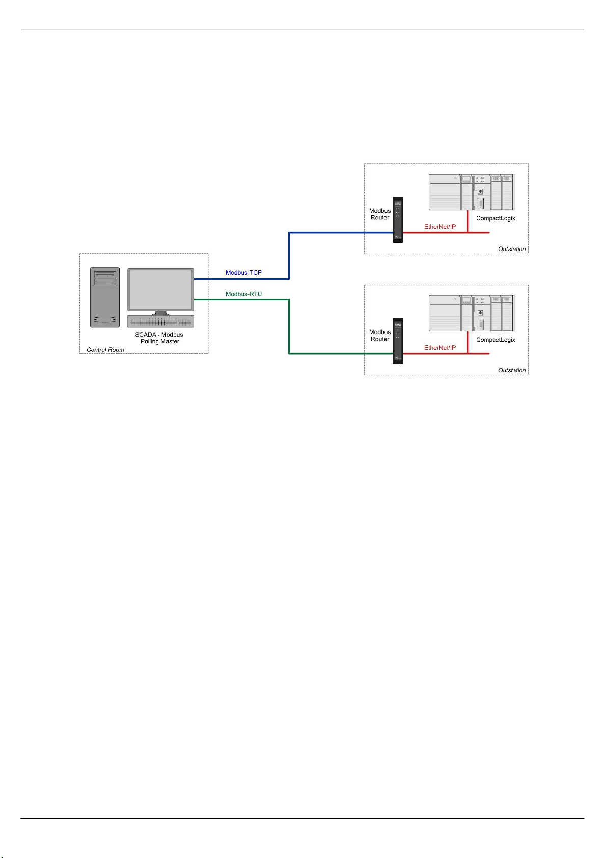
1.3. Architecture ................................................................................................................. 7
1.4. Additional Information ................................................................................................ 9
1.5. Support ........................................................................................................................ 9
2. Installation ....................................................................................................................... 10
2.1. Module Layout .......................................................................................................... 10
2.2. Module Mounting ..................................................................................................... 13
2.3. Power ........................................................................................................................ 14
2.4. RS232 Port ................................................................................................................. 14
2.5. RS485 Port ................................................................................................................. 15
2.6. RS485 Termination .................................................................................................... 15
2.7. Ethernet Port ............................................................................................................. 16
3. Setup ................................................................................................................................ 17
3.1. Install Configuration Software .................................................................................. 17
3.2. Network Parameters ................................................................................................. 17
3.3. Creating a New Project .............................................................................................. 22
3.4. Modbus parameters .................................................................................................. 24
3.5. Message Routing ....................................................................................................... 27
3.5.1. Reactive Tag Mode............................................................................................. 27
3.5.2. Scheduled Tag Mode.......................................................................................... 34
3.5.3. Unscheduled Mode ............................................................................................ 39
3.6. Module Download ..................................................................................................... 40
3.7. RSLogix 5000 Configuration ...................................................................................... 42
3.7.1. Studio 5000 Configuration (Version 20+) .......................................................... 42
3.7.2. RSLogix 5000 Configuration (Pre-Version 20) .................................................... 46
4. Operation ......................................................................................................................... 50
4.1. Message Routing ....................................................................................................... 50
4.2. RSLogix 5000 assemblies ........................................................................................... 50
1.1.1. Input Assembly................................................................................................... 51

Document No. D106-009 Page 3 of 76
Revision 1.15
1.1.2. Output Assembly................................................................................................ 52
4.3. Unscheduled Messaging ........................................................................................... 53
4.3.1. Example .............................................................................................................. 57
5. Diagnostics ....................................................................................................................... 59
5.1. LEDs ........................................................................................................................... 59
5.2. Module Status Monitoring in Slate ........................................................................... 60
5.3. Modbus Diagnostics .................................................................................................. 65
5.4. Modbus Packet Capture ............................................................................................ 66
5.5. Module Event Log...................................................................................................... 69
5.6. Web Server ................................................................................................................ 70
6. Technical Specifications ................................................................................................... 71
6.1. Dimensions ................................................................................................................ 71
6.2. Electrical .................................................................................................................... 72
6.3. Ethernet ..................................................................................................................... 72
6.4. Serial Port (RS232) ..................................................................................................... 73
6.5. Serial Port (RS485) ..................................................................................................... 73
6.6. Modbus ..................................................................................................................... 73
6.7. Certifications ............................................................................................................. 74
Index ......................................................................................................................................... 75

Document No. D106-009 Page 4 of 76
Revision 1.15
Revision History
Revision Date Comment
1.0 24 June 2015 Initial document
1.1 24 July 2015 Indication of serial data and stop bits supported
1.2 25 August 2015 Add UL Listed mark
1.3 7 September 2015 Added documentation for the RS485 version
1.4 28 September 2015 Added section for Base Address selection
1.5 30 September 2015 Add support for EtherNet/IP retry statistics and configuration
1.6 14 March 2016 Update warning on Logix Boolean 32-bit alignment to be for single and
multiple Coil/Discrete Register updates.
1.7 13 May 2016 Add ODVA Conformance mark
1.8 26 June 2016 Updated temperature range
1.9 8 August 2016
Added EDS Add-On-Profile
Added Modbus Diagnostic functions
Added RoHS2 compliant to certifications
1.10 23 May 2017 Add support for two additional interface modes.
Add RCM Conformance mark.
1.11 5 October 2017 Add UL Class 1 Division 2
1.12 6 October 2017 Update max mapping count from 20 to 40
1.13 23 October 17 Removed max Modbus writing in specification
1.14 22 November 17 Added support for multiple node emulation in Reactive Mode.
1.15 12 December 17 Added support for SLC/MicroLogix controllers.

Preface
Document No. D106-009 Page 5 of 76
Revision 1.15
1. PREFACE
1.1. INTRODUCTION TO THE MODBUS ROUTER
This manual describes the installation, operation, and diagnostics of the Aparian Modbus
Router. The Modbus Router provides intelligent data routing between EtherNet/IP and
Modbus (serial Modbus-RTU or Ethernet Modbus-TCP). NOTE: The Modbus Router 485 can
communicate on serial RS485 whilst the Modbus Router can communicate on serial RS232.
The Modbus Router allows the user to integrate Modbus devices into a Rockwell Logix
platform (e.g. ControlLogix, CompactLogix, MicroLogix, etc.) with minimal effort.
Figure 1.1. – Typical Setup
1.2. FEATURES
The Modbus Router is able to transfer data from various Modbus devices to a maximum of
three Logix controllers. The module operates in one of three modes, simplifying the
configuration for all applications.
Mode Description Message Initiator
Reactive Tag The Modbus Router will convert Modbus messages to Logix
controller tag reads or tag writes. (Modbus Slave) Remote Device

Preface
Document No. D106-009 Page 6 of 76
Revision 1.15
Scheduled Tag The Modbus Router transfers data between a Modbus device and a
number of Logix tags, using a preconfigured scheduled.
(Modbus Master)
No Logix or remote device configuration is required.
Modbus Router
Unscheduled The Modbus Router transfers messages received from a Logix
Message Instruction.
(Modbus Master)
Logix (Msg)
Table 1.1. – Modes of Operation
The Modbus Router is configured using the Aparian Slate application. This program can be
downloaded from www.aparian.com free of charge. Slate offers various configuration
methods, including a controller tag browser.
Hereafter the Modbus Router will be referred to as the module.
The module can operate in both a Logix “owned” and standalone mode. With a Logix
connection the input and output assemblies will provide additional diagnostics information
which will be available in the Logix controller environment.
The Modbus Router allows the user to integrate Modbus devices into a Logix system with
minimal effort. No copying or mapping of data in the Logix controller is required as the
Modbus Router writes directly into Logix tags.
The module also provides a range of statistics and traffic analyser to help fault find any
problems.
The Modbus Router supports Modbus on two ports which can be configured from the Slate
environment; Modbus-RTU (Serial) or Modbus-TCP (Ethernet).
The Modbus Router (RS232 version) uses isolated RS232 for Modbus serial communication
providing better noise immunity. The RS232 or RS485 port uses a terminal block for
convenient installation.
A built-in webserver provides detailed diagnostics of system configuration and operation,
including the display of Modbus operation and communication statistics, without the need for
any additional software.

Preface
Document No. D106-009 Page 7 of 76
Revision 1.15
1.3. ARCHITECTURE
The figure below provides an example of the typical network setup in reactive mode, where
the Modbus Router acts as a Modbus slave device.
Figure 1.2. - Example of a typical network setup in reactive mode
By converting and redirecting serial Modbus messages from legacy devices to EtherNet/IP,
the module provides an interface for data exchange to Allen-Bradley ControlLogix and
CompactLogix platforms. This enables user to replace legacy devices and systems with
minimal effort and downtime.
The Modbus Router allows a Logix platform to seamlessly integrate into a Modbus network
with Reactive Tag Mode. The module will route Modbus message directly to Logix tags with
no need for additional ladder code.

Preface
Document No. D106-009 Page 8 of 76
Revision 1.15
Figure 1.3. - Example of a typical network setup in scheduled/unscheduled mode
Systems that rely on a central ControlLogix communicating to a number of remote Modbus
devices, (e.g. Electrical Protection Units or Remote Terminal Units), may find the Modbus
Router useful when operating in Scheduled Tag Mode as shown in the figure above. The
module, acting as a Modbus master, will exchange data between the Modbus device and Logix
platform at a configured interval without any need for additional coding or mapping.

Preface
Document No. D106-009 Page 9 of 76
Revision 1.15
1.4. ADDITIONAL INFORMATION
The following documents contain additional information that can assist the user with the
module installation and operation.
Resource Link
Slate Installation http://www.aparian.com/software/slate
Modbus Router User Manual
Modbus Router Datasheet
Example Code & UDTs
http://www.aparian.com/products/modbusrouter
Ethernet wiring standard www.cisco.com/c/en/us/td/docs/video/cds/cde/cde205_220_420/installation/guide/
cde205_220_420_hig/Connectors.html
CIP Routing The CIP Networks Library, Volume 1, Appendix C:Data Management
Modbus http://www.modbus.org
Table 1.2. - Additional Information
1.5. SUPPORT
Technical support is provided via the Web (in the form of user manuals, FAQ, datasheets etc.)
to assist with installation, operation, and diagnostics.
For additional support the user can use either of the following:
Resource Link
Contact Us web link www.aparian.com/contact-us
Support email support@aparian.com
Table 1.3. – Support Details

Installation
Document No. D106-009 Page 10 of 76
Revision 1.15
2. INSTALLATION
2.1. MODULE LAYOUT
The module has three ports at the bottom of the enclosure as shown in the figure below. The
ports are used for Ethernet, RS232 or RS485 serial, and power. The power port uses a three-
way connector which is used for the DC power supply positive and negative (or ground)
voltage as well as the earth connection.
The Ethernet cable must be wired according to industry standards which can be found in the
additional information section of this document.
When using the RS232 version the RS232 port uses a four way connector. This provides
connection for the communication transmit (TX), receive (RX), and ground (GND) conductors.
The fourth connection (earth) is used for shielding the cable in high noise environments.
Figure 2.1. – Modbus Router (RS232) side and bottom view
When using the RS485 version the RS485 port uses a four way connector. This provides
connection for the communication positive (+) and negative (-) conductors (the third
connector is N/A). The fourth connection (earth) is used for shielding the cable in high noise
environments.

Installation
Document No. D106-009 Page 11 of 76
Revision 1.15
Figure 2.2 – Modbus Router (RS485) side and bottom view
The module provides three diagnostic LEDs as shown in the front view figure below. These
LEDs are used to provide information regarding the module system operation, the Ethernet
interface, and the auxiliary communication interface (RS232 or RS485).
Figure 2.3. – Modbus Router front and top view
The module provides four DIP switches at the top of the enclosure as shown in the top view
figure above.

Installation
Document No. D106-009 Page 12 of 76
Revision 1.15
DIP Switch Description
DIP Switch 1 Used to force the module into “Safe Mode”. When in “Safe Mode” the module will not
load the application firmware and will wait for new firmware to be downloaded. This
should only be used in the rare occasion when a firmware update was interrupted at
a critical stage.
DIP Switch 2 This will force the module into DHCP mode which is useful when the user has forgotten
the IP address of the module.
DIP Switch 3 Reserved
DIP Switch 4 Reserved
Table 2.1. - DIP Switch Settings

Installation
Document No. D106-009 Page 13 of 76
Revision 1.15
2.2. MODULE MOUNTING
The module provides a DIN rail clip to mount onto a 35mm DIN rail.
Figure 2.4 - DIN rail specification
The DIN rail clip is mounted on the bottom of the module at the back as shown in the figure
below. Use a flat screw driver to pull the clip downward. This will enable the user to mount
the module onto the DIN rail. Once the module is mounted onto the DIN rail the clip must be
pushed upwards to lock the module onto the DIN rail.
Figure 2.5 - DIN rail mouting

Installation
Document No. D106-009 Page 14 of 76
Revision 1.15
2.3. POWER
A three-way power connector is used to connect Power+, Power– (GND), and earth. The
module requires an input voltage of 10 – 28Vdc. Refer to the technical specifications section
in this document.
Figure 2.6 - Power connector
2.4. RS232 PORT
NOTE: The RS232 port is only applicable with the RS232 version of the Modbus
Router (catalog A-MBR).
The four-way RS232 connector is used to connect the transmit (TX), receive (RX), and GND
conductors for serial communication. The shield terminal can be used for shielded cable in
high noise environments.
NOTE: The shield of the RS232 port is internally connected to the power
connector earth. Thus, when using a shield it is important to connect the Earth
terminal on the power connector to a clean earth. Failing to do this can lower
the signal quality of the RS232 communication.
NOTE: When using a shielded cable, it is important that only one end of the
shield is connected to earth to avoid current loops. It is recommended to
connect the shield to the Modbus Router module, and not to the other
Modbus device.
Figure 2.7 - RS232 connector

Installation
Document No. D106-009 Page 15 of 76
Revision 1.15
2.5. RS485 PORT
NOTE: The RS485 port is only applicable with the RS485 version of the Modbus
Router (catalog A-MBR-485).
Figure 2.8 – RS485 connector
The four-way RS485 connector is used to connect the positive (+) and negative (-)
communication conductors for serial communication. The shield terminal can be used for
shielded cable in high noise environments.
NOTE: The shield of the RS485 port is internally connected to the power
connector earth. Thus, when using a shield it is important to connect the Earth
terminal on the power connector to a clean earth. Failing to do this can lower
the signal quality of the RS485 communication.
NOTE: When using a shielded cable, it is important that only one end of the
shield is connected to earth to avoid current loops. It is recommended to
connect the shield to the Modbus Router module, and not to the other
Modbus device.
2.6. RS485 TERMINATION
NOTE: The RS485 port is only applicable with the RS485 version of the Modbus
Router (catalog A-MBR-485).
All RS485 networks need to be terminated at the extremities (start and end point) of the
communication conductor. The termination is done by placing a resistor between the positive
and negative communication conductor. The value of the resistor will depend on the
characteristic impedance of the cable chosen, but generally ranges from 100 Ohm to 150
Ohm.

Installation
Document No. D106-009 Page 16 of 76
Revision 1.15
2.7. ETHERNET PORT
The Ethernet connector should be wired according to industry standards. Refer to the
additional information section in this document for further details.

Setup
Document No. D106-009 Page 17 of 76
Revision 1.15
3. SETUP
3.1. INSTALL CONFIGURATION SOFTWARE
All the network setup and configuration of the module is achieved by means of the Aparian
Slate device configuration environment. This software can be downloaded from
http://www.aparian.com/software/slate.
Figure 3.1. - Aparian Slate Environment
3.2. NETWORK PARAMETERS
The module will have DHCP (Dynamic Host Configuration Protocol) enabled as factory default.
Thus a DHCP server must be used to provide the module with the required network
parameters (IP address, subnet mask, etc.). There are a number of DHCP utilities available,
however it is recommended that the DHCP server in Slate be used.
Within the Slate environment, the DHCP server can be found under the Tools menu.
Figure 3.2. - Selecting DHCP Server
Once opened, the DHCP server will listen on all available network adapters for DHCP requests
and display their corresponding MAC addresses.

Setup
Document No. D106-009 Page 18 of 76
Revision 1.15
Figure 3.3. - DHCP Server
NOTE: If the DHCP requests are not displayed in the DHCP Server it may be due
to the local PC’s firewall. During installation the necessary firewall rules are
automatically created for the Windows firewall. Another possibility is that
another DHCP Server is operational on the network and it has assigned the IP
address.
To assign an IP address, click on the corresponding “Assign” button. The IP Address
Assignment window will open.
Figure 3.4. - Assigning IP Address
The required IP address can then be either entered, or a recently used IP address can be
selected by clicking on an item in the Recent List.
If the “Enable Static” checkbox is checked, then the IP address will be set to static after the IP
assignment, thereby disabling future DHCP requests.
Once the IP address window has been accepted, the DHCP server will automatically assign the
IP address to the module and then read the Identity object Product name from the device.

Setup
Document No. D106-009 Page 19 of 76
Revision 1.15
The successful assignment of the IP address by the device is indicated by the green
background of the associated row.
Figure 3.5. - Successful IP address assignment
It is possible to force the module back into DHCP mode by powering up the device with DIP
switch 2 set to the On position.
A new IP address can then be assigned by repeating the previous steps.
NOTE: It is important to return DIP switch 2 back to Off position, to avoid the
module returning to a DHCP mode after the power is cycled again.
If the module’s DIP switch 2 is in the On position during the address assignment, the user will
be warned by the following message.
Figure 3.6. - Force DHCP warning
In addition to the setting the IP address, a number of other network parameters can be set
during the DHCP process. These settings can be viewed and edited in Slate’s Application
Settings, in the DHCP Server tab.
Once the DHCP process has been completed, the network settings can be set using the
Ethernet Port Configuration via the Target Browser.
The Target Browser can be accessed under the Tools menu.

Setup
Document No. D106-009 Page 20 of 76
Revision 1.15
Figure 3.7. - Selecting the Target Browser
The Target Browser automatically scans the Ethernet network for EtherNet/IP devices.
Figure 3.8. - Target Browser
Right-clicking on a device, reveals the context menu, including the Port Configuration option.
Figure 3.9. - Selecting Port Configuration
This manual suits for next models
1
Table of contents
Other APARIAN Network Router manuals