manuals.online logo
Brands
  1. Home
  2. •
  3. Brands
  4. •
  5. Apator
  6. •
  7. Switch
  8. •
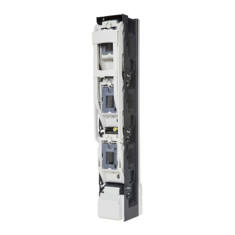
  9. Apator ARS 3f User manual

Apator ARS 3f User manual

Apator S.A., 87-100 Toruń, ul. Gdańska 4a lok. C4
tel.: +48 56 61 91 244, fax: +48 56 61 91 295
www.apator.com
Zakład produkcyjny Manufacturing area
Ostaszewo 57C, 87-148 Łysomice
ARS 3f;
ARS 400, ARS 2 pro, ARS 3 pro, ARS 630kVA pro, RWS 1250 pro
Listwowe rozłączniki izolacyjne
Vertical fuse switch disconnectors
Instrukcja obsługi i montażu
Mounting and operation manual
ISO 9001 PN-N-18001 ISO 14001
- 3 -
1.WYJĘCIEPOKRYWROZŁĄCZNIKA
TAKINGOFFTHECOVEROFTHEDISCONNECTOR
a) chwycić za rączkę (Fot. 1) i przemieścić ją do pozycji aż rączka zablokuje się o zwalniacz (Fot. 2)
take the handle (Fig. 1) and move it to the position of release until the handle is blocked (Fig. 2)
b) chwycić za „uszy” pokrywki (Fot. 3) i lekko wysunąć ją zgodnie z kierunkiem strzałki oznaczonej
„I”(Fot. 3). Wysuniętą pokrywkę obrócić zgodnie z kierunkiem strzałki oznaczonej „II” (Fot. 3) aż
poczuje się opór. Następnie wyciągnąć pokrywkę z napędu (Fot. 4)
take the „ears” of the cover (Fig. 3) and gently pull out it in accordance with the direction indicated
by the arrow marked „I” (Fig. 3). Rotate pulled out cover in direction indicated by the arrow
marked„II” (Fig. 3) until resistance. Next take out the cover from the operating mechanism (Fig. 4)
c) przemieścić rączkę do pozycji „pracy/załączenia” rozłącznika (Fot. 5)
move the handle to „operation/switched on” position of the disconnector (Fig. 5)
Fot. 1
Fot. 3
Fot. 2
Fot. 4
Fot. 5
I
II
zwalniacz
release
- 4 -
2.OTWORZENIEPŁYTEKMASKUJĄCYCHŚRUBYMOCUJĄCEZAMOCOWANIE
ROZŁĄCZNIKA ARS DO SZYN ZBIORCZYCH. ZAMKNIĘCIE PŁYTEK
MASKUJĄCYCHŚRUBYMOCUJĄCE
 OPENING THE MASKING PLATES FOR FIXING BOLTS. FIXING ARS TYPE
DISCONNECTOR TO BUS BARS. CLOSING THE MASKING PLATES FOR
FIXINGBOLTS
a) otworzyć płytki maskujące śruby mocujące (Fot. 6)
open masking plates for fixing bolts (Fig. 6)
b) przyłożyć podstawę rozłącznika do szyn zbiorczych o rozstawie 185mm (Fot.7 ), wkręcić śrubę
w środkowym biegunie (Fot. 8) a następnie wkręcić śruby w pozostałych biegunach.
Po zamocowaniu rozłącznika do szyn zbiorczych zamknąć płytki maskujące (Fot. 9)
Put the base of disconnector against bus bars with spacing of 185 mm (Fig.7), screw the bolt in the
middle pole (Fig. 8) and next screw the bolts in other poles. After the disconnector is fixed to bus
bars close masking plates (Fig. 9)
3.ZDJĘCIEOSŁONYZACISKÓWIPRZYMOCOWANIEPRZEWODÓW
ODPŁYWOWYCH
TAKINGOFFTHESHIELDFORTERMINALSANDFIXINGOUTPUTCABLES
a) zdjąć osłonę zacisków (Fot. 10) i dokręcić przewody odpływowe (Fot. 11– przykład dla dokręcenia
przewodu sektorowego)
Take off the shield for terminals (Fig. 10) and tighten output cables (Fig. 11– example of tightening
of sector shape cable)
Fot. 6
Fot. 7 Fot. 8 Fot. 9
- 5 -
b) założyć osłonę zacisków (Fot. 12)
mount the shield for terminals (Fig. 12)
4.ZAKŁADANIEDODATKOWEGOELEMENTUOPISOWEGOWOSŁONIE
ZACISKÓW
MOUNTINGOFEXTRALABELINTHESHIELDFORTERMINALS
a) wsunąć dodatkowy element opisowy od spodu osłony zacisków (Fot. 13)
insert extra label from the bottom of the shield for terminals (Fig. 13)
Fot. 12
Fot. 13
Fot. 10 Fot. 11
- 6 -
5.MONTOWANIEIDEMONTOWANIEWKŁADEKTOPIKOWYCHLUB
ZWIERACZYNOŻOWYCHWPOKRYWIE
MOUNTINGANDDISMANTLINGOFTHEFUSELINKSORSOLIDLINKSIN
THECOVER
a) umieścić wkładkę topikową lub zwieracz nożowy w zaczepach pokrywy (Fot. 14 - ARS 2 pro, ARS
3 pro, ARS 630KVA. Fot. 14a - ARS 400A).
place the fuse link or solid link in catches of the cover (Fig. 14 - ARS 2 pro, ARS 3 pro, ARS 630KVA.
Fig. 14a - ARS 400A).
b) trzymając pokrywę wcisnąć palcem wskazującym wystający element suwaka, następnie wysunąć
wkładkę topikową lub zwieracz nożowy z zaczepów pokrywy (Fot. 15 - ARS 2 pro, ARS 3 pro, ARS
630KVA) Chwycić i wysunąć zimną wkładkę topikową lub zwieracz nożowy z zaczepów pokrywy
(Fot 15a - ARS 400A) .
holding the cover in hand push in outstanding element of the slide by an index finger and then pull
out the fuse link from catches of the cover (Fot. 15 - ARS 2 pro, ARS 3 pro, ARS 630KVA). Grab and
pull out cold fuse link or solid link from catches of the cover (Fig. 15a - ARS 400A).
6.UMIESZCZANIEPOKRYWYZZAMONTOWANYMIWKŁADKAMI
TOPIKOWYMILUBZWIERACZAMINOŻOWYMIWROZŁĄCZNIKU
MOUNTINGTHECOVERWITHFUSELINKSORSOLIDLINKSINTHE
DISCONNECTOR
a) wykonać operację zgodnie z punktem 1a) dla rozłącznika zawieszonego na moście szynowym
make the operation according to point 1a) for the disconnector mounted on bus bar bridge
Fot. 14 Fot. 14a
Fot. 15 Fot. 15a
- 7 -
Fot. 16
I
II
b) chwycić za „uszy” pokrywki i osadzić ją w prowadniku (aż do oporu) zgodnie z kierunkiem strzałki oznaczonej
jako „I” (Fot. 16). Wsuniętą pokrywkę obrócić zgodnie z kierunkiem strzałki oznaczonej jako „II” (Fot. 16)
take „ears” of the cover and set it in a guide (up to resistance) in direction indicated by the arrow
marked „I” (Fig. 16). Inserted cover rotate in accordance with the arrow marked as „II” (Fig. 16)
c) zatrzasnąć pokrywkę w prowadniku (Fot. 17)
snap the cover in the guide (Fig. 17)
d) powyższe operacje wykonać dla kolejnych pokryw
above operations one should make for the following covers
7.ZAŁĄCZANIEAPARATU
SWITCHINGONTHEDISCONNECTOR
a) chwycić rączkę i energicznym ruchem przesunąć ją w kierunku jak wskazuje strzałka (Fot. 18)
aż do całkowitego zamknięcia rozłącznika (Fot. 19)
take the handle and firmly move it in direction indicated by the arrow (Fig. 18) until the disconnector
is completely closed. (Fig. 19)
Fot. 18 Fot. 19
Fot. 17
- 8 -
Fot. 22
8.ROZŁĄCZANIENIEAPARATU
SWITCHINGOFFTHEDISCONNECTOR
a) chwycić za rączkę rozłącznika i energicznym ruchem wykonać ruch rączką w kierunku jak to
wskazuje strzałka (Fot. 20) aż do momentu zablokowania się rączki o zwalniacz (Fot. 21)
take the handle of the disconnector and move it firmly in direction indicated by the arrow (Fig. 20)
to the position of the release until the handle is blocked (Fig. 21)
9.PARKOWANIEAPARATU
PARKINGOFTHEDISCONNECTOR
a) rozłączyć rozłącznik zgodnie z punktem 8
switch off the disconnector according to the point 8
b) nacisnąć zwalniacze aż do momentu zwolnienia (Fot. 22)
press the releases until the handle is released (Fig. 22)
c) przy naciśniętych zwalniaczach pociągnąć za rączkę aż do oporu (Fot. 23)
while the releases are pressed pull the handle until resistance (Fig. 23)
Fot. 23
Fot. 21 Fot. 20
- 9 -
Fot. 26
Fot. 24 Fot. 25
Fot. 27
d) chwycić za napęd rozłącznika, pociągnąć do siebie (Fot. 24), następnie trzymając za rączkę prze-
mieścić ją tak jak na rysunku (Fot.25).
take an operating mechanism of the disconnector and pull it (Fig. 24), and then holding the handle
move it as it has been shown in (Fig.25).
e) wsunąć napęd w obudowie aż poczuje się opór (Fot. 26). W ten sposób otrzymujemy stan parko-
wania rozłącznika
insert the operating mechanism in the cabinet until resistance (Fig. 26). In this manner we get
parking of the disconnector
10.ZWOLNIENIESTANUPARKOWANIAAPARATU
RELEASINGTHEPARKINGOFTHEDISCONNECTOR
a) chwycić za rączkę i przemieścić ją zgodnie z kierunkiem strzałki aż do oporu (Fot. 27).
take the handle and move it in direction indicated by the arrow until resistance (Fig. 27).
- 10 -
Fot. 29 Fot. 30
b) nacisnąć zwalniacze aż do momentu zwolnienia rączki i pociągnąc za rączkę aż do oporu (Fot. 28)
press the releases until the handle is released and pull the handle until resistance (Fig. 28)
c) w takiej pozycji wepchnąć napęd w obudowie aż poczuje się opór (Fot. 29) i zamknąć rozłącznik (Fot. 30)
in this position insert operating mechanism in the cabinet until resistance (Fig. 29) and then close
the disconnector (Fig. 30)
11.WYJMOWANIENAPĘDUWCELUMONTAŻUUZIEMIACZAIUZIEMIANIE
ROZŁĄCZNIKA(dlaARS400,ARS2pro,ARS3pro)
  TAKINGOUTTHEOPERATINGMECHANISMINORDERTOMOUNTTHE
GROUNDINGSWITCHANDPROVISIONWITHGROUNDINGOFTHE
DISCONNECTOR(forARS400,ARS2pro,ARS3pro)
a) postępować zgodnie z punktem 9 a, b, c, d, następnie wyjąć napęd (Fot. 31)
proceed in accordance with the point 9a,b,c,d, and next take out the operating mechanism (Fig 31)
b) zamontować zacisk uziemiacza do szyny PN (Fot. 32), używając drążka izolacyjnego, uziemić roz-
łącznik od strony odbioru za pomocą wkładek zwierających postępując (dla każdej fazy) wg Fot.
33, 34, 35
Fot. 31
Fot. 28
- 11 -
mount the clamp of the earthing switch on the PN bus bar (Fig. 32), using the insulating pole,
ground the disconnector from loaded side by use of solid links proceeding (for each phase) in
accordance with Fig. 33, 34, 35
12.DEMONTAŻUZIEMIACZAIMONTOWANIENAPĘDUROZŁĄCZNIKA(dla
ARS400,ARS2pro,ARS3pro)
DISMANTLINGOFEARTHINGSWITCHANDMOUNTINGOFOPERATING
SWITCHOFTHEDISCONNECTOR(forARS400,ARS2pro,ARS3pro)
a) postępując w odwrotnej kolejności do podanej w punkcie 11 b zdemontować uziemiacz
dismantle the earthing switch proceeding in reverse order presented in point 11 b
b) wsunąć napęd do obudowy aż poczuje się opór (Fot. 36). Należy zwrócić szczególną uwagę na
prawidłowe wprowadzenie prowadnicy lewej i prawej w obudowę (Fot. 36a, Fot. 36b). Następnie
zamknąć aparat zgodnie z punktem 10 a, b, c.
insert the operating mechanism into cabinet until resistance (Fig. 36). One should pay particular
attention to correct insertion of the left and right guidelines into cabinet (Fig. 36a, Fig. 36b). Next
close the disconnector according to point 10 a, b, c.
Fot. 36
Fot. 36a
Fot. 36b
Fot. 32 Fot. 33
Fot. 34 Fot. 35
- 12 -
Fot. 39
13.PRZYŁĄCZENIEPRZEWODÓWODPŁYWOWYCHODGÓRY
CONNECTIONOFOUTLETCABLESFROMTHETOP
CZYNNOŚĆ TĘ NALEŻY WYKONAĆ PRZED MONTAŻEM ROZŁĄCZNIKA DO SZYN ZBIORCZYCH
THE ACTION SHOULD BE PERFORMED BEFORE THE DISCONNECTOR IS MOUNTED ON BUS BARS
a) wyjąć pokrywki z rozłącznika zgodnie z punktem 1 lecz nie opuszczać rączki (Fot. 37) oraz zdjąć
osłonę zacisków (Fot. 38)
take out the plates from the disconnector in accordance with the point 1 but do not lower a handle
(Fig. 37) and then take off the shield for terminals (Fig. 38)
b) wkrętakiem przekręcić zgodnie wskazówek ruchem wskazówek zegara 6 śrub w obudowie o kąt 90
stopni (Fot. 39)
Turn clockwise 6 bolts by the angle of 90º using a screwdriver (Fig. 39)
c) wyjąć obudowę z podstawy (Fot. 40)
take the cabinet out of the base (Fig. 40)
Fot. 40
Fot. 37 Fot. 38
- 13 -
d) po zdjęciu obudowy obrócić ją względem podstawy o kąt 180 stopni (Fot. 41) i ponownie umieścić
ją na podstawie (Fot. 42) zwracając uwagę aby śruby znalazły się w otworach (Fot. 43) a następnie
wkrętakiem przekręcić każdą śrubę przeciwnie do ruchu wskazówek zegara o kąt 90 stopni (Fot. 44)
after the cabinet is taken out, turn it versus to the base by 180º (Fig. 41) and set it again on the base
(Fig. 42) paying attention to bolts to be in the holes (Fig. 43) and then turn anticlockwise each bolt
by the angle of 90º using a screwdriver (Fig. 44)
e) w ten sposób uzyskaliśmy rozłącznik gotowy do montażu na moście szynowym z odpływami
od góry, a jego podłączenie wykonać zgodnie z punktami 2-6.
this manner we have obtained the disconnector ready to be mounted on bus bar bridge with the
outlets from the top and its connection should be carried out in accordance with points 2-6.
Fot. 43 Fot. 44
Fot. 41 Fot. 42
- 14 -
Dane techniczne
Technical data ARS 400A ARS 2 pro ARS 3 pro ARS
630kVA pro
RWS
1250 pro
Kategoria użytkowania przy
Utilization category at -Ue=690V~
AC-22B
Ue=690V~ AC-22B
Ue=400V~ AC-23B
Ue=690V~ AC-21B
Ue=500V~ AC-22B
Ue=400V~ AC-23B
Ue=400V~
AC-22B
Ue=400V~
AC-22B
Znam. prąd cieplny Ith
Rated thermal current A400 400 / 600* 630 / 750* 910 1250
Napięcie znam. Un
Rated voltage V690 690 690 400 400
Znam. napięcie izolacji Ui
Rated insulated voltage V 1000 1000 1000 1000 1000
Znam. napięcie udarowe wytrz. Uimp
Rated impulse withstand voltage kV 12 12 12 12 12
Znam. prąd zwar. umowny załączalny
Rated short circuit making capacity kA 100 100 100 50 -
Znam. prąd zwar. umowny wytrz.
Rated short-time withstand current kA 100 100 100 50 -
Prąd znam. załączalny zwarciowy Icm
Rated short-circuit making capacity kA -15 16 -15
Prąd krótkotrwały wytrzymywany Icw
Short-time withstand current kA -15 16 -15
Częstotliwość znam.
Rated frequency Hz 50-60 50-60 50-60 50-60 50-60
Stopień ochrony
Protection degree IP 30 30 30 30 30
Trwałość mechaniczna
Mechanical durability -1600 1000 1000 600 600
Trwałość elektr.
Electrical durability -200 200 200 100 100
Wielkość wkładek topikowych
Size of fuse links -1 ( do 250A)
i 2 (do 400A) 23gTr (630kVA) zwieracze nożowe
(TM 3 - 1250 A)
*) dla ARS ze zwieraczami nożowymi
for ARS with solid links
- 15 -
POSTĘPOWANIEZWYROBEMZUŻYTYM
PROCEEDINGWITHTHEMATERIALUTILIZED
Listwowe rozłączniki izolacyjne typu ARS produkowane są z zastosowaniem materiałów
i technologii, które nie stanowią zagrożenia dla środowiska naturalnego. Należy postępować
według obowiązujących przepisów o ochronie środowiska. Zużyty wyrób rozmontoważ, oddzielić
części metalowe od części z tworzyw sztucznych. Części metalowe, nienadające się do dalszego użycia,
posegregować na metale kolorowe oraz pozostałe i przekazać na złom. Części z tworzyw sztucznych
podlegających recyklingowi należy przekazać do odpowiednich firm zajmujących się recyklingiem.
Części z tworzyw sztucznych niepodlegających recyklingowi należy przekazać do odpowiednich
firm zajmujących się utylizacją. Opakowanie kartonowe oraz torebki foliowe podlegają recyklingowi,
należy przekazać je do odpowienich firm zajmujących się recyklingiem. W razie wątpliwości należy
kontaktować się z producentem.
ARS type fuse switch disconnnectors are manufactured with the use of materials and technology
which are not harmful to the natural environment. Obligatory regulations regarding protection of the
environment should be respected. The product utilized should be dismantled and metal parts should
be apart from plastic ones. Useless metal parts should be segregated to non- ferrous metals and others
and they are to be scraped. Plastic parts which can be recycled should be sent to recycling company.
Plastic parts which can not be recycled should be sent to utilization company. Cardboard packaging and
plastic bags which are recycled should be sent to recycling companies. In case of any doubts please
contactwith the manufacturer.
WARUNKITRANSPORTUIMAGAZYNOWANIA
TRANSPORTANDSTORAGECONDITIONS
Magazynowanie w opakowaniach fabrycznych, w pomieszczeniach suchych o czystycz o temperaturze
powyżej -5°C i wilgotności względnej nie większej niż 80% przy temperaturze +35°C. Przy najwyższej
temperaturze +40°C wilgotność względna powietrza nie powinna być większa niż 50%.
Storage should be performed in original packaging, in dry and clean rooms at temperature higher than -
5°C and related humidity not higher than 80% at temperature + 35°C. At the highest temperature +40°C
air humidity should not be higher than 50%.
UWAGA!CAUTION!
• Ze względów bezpieczeństwa zaleca się stosowanie narzędzi izolowanych.
It is recommended to use insulated tools for safety reasons.
• Aparat w stanie załączonym oraz w stanie parkowania przystosowany jest do plombowania i/lub
zamknięcia na kłódki. Osłona zacisków jak i pokrywki przystosowane są do plombowania.
Disconnector in switched on or in parking positions is adjusted to be sealed and/or closed by
padlock. The shield for terminals and the plates are adjusted to be sealed.
I.PL-EN.011 | 2012

This manual suits for next models

5

Other Apator Switch manuals

Apator ARS 00 evo User manual

Apator

Apator ARS 00 evo User manual

Apator ARS 2 evo User manual

Apator

Apator ARS 2 evo User manual

Popular Switch manuals by other brands

EVA Logik ZW303 manual

EVA Logik

EVA Logik ZW303 manual

PureTools PT-HDBT-703-TXWP-F user manual

PureTools

PureTools PT-HDBT-703-TXWP-F user manual

LevelOne KCM-0831 user manual

LevelOne

LevelOne KCM-0831 user manual

NETGEAR MS510TX user manual

NETGEAR

NETGEAR MS510TX user manual

Hama S2110 Operating	 instruction

Hama

Hama S2110 Operating instruction

Mellanox Technologies Switch-IB user manual

Mellanox Technologies

Mellanox Technologies Switch-IB user manual

NETGEAR FS726T - ProSafe Smart Switch user manual

NETGEAR

NETGEAR FS726T - ProSafe Smart Switch user manual

Zte ZXR10 5250-28TC Product description

Zte

Zte ZXR10 5250-28TC Product description

Gemco 2500 Series installation manual

Gemco

Gemco 2500 Series installation manual

Azbil H2B installation instructions

Azbil

Azbil H2B installation instructions

Edirol V-Link LVS-800 owner's manual

Edirol

Edirol V-Link LVS-800 owner's manual

NODEXON NX-5610-24F8G Product guide

NODEXON

NODEXON NX-5610-24F8G Product guide

WAGO 852-1322 manual

WAGO

WAGO 852-1322 manual

Dell PowerConnect 6224 Planning and preparation guide

Dell

Dell PowerConnect 6224 Planning and preparation guide

Cisco Nexus 93120TX installation guide

Cisco

Cisco Nexus 93120TX installation guide

Nortel Passport 2430 Installing and operating instructions

Nortel

Nortel Passport 2430 Installing and operating instructions

Cisco CSS5 SSL K9 - Syst. CSS11500 SSL MODULE Hardware installation guide

Cisco

Cisco CSS5 SSL K9 - Syst. CSS11500 SSL MODULE Hardware installation guide

Siemens HiPath 1100 V7.0 installation guide

Siemens

Siemens HiPath 1100 V7.0 installation guide

manuals.online logo
manuals.online logoBrands
  • About & Mission
  • Contact us
  • Privacy Policy
  • Terms and Conditions

Copyright 2025 Manuals.Online. All Rights Reserved.