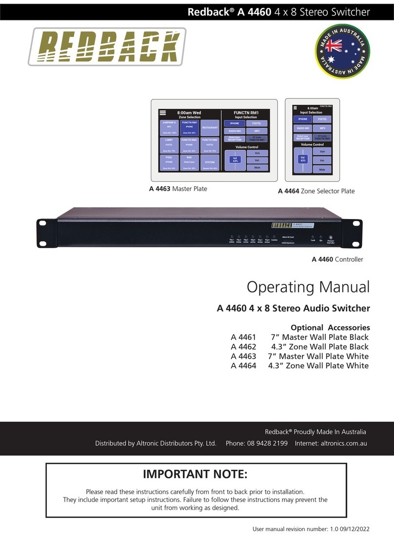
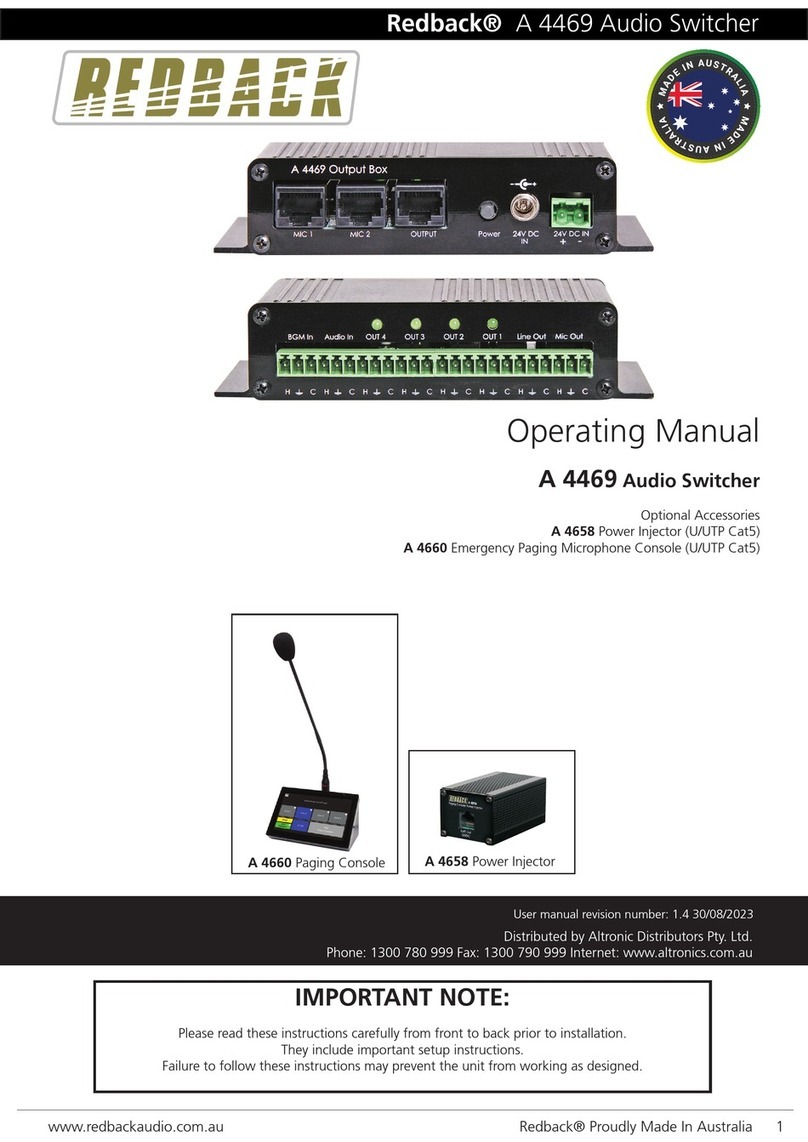
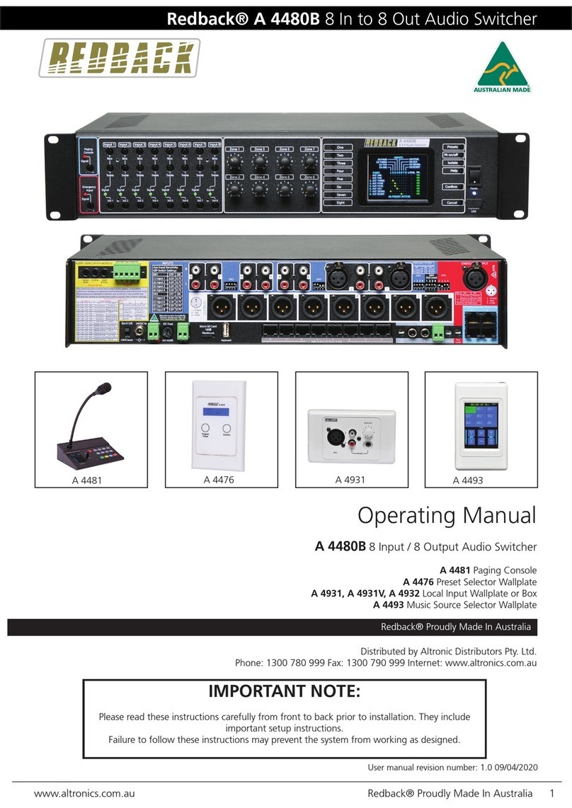
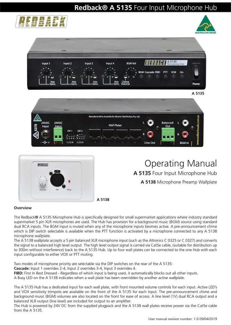
Redback A 4931 User manual

Redback® A 4930 Four Output Mic/Line Hub
Operating Manual
A 4930 Four Output Mic/Line Hub
A 4931 Mic/Line Preamp Wallplate
Overview
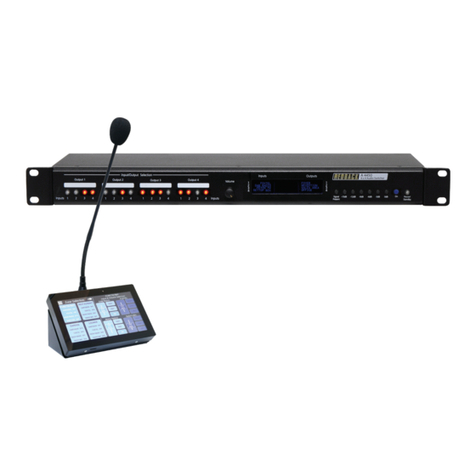
The Redback A 4930 Microphone/Line Hub is designed to accept audio from up to four A 4931 Mic/Line Preamp wallplates.
The A 4931 wallplate accepts either a microphone or line input and converts the signal to a balanced high level output. The
high level output signal is carried via Cat5e cable, (suitable for distribution up to 300m without interference) back to the
A 4930 Hub. Mic input is via a balanced XLR whilst the line input is via 2 x RCA sockets or 3.5mm audio jack for portable
devices with a lower level line output.
The A 4930 Hub has a dedicated output for each wall plate, with front mounted volume controls for each output. Each
output can be DIP switch selected to be fed to a dedicated mixed output. Each output including the mixed output has DIP
switch selectable balanced mic/line, or unbalanced line level outputs which can be fed directly into ampliers.
The Hub is powered by 24V DC from the supplied plugpack and the A 4931 wallplates receive power down the Cat5e cable.
User manual revision number: 1.0 11/09/2018
A 4931
A 4930

www.redbackaudio.com.auRedback® Proudly Made In Australia2
Redback® A 4930 Four Output Mic/Line Hub
CONNECTIONS
Figure 1 illustrates a typical wiring conguration for the A 4930 Hub.
In this example Output 1 and Output 2 are both fed into the line inputs of ampliers. Switches 1 and 4 of DIP1 are both set to OFF for Line Level output from the A 4930 (see DIP
switch settings for more details). Output 3 and output 4 are both fed into the Microphone inputs of ampliers. Switches 1 and 4 of DIP2 are both set to ON for Mic level output out
of the A 4930. The mixed output is being fed into a line level input of an amplier so switch 1 of DIP is set to OFF. Switches 2 and 3 of DIP1 are set to ON signifying that hte audio
from Outputs 1 and 2 will be piped to the mixed output.
1 2 3 41 2 3 41 2 3 4
Manufactured in Australia
24VDC
Input
+-
www.redbackaudio.com.au
Output 1
Mic -
Aux Out
24VDC
Input
+_
Wall Plates
3 4
12
Mic +
Gnd
1 2 3 4
SW 1
Output 2
Mic -
Aux Out
Mic +
Gnd
Mixed
Mic -
Aux Out
Mic +
Gnd
Output 4
Mic -
Aux Out
Mic +
Gnd
Output 3
Mic -
Aux Out
Mic +
Gnd
Output
By Altronic Distributors Pty. Ltd.
SW 1 DIP Switch Settings
SW ON OFF
1
2
Output 1 Mixed
3
4
Output 1 Mic Lvl Output 1 line Lvl
Output 2 Mixed
Output 2 Mic Lvl Output 2 line Lvl
SW 2 DIP Switch Settings
SW ON OFF
1
2
Output 3 Mixed
3
4
Output 3 Mic Lvl Output 3 line Lvl
Output 4 Mixed
Output 4 Mic Lvl Output 4 line Lvl
SW 3 DIP Switch Settings
SW ON OFF
1
2
Not Used
3
4
Not Used
Not Used
M/Output Mic Lvl M/Output line Lvl
1 2 3 4
SW 2
1 2 3 4
SW 3
Line Mic
L
R
OUTPUT +
–
2 1
3
OUTPUT 1 AMPLIFIER
Mono Output
Line Mic
L
R
OUTPUT +
–
2 1
3
OUTPUT 2 AMPLIFIER
Line Mic
L
R
OUTPUT +
–
2 1
3
OUTPUT 3 AMPLIFIER
Line Mic
L
R
OUTPUT +
–
2 1
3
OUTPUT 4 AMPLIFIER
1 2 3 4
ON
Rear of A 4931 WallPlate
1 2 3 4
ON
(Maximum 300m)
(Maximum 300m)
(Maximum 300m)
(Maximum 300m)
Mono Output
Line Mic
L
R
OUTPUT +
–
2 1
3
MIXED OUTPUT AMPLIFIER
Mono Output
Balanced Output
Balanced Output
1 2 3 4
ON
1 2 3 4
ON
Rear of A 4931 WallPlate

Redback® A 4930 Four Output Mic/Line Hub
www.redbackaudio.com.au Redback® Proudly Made In Australia 3
Redback® A 4930 Four Output Mic/Line Hub
A 4930 DIP Switch Settings
The audio from the outputs of the A 4930 are available as a Aux output and/or a balanced output which can be set to be
either microphone level or line level. As well as having dedicated outputs, each of these outputs can also be directed to the
mixed output. These options are set by the DIP switches on the rear of the A 4930.
The DIP switch features are outlined below.
DIP 1
Switch 1 - Sets Balanced Output 2 to Mic or Line level output. ON - Mic Level Output, OFF - Line Level Output.
Switch 2 - When set to ON, Output 2 is fed to the mixed output.
Switch 3 - When set to ON, Output 1 is fed to the mixed output.
Switch 4 - Sets Balanced Output 1 to Mic or Line level output. ON - Mic Level Output, OFF - Line Level Output.
DIP 2
Switch 1 - Sets Balanced Output 4 to Mic or Line level output. ON - Mic Level Output, OFF - Line Level Output.
Switch 2 - When set to ON, Output 4 is fed to the mixed output.
Switch 3 - When set to ON, Output 3 is fed to the mixed output.
Switch 4 - Sets Balanced Output 3 to Mic or Line level output. ON - Mic Level Output, OFF - Line Level Output.
DIP 3
Switch 1 - Sets the Balanced Mixed Output to Mic or Line level output. ON - Mic Level Output, OFF - Line Level Output.
Switch 2 - Not Used.
Switch 3 - Not Used.
Switch 4 - Not Used.
A 4931 Audio Output, VOX Settings and VOX sensitivity
The A 4931 has a set of DIP switches on the rear which determine how the audio is output from the wallplate.
The DIP switches are labelled 1) VOX BOTH, 2) VOX ENABLE, 3) VOX OUTPUT.
When the A 4931 is used with the A 4930 there are only two possible audio output options.
1) The audio from the A 4931 wallplate microphone input and the line and/or music inputs are mixed together and output
to the A 4930 Hub.
DIP Switches set as follows: 1-OFF ,2-OFF, 3-OFF
2) The A 4931 wallplate microphone input has VOX priority over the line and music inputs. I.e. the audio from the line/Music
inputs will be over ridden by the MIc input when a microphone is used.
DIP Switches set as follows: 1-OFF ,2-ON, 3-OFF.
The VOX sensitivity of the microphone is adjusted by the trimpot on the rear of the A 4931 labelled “VOX”.
DIP SWITCHES
VOX SENSITIVITY
A 4931

www.redbackaudio.com.auRedback® Proudly Made In Australia4
Redback® A 4930 Four Output Mic/Line Hub
A 4930 Specications
OUTPUT MIC LEVEL:....................................................3mV
OUTPUT LINE LEVEL:.......................................................1V
OUTPUT CONNECTORS:
Audio Outputs: ........................Euroblock terminals
INPUT CONNECTORS:
Wall Plate Inputs:................................. RJ45 8P8C
24V DC Power :..............2.1mm JACK (centre +ve)
24V DC Power :....................... Euroblock terminals
CONTROLS:
Volume1-4: ...................................... Front Volume
POWER SUPPLY: ...................................... 24V DC @ 1 Amp
DIMENSIONS:≈.................................... 210W x 122D x 44H
WEIGHT: ≈................................................................ 0.4 kg
A 4931 Specications
INPUT MIC LEVEL SENSITIVITY:......................................3mV
INPUT LINE LEVEL SENSITIVITY:.........................................1V
MUSIC INPUT LEVEL SENSITIVITY: .............................200mV
OUTPUT CONNECTOR: ...................................... RJ45 8P8C
INPUT CONNECTORS:
AUDIO : ......................3 pin XLR balanced
....................................... 2 x RCA
............................... 3.5mm JACK
24V DC Power :..............2.1mm JACK (centre +ve)
...................... Euroblock terminals
All Australian made Redback products are covered by a 10 year warranty.
Should a product become faulty please contact us to obtain a return authorisation number. Please ensure you have all the
relevant documentation on hand. We do not accept unauthorised returns. Proof of purchase is required so please retain
your invoice.
Distributed by Altronic Distributors Pty. Ltd. Perth. Western Australia.
Phone: 1300 780 999 Fax: 1300 790 999 Internet: www.altronics.com.au
RJ45 cabling conguration for system components (586A ‘Straight through’)
System components are connected using “pin to pin” conguration RJ45 data cabling as shown below. When installing
ensure all connections are veried with a LAN cable tester before switching any system component on.
Failure to follow the correct wiring conguration may result in damage to system components.
Troubleshooting
NO Power (Power LED does not illuminate):
Check power supply DC jack is 2.1mm and not 2.5mm size.
Check polarity of 24V DC supply.
Wall not operating correctly:
Check RJ45 cabling is correct.
586A
1 TX+
2 TX-
3 RX +
4
5
6 RX-
7
8
StraightThrough
(both ends)
Pins Face Upwards
1 TX+
2 TX-
3 RX +
4
5
6 RX-
7
8
Other manuals for A 4931
2
This manual suits for next models
1
Table of contents
Other Redback Switch manuals
Popular Switch manuals by other brands

MikroTik
MikroTik CCR1009-7G-1C-PC quick start guide

steute
steute RF 95 EN868 Series Mounting and wiring instructions

Veris Industries
Veris Industries Hawkeye 909 installation guide

TP-Link
TP-Link TL-SG1210MP installation guide

Fema
Fema DCM Series Assembly and operating instructions

VICOR
VICOR FlatPAC-EN user guide