Apco 2LIGHT TANDEM PILOT HARNESS User manual

www.apcoaviation.com
7 Chalamish St., Ind. Park Caesarea, 3088900 ISRAEL
2022 11 17 (rev. 1.02)

www.apcoaviation.com
2
CONTENTS:
1 DISCLAIMER OF LIABILITY 3
2 INTRODUCTION 3
3 TECHNICAL DATA 3
4 CONSTRUCTION 3
5 PROTECTION 3
6 PARTS & ASSEMBLY 4
7 USE 20
8 INSPECTION AND MAINTENANCE 21
WARNING
This is not a training manual. It is extremely dangerous to yourself and others to use this product without first completing a flying course given by a qualified
instructor.
Apco Aviation's products are carefully manufactured and inspected by the factory. Please use the product only as described in this manual. Do not make any
changes to the product.
AS WITH ANY SPORT - WITHOUT TAKING THE APPROPRIATE PRECAUTIONS, PARAGLIDING CAN BE DANGEROUS.

www.apcoaviation.com
3
1 DISCLAIMER OF LIABILITY
Taking into consideration the inherent risk in paragliding or hang gliding, (free flying and motorized), it must be expressly understood that the manufacturer and
seller do not assume any responsibility for accidents, losses and direct or indirect damage following the use or misuse of this product.
APCO Aviation Ltd. is engaged in the manufacture and sale of hang gliding, paragliding, motorized Para/hang gliding and emergency parachute equipment.
This equipment should be used under proper conditions and after proper instruction from a qualified instructor. APCO Aviation Ltd. has no control over the use of
this equipment and a person using this equipment assumes all risks of damage or injury.
APCO Aviation Ltd. disclaims any liability or responsibility for injuries or damages resulting from the use of this equipment.
The equipment is designed to perform in the frame of the required certification.
2 INTRODUCTION
The 2 Light Harness is an all new, ground up designed split-leg harness, aimed at the tandem pilot, but is equally doubles as a solo harness, featuring options like
reserve bridle shoulder attachment points* , and speed system pulley attachment points. It has integral airfoam back protection, with a lexan sheet for load
distribution. The harness can be upgraded with additional, in flight accessible, side pockets, which may come in handy for a camera, snacks or to stow extra gear
on multi day trips.
*for solo use only!
3 TECHNICAL DATA
4 CONSTRUCTION
In line with APCO’s tradition, the 2 Light does not compromise whatsoever on durability, safety or comfort.
We carefully chose materials, and where they are used on the harness using past experience to guide us, in the quest to make a lightweight yet durable harness.
5 PROTECTION
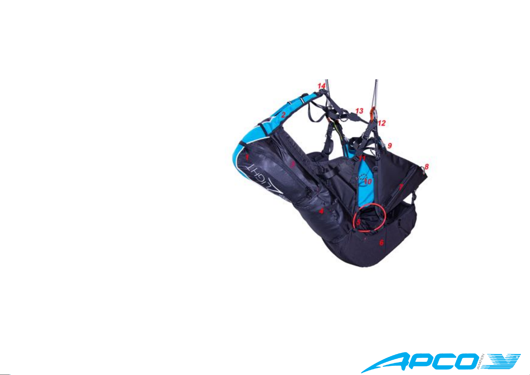
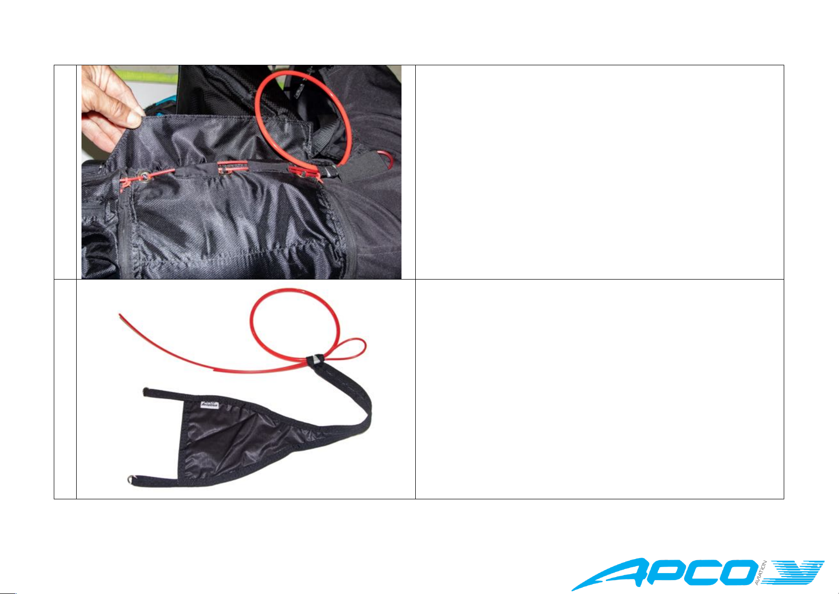
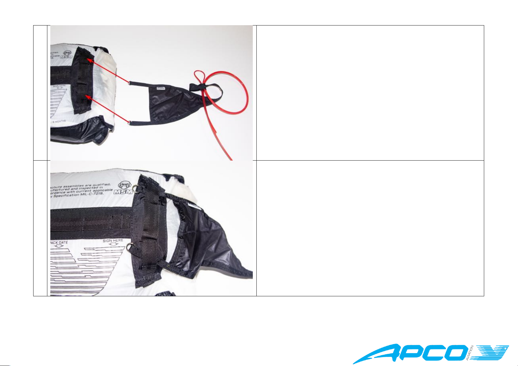
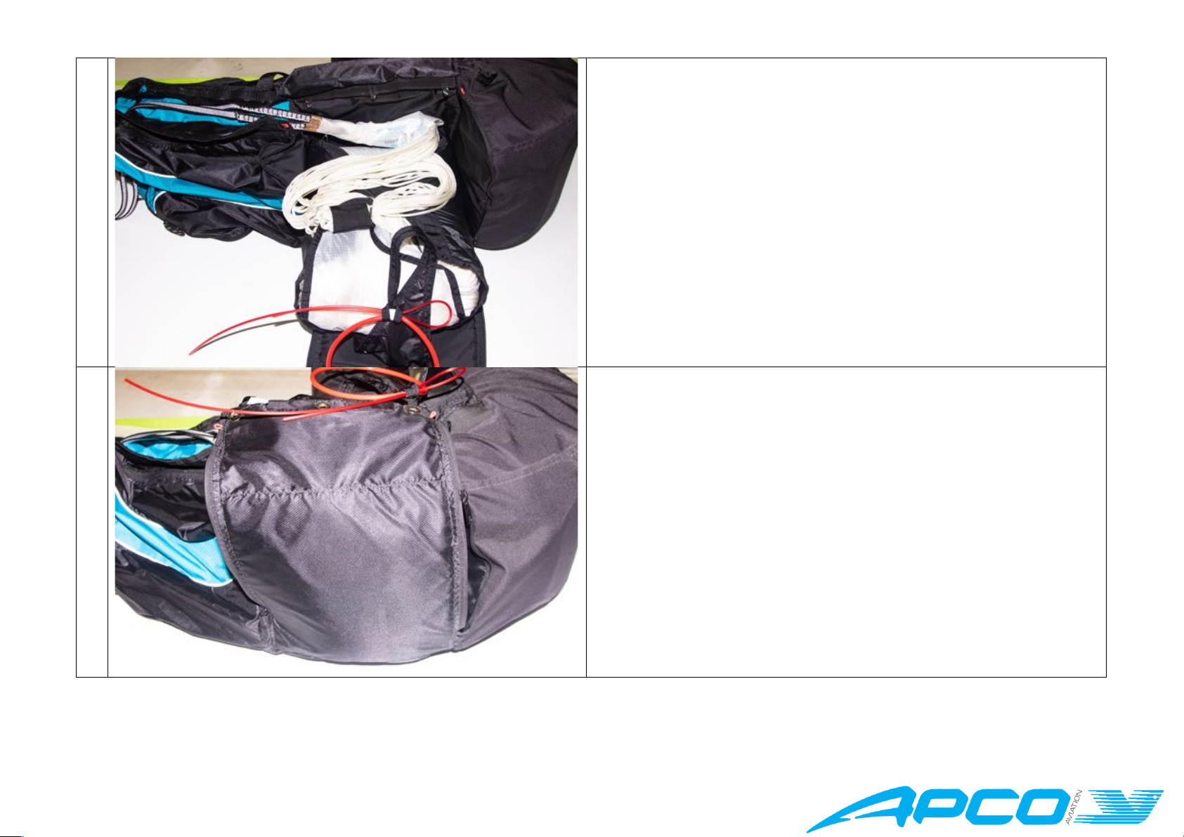
The 2 Light has an integral emergency parachute container with zipped closure system for both the container and bridle. It is suitable for both tandem and solo
flying. The shoulder attachment points are for solo flight only, and a tandem reserve should be connected to the main point of the spreader bars. The harness has
an integral airfoam back protector, which forms part of the harness
2-LIGHT PILOT HARNESS
SPECIFICATIONS
Code
42610
Pilot Size
155 – 185cm
Max Load
120kg
Weight
2450gr
Reserve container capacity
3000 - 7000 cc

www.apcoaviation.com
4
Reserve Container
The Reserve container is on the back, and the capacity is large enough to contain a large, standard weight tandem reserve parachute.
Airfoam Protector
The pilot protection system of the 2 Light forms an integral part of the pilot support, and should not be flown without it installed.
6 PARTS & ASSEMBLY
The following parts make up the 2Light Pilot Harness
1. Rear Storage Compartment
2. Solo Reserve Attachment Loops (covered)
3. Reserve Bridle cover
4. Reserve Compartment
5. Reserve Handle
6. Airfoam Protector
7. Accessory Pocket Zip
8. Speed System Guide Ring
9. “Get-Up” Closure buckle
10. Speed system pulley (optional) attachment
Loop
11. Lumbar Support Adjuster
12. Hang Point
13. Reserve bridle routing point
14. Shoulder Strap Adjuster
6.1 Adjustment
It is best practice to hang and adjust the harness in a simulator, with the reserve installed, and the back compartment packed as it would be in flight. In the case of
Tandem, do this with the spreader bars and passenger with the intended passenger harness included in the system.
6.2 Reserve Installation
The reserve should be installed by a professional or other competent person, using these instructions as basic guideline. a Test deployment should be done in a
simulator, to ensure that the installation is correct, and then re-installed.

www.apcoaviation.com
5
Installation Instructions (Tandem configuration):
1
Open the magnetic flap covering the reserve closure system and carefully
examine the way it has been closed at the factory, so that you will be able to
repeat the closure in the same way.
2
Open the reserve container by pulling the handle out.
The Handle is supplied with a spreader to attach to the reserve deployment bag,
and it is designed to be compatible with Apco deployment bags that have two
correctly spaced attachment points. The spread of the two points makes it
easier to extract the reserve from the harness, and reduces the chances of
snagging in the glider lines.

www.apcoaviation.com
6
3
Attach the handle to the deployment bag here
4
Use girth hitches that are closed with the supplied split-rings.

www.apcoaviation.com
7
5
6

www.apcoaviation.com
8
7
8
Repeat the above steps to attach the second loop in the same way.

www.apcoaviation.com
9
9
Lay the harness on its left side.
Pull down the reserve container flap so that the zippers are open while the
zip toggles are stowed in the bays.
Place the reserve on top of the closure flap, with the opening of the
deployment bag facing upwards, and the handle towards you as shown.
Neatly lay the lines and excess riser into the bottom of the container.
10
Using the reserve container closure flap, lift the reserve into the harness
container, and close the zips by running the zippers up to the locking loops
and back down to their bays, ensuring not to trap any part of the reserve or
deployment bag in the zips. Stow the zip toggles in their bays.

www.apcoaviation.com
10
11
Fit the deployment handle into its retainer as shown
12
Next, lock the zip closure loop with the short locking “pin”
The loop attached to the closing flap should go through the loop on the
base of the harness.

www.apcoaviation.com
11
13
Lock the first of the three main closures also using the short locking “pin”,
and then pass it under the sleeve.
This lock should be done under the deployment handle leash (See pic /
step 14 and 15)
NB. DO NOT LOCK THIS LOOP WITH THE LONG PIN.
14
Run both locking pins through the 1st guide sleeve.
Note the deployment handle leash running over the first of the main locking
loops, and entering the container before the second lock.

www.apcoaviation.com
12
15
Lock the 2nd main locking loop also using ONLY the short locking pin.
Note the pin will pass a bit further through the loop than what is shown
here, and the end of the pin should be inserted into the 2nd guide sleeve.
16
Lock the 3rd main closing loop with the long locking pin

www.apcoaviation.com
13
17
Close the Velcro over the bridle sleeve, and at this point you may need to
re-close the zipper, again, ensuring not to trap anything in the zip
18
and stow the toggle in its bay.

www.apcoaviation.com
14
19
Now close the zip locking loop by passing the loop on the closing flap of
the container through the loop on the bridle sleeve on the harness, stowing
the end of the pin inside the slot in the sleeve.
20
Do a final check before closing the magnetic flap over the closure system

www.apcoaviation.com
15
21
Close the flap
22
Use the two Velcro retainers to fix the handle in place.
Hang the harness in a simulator, and do a test deployment while sitting in
the harness, to ensure the installation is correct and working smoothly,
and the re-install it as it was before.

www.apcoaviation.com
16
23
Close the Velcro flap from the container up the side of the harness over the
bridles, ensuring there are no twists.
Separate the two bridles at the shoulders
24
Routing one to exit on each shoulder

www.apcoaviation.com
17
25
The bridle should have a UV protection sleeve that is long enough to
protect the bridle from the spreader bars up to the point where it enters
the cover on the shoulder straps.
26
Route the bridles down the shoulder webbings

www.apcoaviation.com
18
27
Use the Velcro keepers to keep the bridles tidy
28
Consult the instructions supplied with your spreader bars…
Attach the two bridles to the spreader bars according to the instructions of
your spreader bars.
INSTALLATION SUMMARY
Ensure that the reserve has two suitably long bridles, that will reach the main point on top of the spreader bars.
Attach the deployment handle to the deployment bag with Girth-hitch knots, on the two points of the container.
Insert the reserve into the reserve compartment, with the handle attachment point to the outside right side of the harness.
Close the compartment zips, taking care not to catch anything in the zips, and stow the zipper toggles in their covers.
Lock the reserve in place with the locking loops using pull-up cords through the loops, and insert the locking “pins” into the loops.
Route the double bridles up to the shoulders and close the cover, then separate the bridles to left and right, and put them into the shoulder pad covers.
Route the bridles down the shoulder straps, and put them into the provided guides, then up to the main points on top of the spreader bars, and attach according to
the instructions of the spreader bar.Check the length of the bridles by hanging in a simulator.
Installation Instructions (Solo configuration):
Follow the above instructions, but attach the bridles of the solo reserve to the shoulder attachment loops.
NB. NEVER fly tandem with a solo reserve, nor with any reserve that is attached to the shoulders of the pilot!
Deployment Instructions:
The reserve is deployed by hand and should be done in the following sequence:
Look, Grab, Pull, Throw. The reserve handle is attached to the reserve deployment bag, and the handle must be released when throwing the reserve.
It is recommended to disable the glider, ideally, if there is enough time, by pulling it in so that you are holding the entire canopy in your arms. If there is not enough

www.apcoaviation.com
19
time, try to stall the wing by wrapping the brakes and pulling as much as possible, or by locating the B-Risers and pulling them down. This will stabilize the decent
by preventing the reserve and the main from opposing each other – aka down planing, which increases the sink rate significantly.
Repack Interval:
The reserve parachute should be repacked according to the reserve manufacturers recommendations, all other parts, such as the reserve bridles should be
inspected regularly, and replaced if looking worn, or older than five years.
6.3 Side Pocket
The 2-Light harness is compatible with the zipped-on Side Pocket (Code: 80038).
It can be installed on the left, right or on both sides. It is installed by attaching the zip of the pocket to the zip on the side of the harness, and then clipping the
webbing loop around the side leg support strap of the harness.
6.4 Ball Bearing Pulley
The 2Light Pilot Harness is compatible with the Ball Bearing Pulley (Code: 43107B).
The Pullies are supplied in pairs, one for each side. Install the pulley as shown in the image below, by hitching it onto the loop on the harness.
6.5 Speed System (Solo Flight)
The 2-Light harness is compatible with the WonderBar (Code: 43107C) speed system line and stirrup or other similar speed bars. You will need the optional Ball
Bearing Pulleys installed on the sides of the harness on the provided loops using Girth-hitch knots as shown.
To install the WonderBar, remove the Brummel hooks and chord locks from the ends of the lines.
Ensure that you install the bar the correct way up. Route the speed system lines through the retainer rings, then through the black aluminum pullies, then through
the ball bearing pullies. Put the chord locks back on the lines, followed by the Brummel hooks. The Chord locks are used to keep the speed system away from the

www.apcoaviation.com
20
ground and your legs for the takeoff. You can also raise it again before landing if time / conditions allow. Do a hang check and adjust the length of the Speed
system to that enough free travel before engaging the speed system so that the speed system is not engaged when in a standing position or while seated during
normal flight. Refer to the instructions of your wing for advice on how best to use the speed bar. Do not use the speed system in turbulence or at low altitudes
above ground.
7 USE
7.1 Closing the harness
During your pre-flight, before putting on the harness, besides all the other points on your checklist, always check that the reserve container is closed correctly, and
that the speed system is not interfering with the reserve system.
Lift the harness onto your back using the shoulder straps.
Close the two “Get-Up” legs straps, followed by the shoulder retaining strap across the chest.
Check that the speed system (if installed) is kept high with the chord locks.
7.2 Attaching the Glider / Risers
Always first set up and adjust your setup using a simulator using a simulator before the first flight Once correctly set up, attaching the risers to the flight carabiners
is straightforward. Always ensure that the carabiners are installed correctly onto the harness and spreader bars, and that they are closed and locked once the risers
are attached.
7.3 Pre-flight
Do a thorough Pre-flight check;
• Harness is in airworthy condition, and attached correctly to the spreaders and reserve.
• Reserve container closed and handle in place
• All buckles and closures locked in correct sequence
• Wing attached to spreaders correctly
• Passenger harness closed correctly, and attached to spreaders correctly
• Speed System attached, and not interfering with reserve container / handle (if present)
• Wing setup according to glider manual
7.4 Take off, sitting, flight and Landing
After takeoff, first ensure your flightpath is clear and safe with sufficient height before sitting into the harness. To sit into the harness, lift and bend your knees and
slide into the seat. During flight it is also possible to steer using weight shift.
CAUTION:
ADJUSTING THE SPEED BAR TOO SHORT MAY CAUSE IT TO BE APPLIED CONTINIOUSLY DURING FLIGHT – MAKE SURE
TO TEST THE ADJUSTMENT BY HANGING THE HARNESS WITH RISERS ATTACHED TO THE CHECK THE ADJUSTMENT IS
CORRECT AND SAFE.
Table of contents
Other Apco Aircraft manuals