Apco F1 User manual

www.apcoaviation.com
7 Chalamish St., Ind. Park Caesarea, 3088900 ISRAEL
2020/01/01 (rev. 1.07) offline

www.apcoaviation.com
2
CONTENTS:
1DISCLAIMER OF LIABILITY 4
2INTRODUCTION 4
3TECHNICAL DATA 5
4CONSTRUCTION 6
5MATERIALS 6
6FLEXON® Batten system: 7
7TRIMMING 7
8HARNESS 7
9EMERGENCY PARACHUTE 8
10 SPEED SYSTEM 8
11 RISERS 9
12 TRIMMERS 11
13 OAA (One Action Acceleration) 12
14 HIT VALVES (High-speed In-Take) 13
15 GENERAL INSPECTION 13
16 PARAGLIDING 18
17 POWERED FLYING 25
18 PACKING 32
19 MAINTENANCE & CLEANING 32
20 BUTT HOLE II (Auto Debris release valves) 33
21 STORAGE 33
22 DAMAGE 33
23 THREE YEAR WARRANTY 34
24 GENERAL ADVICE 35
25 F1 - 18 - SKETCHES 36
26 F1 –20 - SKETCHES 38
27 F1 - 22 - SKETCHES 39

www.apcoaviation.com
3
WARNING
This is not a training manual. It is extremely dangerous to yourself and others to attempt to fly this or any paraglider without first completing a flying course given by a
qualified instructor.
Apco Aviation's gliders are carefully manufactured and inspected by the factory. Please use the glider only as described in this manual. Do not make any changes to the
glider.
AS WITH ANY SPORT - WITHOUT TAKING THE APPROPRIATE PRECAUTIONS, PARAGLIDING CAN BE DANGEROUS.

www.apcoaviation.com
4
1DISCLAIMER OF LIABILITY
Taking into consideration the inherent risk in paragliding or hang gliding, (free flying and motorized), it must be expressly understood that the manufacturer and seller do not
assume any responsibility for accidents, losses and direct or indirect damage following the use or misuse of this product.
APCO Aviation Ltd. is engaged in the manufacture and sale of hang gliding, paragliding, motorized Para/hang gliding and emergency parachute equipment.
This equipment should be used under proper conditions and after proper instruction from a qualified instructor. APCO Aviation Ltd. has no control over the use of this
equipment and a person using this equipment assumes all risks of damage or injury.
APCO Aviation Ltd. disclaims any liability or responsibility for injuries or damages resulting from the use of this equipment.
The glider is designed to perform in the frame of the required class as certified.
2INTRODUCTION
The F1 is the result of our quest to bring safe, top speed and performance at incredible efficiency to
experienced pilots across all paramotor disciplines.
The F1 uses an advanced Reflex profile, to increase both performance and stability throughout the
speed range.
The sail tension has been optimised to give the wing incredible rigidity without negatively affecting
performance, so the wing is and feels very solid and reassuring in flight.
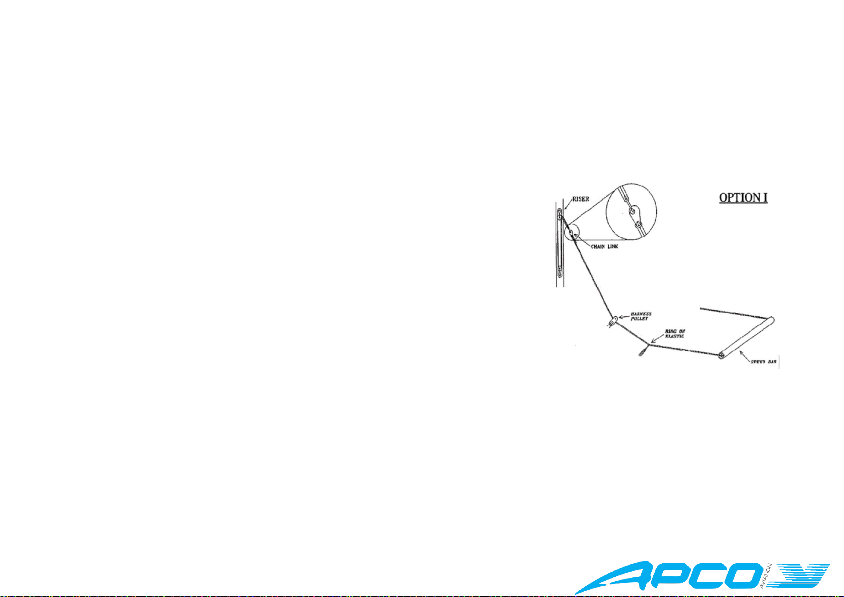
The riser / speed system / trim system was re-designed to incorporate all of Apco’s ground-breaking
technologies, and has a greater usable range than any wing we have built before, meaning you can
launch and land at reasonable speeds, but open up with comfort for the race, or the perfect long
distance XC flight you’ve been dreaming about –but, be warned, unless your friends are on the F1 too,
you will be flying alone.
Although the F1 is not a dual-use wing, with the trimmers closed, the F1 will thermal much like a
paraglider, and has exceptional glide ratio too, so if you like to mix it up on a good day, idle or cut the
motor and crank it up to cloudbase with ease.
Handling is precise and predictable, with the ability to turn anything from a flat low sink rate
thermaling turn, to slalom perfection.
Inflation is very easy, and does not tend to overfly the pilot.

www.apcoaviation.com
5
TECHNICAL DATA
F1 / Size
18
20
22
Code
22818
22820
22822
Cells
64
64
64
Area [m2]
18
20
22.0
Area (projected) [m2]
15.26
16.95
18.65
Span (incl. Stabilizer) [m]
10.90
11.49
12.05
Span (projected) [m]
8.64
9.10
9.55
Aspect Ratio
6.6
6.6
6.6
Aspect Ratio (projected)
4.6
4.6
4.6
Weight Range (all up) Paramotor [kg]
70-100
70-120
70-140
Weight Range (all up) Para-Trike [kg]
70-120
70-140
70-165
Canopy Weight [kg]
3.9*
4.2*
4.6
Root Cord m
1.92
2.02
2.21
Tip Chord [m]
0.12
0.13
0.14
Length of Lines on B [m]
6.59
6.95
7.29
Total Length of Lines [m]
334
352
370

www.apcoaviation.com
6
V-min [km/h] at optimal wing loading*
27
V-trim (closed) [km/h]
38 - 42
V-trim (neutral) [km/h]
45 - 49
V-trim (open) [km/h]
55 - 59
V-max [km/h]
80
Min Sink [m/s] at optimal wing loading
1.2 m/sec
*All Data measured at sea level, using a combination of GPS and Speed Probe, averaged over several runs
3CONSTRUCTION
The glider is constructed with a top and bottom surface, connected by ribs. One top and bottom panel, together with the connecting ribs is called a cell. Each cell has an
opening on the front lower part. The cells fill with air forcing the panels to take the shape dictated by the air-foil (rib) section.
On either side the wing ends in a stabilizer or wing tip, which provides straight-line (Yaw) stability and produces some outward lift to keep the span-wise tension.
The front part of the ribs use APCO's FLEXON batten system to keep the leading edge shaped at high speeds and in turbulent air. They also improve the performance and the
launch characteristics of the glider.
The line hook-up points are made of Dyneema and imbedded in the bottom surface of the wing for minimal drag and maximum performance.
4MATERIALS
The glider is made from tear resistant Ripstop Nylon cloth, which is P.U. coated to zero porosity and then siliconized to give the fabric high resistance to the elements.
Different cloth is used for the top, bottom and ribs due to their different functions.
The lines are made of superaramide covered with a polyester sheath for protection against UV, wear and abrasion.
The bottom section of the brake lines is made of polyester because of its better mechanical properties.
The maillon quick links that attach the lines to the risers are made of stainless steel.

www.apcoaviation.com
7
5FLEXON® Batten system:
New generation FLEXON ® batten system incorporated (see below) in the leading
edge of the ribs, insuring perfect profile shape (instead of traditional Mylar
reinforcement). FLEXON ® battens reduce the weight of the glider by an additional
500gr. and unlike Mylar reinforcement will guarantee no deterioration in
performance or launch.
Additional advantage of FLEXON batten is that it is practically indestructible,
safeguarding the performance and launch over the lifespan of the glider.
6TRIMMING
All Apco gliders are trimmed for optimum performance combined with unsurpassed safety. It is very important not to re-trim or tamper with any
of the lines or risers as this may alter the performance and safety. Trimming of the brake line should be done in accordance with this manual and
carefully checked before flying.
7HARNESS
All of Apco's gliders are developed with the use of ABS (Automatic Bracing System) type harnesses without cross bracing. We recommend the use
of an ABS harness with all our gliders. All certified harnesses can be used with our gliders. For best safety and performance, we recommend an
Apco harness equipped with a Mayday emergency parachute.
CAUTION:
WE RECOMMEND NOT TO USE CROSS BRACING STRAPS.
APCO GLIDERS ARE DEVELOPED AND TESTED WITHOUT THE USE OF CROSS BRACING. USING AN ABS
HARNESS WITH CHEST STRAP SET AT THE SPECIFIED WIDTH (CHECK THE CERTIFICATION STICKER ON
YOUR GLIDER) WILL RESULT IN THE HIGHEST PASSIVE SAFETY ON YOUR GLIDER.

www.apcoaviation.com
8
8EMERGENCY PARACHUTE
It is recommended to use a certified rescue parachute when flying, no matter your intended altitude or flying style.
Attaching the rescue parachute should be done in accordance with the recommendations of the harness and reserve parachute manufacturer.
When we fly the F1, we use the SLT Low, or Split-Leg Low, combined with the Light and compact Mayday SQ Parachute, packed in the
matching side mounted reserve container. Always check the reserve handle and locking pins during every pre-flight check.
9SPEED SYSTEM
ASSEMBLY & ADJUSTMENT
Apco gliders can be ordered with the Wonder-Bar, which
First attach the harness to the glider. Remove the Chain Link from the end of the accelerator
line attached to the speed bar, then thread it through the elasticized ring on the harness, then
through harness pulley and then re-attach it to the Chain link with a larks-head knot. Hook the
Chain link onto the Chain Link on the riser of the corresponding side. Sit in the harness and
have someone hold the riser up in a flying position for you. Adjust the speed bar line by pulling
the end through the speed bar tube and moving the knot. The Bar should be about 10 cm (or
closer if you have a second step) away from the front of the harness seat. This allows you to
easily reach the bar with your foot, and will allow you to use the full range of the speed bar if
you extend your legs fully. Do not adjust the speed system too short, as this will cause it to be
activated permanently while flying, and could be dangerous. It is possible to fit a second step to
the system, if one has trouble using the full range of the system (supplied separately).
WARNING:
The use of the speed system in turbulent conditions or close to the ground is dangerous. While flying with the accelerator,
the glider has a reduced angle of attack and is therefore more susceptible to turbulence and may collapse or partially
deflate. Gliders react faster when accelerated and may turn more. The accelerator should immediately be released in this
case.

www.apcoaviation.com
9
10 RISERS
The F1 is supplied with risers featuring a split A riser. The 1st A-riser attaches
to the central two A lines (A1 & A3). The second A-riser is attached to the
outermost A line (A5). At no time should the pilot change the risers or use
risers not intended for this specific glider as this will affect the performance
and safety of the glider.
The riser is equipped with both an accelerator and trimmers.
The brake line is guided through upper pulley for low hook in point harnesses
and adjusted as per Section 16.2(see Figure 16-1).
For high hook in harnesses use the same brake line setting guiding the brake
line through

www.apcoaviation.com
10

www.apcoaviation.com
11
11 TRIMMERS
The F1 risers are equipped with trimmers which
are replaceable.
The neutral setting is when the A/B/C/D risers
legs are of equal length in flight (blue mark on the
trim webbing.
For Take-off and landing, the trimmers should be in the closed
(minimum trim speed) position. After take-off set them to the
neutral position, and close them again before landing. They can also
be set asymmetrically to compensate for torque effect. The Trim
System of the F1 is very effective for accelerating the wing on long
flights, when staying on bar may not be comfortable. The trim
system differs from previous Apco gliders in that it releases the B
riser, which gives a clean rotation of the profile, and is very
efficient.

www.apcoaviation.com
12
12 OAA (One Action Acceleration)
OAA is an innovative system that stands for "One action acceleration system - OAA".
OAA allows pilots to simultaneously operate both the speed system and the trimmer for optimized angle of attack at any
given speed. With OAA unlocked, the speed bar simulates, the release of the trimmers according to the position of the speed
bar. This allows for a larger speed range that can be fully used in one smooth action of the speed bar to reach the maximum speed of the wing
without the need to release the trimmers.
In order to use the OAA one must unlock the Brummel hooks connected to the rear of the risers below the trimmers. Prior to using the speed
system, one must move the trimmers to the neutral position, at the blue mark on the trim webbing (all risers will be level in flight).
To Lock the OAA one must lock the Brummel
hooks together on the rear riser.
If using the Speed Bar with the OAA Locked, and
you wish to be able to reach the maximum speed,
you must release the trimmers to the fully open
position before applying the Speed Bar. The
required force to apply the Speed Bar will be
higher.
In turbulent conditions, we recommend not flying
at max speed with the trimmers fully released.
With the OAA Unlocked, we recommend not
releasing the trimmers fully and then applying full
speed bar. This will not give a greater speed range,
and will make recovery from collapses slower.

www.apcoaviation.com
13
13 HIT VALVES (High-speed In-Take)
The F1 is equipped with an Active HIT Valve system (patent pending) to
improve the overall performance and safety of the wing especially during
accelerated flight.
The valve system allows maximum inflow of air when the glider acquires a lower angle of
attack while accelerated. HIT valves open and close in flight to increase the internal pressure of
the glider.
For the valves to work properly it is important to keep them wrinkle free especially in sub zero
temperatures. Make sure the valves are lying flat and are in the closed position when you fold
the glider. Before launch the pilot should check all the valves and verify that they are flat and
cover the entire area of the mesh opening. Creased and wrinkled valves will not adversely affect the safety of the wing.
14 GENERAL INSPECTION
Pilots, please ensure that your glider has been test flown and fully checked by your dealer before taking it into your possession.
Verify that the dealer checked and confirms that the glider is airworthy.
In case of use of the wing in combination with trike:
Due to the very wide assortment of trikes on the market with different set up and design, it is necessary to verify that the specific trike can be
successfully coupled with the wing.
Please make sure your dealer performs the following procedures before first flight:
A. It was checked with APCO that the specific trike can be flown with your new wing.
In case the specific combination is not checked by APCO –your dealer must take the following necessary steps :
B. Wing to be fully inspected by the dealer as in the paragraph above
C. Wing to be ground handled and visually checked while inflated.
D. Connection method to the trike is in line with APCO's recommendation according
to the sketch below. Pilot can reach both main brake handles and tip
steering handles (if available).

www.apcoaviation.com
14
E. Before first take-off perform "taxiing" test on the ground slowly rolling with the
wing checking all aspects of the set-up without actually taking off. (including
roll/yaw stability, pitch stability, stall tendency, brake response etc.)
F. Only once the wing passes the taxiing test –then the next step is to make the
actual test flight to make sure trike and wing are correctly coupled and the
system is airworthy.
G. Take the wing into your possession only after your dealer confirms that wing is
airworthy when coupled with your trike.
15 ANNUAL / PERIODICAL AIRWORTHINESS INSPECTION
It is highly recommended that your glider (and other equipment), undergo a Periodical Airworthiness Inspection which is to be done by Apco, or
an Apco approved / appointed service centre.
This is recommended to be done every 24 months or every 100 hours, whichever comes first.
This recommendation is in line with Israeli regulations, binding in Israel. as an alternative, we suggest for you to follow the regulations set by
your national authorities.
POROSITY:
Porosity is measured with a calibrated Porosimeter. It should be measured in at least 5 different places on the upper surface. Below is an example
of the sections we test at Apco. The upper surface, at 20-35% chord (from L/E) is most prone to becoming porous, and is thus the most important
section to test. It is also important to test the different cloth types, and different colours used.

www.apcoaviation.com
15
LINE MAINTENANCE
Superaramide lines are known to be sensitive to the influence of the elements. They must be carefully inspected periodically. In his/her own
interest, the pilot must observe the following points to ensure maximum performance and safety from the glider. Avoid sharp bending and
squeezing of lines. Take care that people do not step on the lines. Do not pull on the lines if they are caught on rocks or vegetation. Avoid getting
the lines wet. If they do get wet, dry them as soon as possible at room temperature and never store them wet.
One line of each line group (a, b, c, upper and lower) must be tested for minimum 50% of the rated strength. if the line fails under the load test or
does not return to its specified length all the corresponding lines must be replaced. never replace lines with different diameter or type of lines as
all gliders were flight and load tested for safety in their original configuration. Changing line diameter/strengths can have dangerous / fatal
consequences.
Professional use of gliders: towing, tandem, schooling and competition flying requires more frequent line inspection and replacement of A, B, C,
D and brake lines. For replacement lines please refer to our online direct line services.

www.apcoaviation.com
16
16 BEFORE THE FIRST FLIGHT
BRAKE SETTING
Before the first flight the pilot / dealer has to inflate the glider in the flight
configuration, on the intended frame, to check and if needed, adjust the brake
line length as required. It is important that the brakes are not set too short. If the
glider is above your head the brakes should have about 10 cm of free travel in
the brake from the brake guide on the riser to the activation point of the brakes
(See Diagram). If the pilot changes the type of paramotor, please check the
brakes again to ensure that the brakes are not too short.
Since there are several hook-up point configurations on paramotors, the F1
comes with longer brake lines to allow for adjustment to your requirements,
however, this should only involve lengthening not shortening. Shortening the
brakes will cause them to be too short when accelerating the wing, which can be
both dangerous, and inefficient. The excess lines should be trimmed or taped or
stowed in a safe manner so that they do not increase the chance of the brakes
getting pulled through the mesh into the propeller.

www.apcoaviation.com
17
FIRST CHECK AND PREFLIGHT INSPECTION
With every new glider, the following points should be checked:
• Connection points between the glider and the harness.
• Check that there are no lines twisted, tangled or knotted.
• Check that the risers and speed-system are hooked up to the harness correctly.
• Check that the trimmers are set to the neutral position or below.
REGULAR INSPECTION CHECKS
• Damage to lines, webbing and thread on the stitching of the harness and risers.
• The stainless-steel connection links on the risers are not damaged and are fully closed.
• The pulleys of the speed system are free to move and the lines are not twisted.
• The condition of the brake lines, stainless steel rings and the security of the knot attaching the brake handle to the brake line.
• The sewing and connection of the lines.
• Damage to hook up points on the glider.
• Internal damage to the ribs and diagonal ribs.
• Damage to the top and bottom panels and seams between panels.

www.apcoaviation.com
18
17 PARAGLIDING
The F1 is designed as a Paramotor wing and
is not ideally suited
for Free Flying, however, should you choose to do so, read the following before
you do.
TAKE OFF
As this is not a training manual, we will not try to teach you launching techniques. We will only briefly go through the different launch
techniques to help you get the most out of your glider.
LAYOUT
Pre-flight check should be done before every flight.
Spread the glider on the ground. Spread the lines, dividing them into eight groups A, B, C, D and brake lines left and right. Make sure the lines are
free and not twisted or knotted.
Make sure all the lines are on top of the glider and none are caught on vegetation or rocks under the glider. Lay out the glider in a horseshoe
shape. This method ensures that all the lines are equally tensioned on launch, and results in an even inflation.
The Flexon rib reinforcements will keep the leading edge open for easy inflation.
ALPINE LAUNCH OR FORWARD LAUNCH
The F1 has very good launch behaviour in no wind conditions.
The most common reason for a bad launch is a bad layout

www.apcoaviation.com
19
For the best results we recommend the use of the following techniques: Lay out the glider and position yourself in the centre of the wing with the
lines almost tight.
With a positive and constant force inflate the wing holding only the A-risers, and smoothly increase your running speed. The wing will quickly
inflate and settle above your head without the tendency to stick behind.
After you leave the A-risers, apply about 15% brakes and the F1 will gently lift you off the ground.
STRONG WIND AND REVERSE LAUNCH
The F1 has a lot of lifting power and care should be taken in strong wind. It is advisable to have an assistant hold you when attempting a strong
wind launch. It also helps if you walk towards the wing and leave the A-riser just before the glider gets above your head.
The assistant should let you walk in under the wing on inflation rather than resist the inflation; this reduces the tendency of the glider to lift the
pilot prematurely.
TOW OR WINCH LAUNCHING
All APCO gliders are well suited for winching and have no bad tendencies on the winch. With towing it is important to have the wing above
your head on launch and not to try and force a stalled wing into the air. This is especially important if the winch operator is using high tension on
the winch. Very little brake if any need be applied on launch and during the tow. Directional changes can be made with weight shift rather than
brakes. While on tow, the brake pressure will be higher and more force may be needed to make corrections than in normal flight.

www.apcoaviation.com
20
FLIGHT TECHNIQUES
The F1 is intended for experienced pilots.
Brake Operation (2D)
Table of contents
Other Apco Aircraft manuals
Popular Aircraft manuals by other brands

GIN Kiteboarding
GIN Kiteboarding Cannibal user manual

MAULE
MAULE MX-7-180A Airplane Flight Manual

Bruce Goldsmith Design
Bruce Goldsmith Design ADAM manual

czech sport aircraft
czech sport aircraft SportCruiser Maintenance manual

Grob
Grob TWIN-ASTIR FLIGHT HANDBOOK

Vulcanair
Vulcanair V1 series Service bulletin