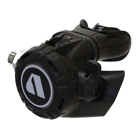
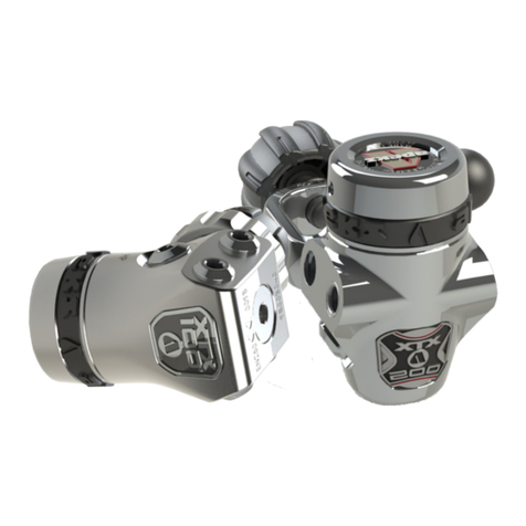
Apeks MTX-R User manual

TECHNICAL SUPPORT
APEKS MARINE EQUIPMENT LTD, NEPTUNE WAY, BLACKBURN, LANCASHIRE. BB1 2BT
MAINTENANCE MANUAL
FOR
AUTHORISED TECHNICIANS
Document No. AP5837
Issue 1
10/05/2017
MTX-R 2ND STAGE
REGULATOR

2
MTX-R 2nd Stage Maintenance Manual
AMENDMENTS RECORD:
Amendments and approval of this document can only be carried out by the relevant people listed on the Approved list of
signatures, which is listed in the Apeks Quality Manual. To instigate a change, a Task / Change request form, (Form No.
‘DESI/10002’), must be completed and passed to the relevant person(s) for approval which are listed on the Approved List of
Signatures. When approval has been granted and recorded this table can then be completed and the document up issued.
Change
No.
Change
Request No.
Description & Comments: Change
Date
New Issue
No.
Changed
By:
Approved
By:

3
MTX-R 2nd Stage Maintenance Manual
Contents
COPYRIGHT NOTICE............................................................................................................................................. 4
INTRODUCTION ..................................................................................................................................................... 4
WARNINGS, CAUTIONS & NOTES ...................................................................................................................... 4
SCHEDULED SERVICE ......................................................................................................................................... 4
HOSE INSPECTION & CLEANING PROCEDURE...............................................................................................4
GENERAL GUIDELINES........................................................................................................................................ 5
GENERAL CONVENTIONS ................................................................................................................................... 5
DISASSEMBLY PROCEDURES.............................................................................................................................5
REASSEMBLY PROCEDURES...............................................................................................................................9
FINAL TESTING.....................................................................................................................................................14
CONVERTING TO LEFT HAND CONFIGURATION...........................................................................................16
TABLE 1 - TROUBLESHOOTING GUIDE............................................................................................................19
TABLE 2 - RECOMMENDED TOOL LIST........................................................................................................... 20
TABLE 3 - RECOMMENDED LUBRICANTS AND CLEANERS ...................................................................... 21
TABLE 4 -TORQUE SPECIFICATIONS .............................................................................................................. 22
TABLE 5 - TEST BENCH SPECIFICATIONS ..................................................................................................... 22
CLEANING AND LUBRICATION PROCEDURE.................................................................................................23
EXPLODED PARTS DRAWINGS ........................................................................................................................ 24

4
MTX-R 2nd Stage Maintenance Manual
4
COPYRIGHT NOTICE
This manual is copyrighted, all rights reserved. It may not,
in whole or in part, be copied, photocopied, reproduced,
translated, or reduced to any electronic medium or machine
readable form without prior consent in writing from Apeks
Marine Equipment Ltd. It may not be distributed through the
internet or computer bulletin board systems without prior
consent from Apeks Marine Equipment Ltd.
©2017 Apeks Marine Equipment Ltd.
MTX-R 2nd Stage Regulator Maintenance Manual
(AP2017 Issue 1)
INTRODUCTION
This manual provides factory prescribed procedures for the
correct maintenance and repair of the Apeks MTX-R regulator.
It is not intended to be used as an instructional manual for
untrained personnel. The procedures outlined within this
manual are to be performed only by personnel who have
received factory authorised training through an Apeks Service
& Repair Seminar. If you do not completely understand all
of the procedures outlined in this manual, contact Apeks to
speak directly with a Technical Advisor before proceeding any
further.
SCHEDULED SERVICE
It is recommended that the Apeks MTX-R 2nd Stage
regulator should be examined annually regardless of
usage.
A full service should be performed every two years.
However, If you are at all unsure about the correct
functioning of the Apeks MTX-R 2nd Stage then it must be
ofcially inspected immediately.
All service and inspection details need to be documented
to keep the Limited Lifetime Warranty in effect.
A Second Stage Ofcial Inspection
consists of:
1. Checking the lever height with setting tool.
2. Checking for opening effort that is within the
acceptable range.
3. A pressurised immersion test of the entire unit to
check for air leakage.
4. A visual inspection of the exhaust valve(s) to see
that they are in good condition and that it is seating
against a clean and undamaged surface.
5. Pulling back hose protectors and checking that the
hoses are secure in the hose crimps.
6. A visual inspection of the mouthpiece looking for
tears or holes and checking the general condition.
If a regulator fails steps 1,2 or 3 the entire regulator should
be serviced. If a regulator fails step 4 it will be up to the
technician’s discretion whether or not a full service is
required. Failure of step 5 or 6 requires replacement of the
part.
HOSE INSPECTION & CLEANING
PROCEDURE
Please refer to the
seperate document
labelled “Hose Inspection
& Cleaning Procedure”
for full details of the
maintenance of hoses
which can be found in the
Technical section of the
Apeks website.
WARNINGS, CAUTIONS & NOTES
Pay special attention to information provided in warnings,
cautions, and notes that are accompanied by one of these
symbols:
WARNINGS indicate a procedure or situation
that may result in serious injury or death if
instructions are not followed correctly.
CAUTIONS indicate any situation or
technique that will result in potential
damage to the product, or render the
product unsafe if instructions are not
followed correctly.
NOTES are used to emphasise important
points, tips, and reminders.

5
MTX-R 2nd Stage Maintenance Manual
GENERAL GUIDELINES
1. In order to correctly perform the procedures outlined
in this manual, it is important to follow each step
exactly in the order given. Read over the entire
manual to become familiar with all procedures and
to learn which specialty tools and replacement parts
will be required before commencing disassembly.
Keep the manual open beside you for reference while
performing each procedure. Do not rely on memory.
2. All service and repair should be carried out in a work
area specically set up and equipped for the task.
Adequate lighting, cleanliness, and easy access to
all required tools are essential for an efcient repair
facility.
3. During disassembly, reusable components should be
segregated and not allowed to intermix with non-
reusable parts or parts from other units. Delicate
parts, including inlet ttings and valve seats which
contain critical sealing surfaces, must be protected
and isolated from other parts to prevent damage
during the cleaning procedure.
4. Use only genuine Apeks parts provided in the 2nd
stage service kit (AP0219). DO NOT attempt to
substitute an Apeks part with another manufacturer’s,
regardless of any similarity in shape or size.
5. Do not attempt to reuse mandatory replacement
parts under any circumstances, regardless of the
amount of use the product has received since it was
manufactured or last serviced.
6. When reassembling, it is important to follow every
torque specication prescribed in this manual,
using a calibrated torque wrench. Most parts are
made of either marine brass or plastic, and can be
permanently damaged by undue stress.
GENERAL CONVENTIONS
Unless otherwise instructed, the following terminology and
techniques are assumed:
1. When instructed to remove, unscrew, or loosen a
threaded part, turn the part anti-clockwise.
2. When instructed to install, screw in, or tighten a
threaded part, turn the part clockwise.
3. When instructed to remove an ‘O’ Ring, use the pinch
method (see gure below) if possible, or use a brass,
aluminium or plastic ‘O’ Ring removal tool. Avoid using
hardened steel picks, as they may damage ‘O’ Ring
sealing surfaces. All ‘O’ Rings that are removed are
discarded and replaced with brand new ‘O’ Rings.
4. The following acronyms are used throughout the
manual: MP is Medium Pressure; HP is High Pressure;
PN is Part Number.
5. Numbers in parentheses reference the key numbers
on the exploded parts schematics. For example, in
the statement, “...remove ‘O’ Ring (12) from...”, the
number 12 is the key number to the Blanking Piece ‘O’
Ring.
DISASSEMBLY PROCEDURES
NOTE: Before performing any disassembly,
refer to the exploded parts drawing, which
references all mandatory replacement parts.
These parts should be replaced with new, and
must not be reused under any circumstances
regardless of the age of the regulator or how
much use it has received since it was last
serviced.
CAUTION: Use only a plastic, brass or
aluminium ‘O’ Ring removal tool (PN AT79)
when removing ‘O’ Rings to prevent damage
to the sealing surface. Even a small scratch
across an ‘O’ Ring sealing surface could
result in leakage. Once an ‘O’ Ring sealing
surface has been damaged, the part must
be replaced with new. DO NOT use a dental
pick, or any other steel instrument.
Pinch Method
Press upwards
on sides of ‘O’
Ring to create a
protrusion. Grab
‘O’ Ring or insert
‘O’ Ring tool at
protrusion.

6
MTX-R 2nd Stage Maintenance Manual
NOTE: Ensure that
the pegs on the tool
fully engage on the
case cover whilst
unscrewing.
Removal of Hose Removal of Diaphragm
1. Using a 28mm spanner hold the Heat Exchanger
(9) stationary while turning the Hose Swivel
anticlockwise with a 11/16” spanner. Then using a
5mm Hex key and holding the hose swivel with the
11/16” spanner remove the Adapter Hose (33).
3. Pull back the two
Hose Protectors (31)
and inspect the Hose
Crimps. If either Crimp
is damaged or the
Hose is pulling out
of the crimp then the
Hose must be replaced.
5. Using the MTX-R Front Cover Tool (PN AT94),
unscrew the Case Cover (2).
NOTE: The Front Cover (2) and Purge Button
(1) should be cleaned complete. It is not
necessary to remove the purge button when
servicing.
Removal of Valve Assembly
6. Lift out the Diaphragm Cover (3) and Diaphragm
(4). Inspect the Diaphragm. It should be supple and
be free from damage. If it looks good, there is no
need to replace it and it may be reused. If there is any
sign of deterioration, it should be replaced.
7. Using an 28mm
spanner, remove the
Heat Exchanger (9).
2. Remove the ‘O’ Rings (15) from inside the Hose
Swivels on each end. Exercise caution not to scratch
the ‘O’ Ring groove. Remove the ‘O’ Ring (26) from
the Adapter Hose (33).
Removal of Mouthpiece
4. Using side cutters, snip the Tie Wrap (7) taking
care not to damage the Mouthpiece (8). Remove the
Mouthpiece.

7
MTX-R 2nd Stage Maintenance Manual
8. Press the Lever (19) against the Valve Spindle
(17). While keeping the Lever depressed, grasp the
Bumper (28) and pull the Valve Spindle assembly out
of the Case (6) or remove the Spindle by pushing on
the threaded end.
9. Remove the Blanking
Piece (11) and Venturi
assembly (13 & 14)
from the Case.
NOTE: The Venturi assembly may come out with
the valve Spindle in step 8. If this is the case,
depress the Lever and slide the Venturi Lever off.
11. Remove O ring (12)
from the Venturi Lever
assembly.
12. It is NOT necessary to separate the Venturi
assembly into its two separate parts unless the
regulator is being converted to a different hand
conguration. To separate them grasp the Venturi
assembly (13 & 14) and push the Venturi Blank (13)
off the Venturi Lever Body (14).
13. Remove the
Bumper (28) with a at
screwdriver.
15. Unscrew the
Adjusting Screw (27)
and completely remove
it from the Valve
Spindle (17).
16. Remove the ‘O’
Ring (26) from the
Adjusting Screw.
17. Remove the ‘O’
ring (10) from the Valve
Spindle (17).
10. Remove O rings (10
& 12) from the Blanking
Piece (11).
14. Turn the Adjusting Screw (27) clockwise (inward)
one turn using a 5mm Hex Key. The Spring Pin
(20) should drop out. If the Pin remains in the
Valve Spindle, use a 1/16” dowel or punch to push
it partially out, then use needle nose pliers to
completely remove it from the Valve Body.
18. Insert a small 1/8” wooden dowel or small Hex
key into the threaded end of the Valve Spindle (17)
and push out the Shuttle Valve assembly (21-25).
Separate the Shuttle Valve assembly by pulling on
each end.

8
MTX-R 2nd Stage Maintenance Manual
21. Using a Slotted Seat Adjuster (PN AT51/L), turn
the Seat (16) six to seven full turns anti-clockwise.
As the Seat is ‘O’ Ring sealed, it will not completely
unscrew from the Valve Spindle (17). Insert a pair of
external circlip pliers into the Valve Spindle (17), and
pull the Seat (16) completely out.
23. To remove the
Spindle Collar (18),
push both edges of the
collar as shown.
NOTE: It is not necessary to remove the Spindle
Collar (18) under normal servicing circumstances,
unless it is deemed relevant by the service
technician, for example if it is damaged or dirty.
This Ends Disassembly
Before starting reassembly, perform parts
cleaning and lubrication according to the
procedures outlined in ‘Cleaning & Lubrication’
on page 23.
NOTE: If the
Exhaust Valve (29)
is to be removed,
pinch the edge of
the Valve and pull
the tail through the
hole in the Case (6).
Inspection and Removal of Exhaust Valve
25. To remove the Exhaust Tees (30), depress the
retaining button located in the centre (see picture)
and slide the Left Hand Exhaust Tee off the Case (6).
Then slide the Right Hand Exhaust Tee off the case.
26. Fold back the edges of the Exhaust Valve (29)
and inspect underneath. The seating surface should
be clean and free of damage. Inspect the Exhaust
Valve. It should be supple and have well dened
edges. If it looks good, there is no need to remove
it and it may be reused. If there is any sign of
deterioration, it should be replaced.
22. Remove the ‘O’
Ring (15) from the Seat
(16).
NOTE: The Lever (19) should be inspected for
deterioration, it is NOT necessary to remove it
from the Valve Spindle (17), unless it is deemed
relevant by the service technician, for example if
it is damaged or mis-shaped.
24. To remove the
Lever (19) pull one
of the legs out of the
Valve Spindle (17) and
then ease the second
leg out.
19. Using a ngernail,
remove the Silicone
Seat (21) from the
shuttle valve (22).
20. Remove ‘O’ Ring
(23) from the shuttle
valve (22).

9
MTX-R 2nd Stage Maintenance Manual
Fitting Exhaust Valve and Exhaust Tees
WARNING: Flooding may occur if the tail of
the valve is not fully pulled through. Check
that barb has engaged on inside of Case.
1. If the Exhaust Valve (29) was removed, replace by
threading the tail through the retaining hole on the
outside of the Case (6) until the barb engages on the
inside. If the Exhaust Valve is new, cut off the excess
stem with side cutters leaving approximately 5mm of
the tail behind.
2. Check that the
Exhaust Rib is rmly
located in the Left Hand
Large Exhaust Tee.
3. Align the Left Hand
Exhaust Tee guide with
the slots on the Case
(6). Slide the Exhaust
Tee onto the Case until
the retaining button
is positioned centrally
over the Exhaust Valve
(29). Align the Right
Hand Exhaust Tee with
the Case and slide
into position until the
retaining button clips
underneath the Left
Hand Exhaust Tee.
Assembling and Fitting Valve Assembly
NOTE: Ensure Silicone Seat has been tted
ush with Shuttle Valve.
4. Install a new,
lubricated ‘O’ Ring (10)
onto the Valve Spindle.
(17).
5. Press a new,
lubricated ‘O’ Ring (23)
onto the stem of the
Shuttle Valve (22).
7. Fit the Valve Spring (24) onto the leading edge of
the Counterbalance Cylinder (25). Carefully guide
the stem of the Shuttle Valve assembly through the
Spring and into the Counterbalance Cylinder.
NOTE: The short
exhaust kit used
on the MTX-R
Octopus follows the
same procedure as
explained in step 3.
6. Press a new Silicone Seat (21) into the front of the
Shuttle Valve (22).
NOTE: Ensure the surface is clean and at when
pressing Shuttle Valve onto Silicone Seat.
REASSEMBLY PROCEDURES

10
MTX-R 2nd Stage Maintenance Manual
CAUTION: Ensure that Lever is not twisted
and that legs are parallel. The lever should
appear as that shown on the left, not as
shown on the right. If necessary, gently
squeeze legs together to straighten.
WARNING: Ensure that the Spindle Collar
is set in the correct position. Failure to do so

will result in a substantial loss of breathing
performance.
CAUTION: Ensure that the Spindle Collar
clicks rmly into position and that the entire
Valve Spindle Hole is visible.
9. If you removed the Lever (19), position the Valve
Spindle (17) so that the Lever Hole is to the left of the
centre line and the groove is to the right of the centre
line. (See photo below left). Insert the lever so that
it points to the right of the Valve Spindle, as shown
below.
10. Ensure that the Spindle Collar (18) is rotated
to the correct position for the required Hose
conguration.

NOTE: Ensure that the Lever has a full range
of movement and does not catch on the Valve
Spindle. Ensure that the spring can be seen
through the Valve Spindle Hole.
11. With the “feet” of the Shuttle Valve pointing
downward (away from the Lever) and the Lever
pointing straight up (perpendicular to the Valve
Spindle), insert the Valve assembly into the Valve
Spindle. Using your nger, press the Shuttle Valve
assembly all the way into the Valve Spindle.
12. Install a new,
lubricated ‘O’ Ring
(26) onto the Adjusting
Screw (27).
LEFT HANDED RIGHT HANDED
CAUTION: Do
not overstretch
the Spindle Collar
when replacing
doing so may
cause the Spindle
collar to crack
and break.
8. If the Spindle Collar
(18) was removed
during the disassembly
process ret the Collar
using a set of circlip
pliers. Spread the
Collar (18) and push it
onto the Valve Spindle
(17). Ensure that the
arrow points towards
the lever and the Collar
locates in the groove
on the Spindle (17).
LEVER
DIMPLE
CENTRE
LINE
LEVER
HOLE

11
MTX-R 2nd Stage Maintenance Manual
NOTE: The Arrow and line must be aligned
to ensure that the two parts fasten together
correctly. Ensure that the correct conguration of
regulator is selected. i.e. if the Regulator is to be
congured as Right Handed, then the arrow must
be aligned to the line with RIGHT underneath.
See the section titled Converting the MTX-R
Regulator to Left Handed Conguration on
page 16 for further information.
CAUTION: Ensure that the parts of the
Venturi Lever assembly are rmly pressed
together. There should be a step as shown in
the photo on the right above. An audible click
should be heard when pressing together.
15. If the Venturi Lever Body was separated slide the
Venturi Blank (13) onto the Venturi Lever Body (14).
Align the Arrow on the Venturi Blank above the letter
‘R’ with the line on the Venturi Lever Body above the
RIGHT text. Press the Venturi Blank rmly onto the
end of the Venturi Lever Body, until it clicks into place.
16. Install a new,
lubricated ‘O’ Ring (12)
onto the Venturi Lever
assembly. Point the
Venturi Lever assembly
upward and insert it into
the Case (6), on the
side marked RIGHT.
17. Install a new, lubricated ‘O’ Ring (12) onto the
Blanking Piece (11). Point the Blanking Piece upward
and insert it into the Case. Press it against the Case
so the ‘O’ ring is captured.
13. Install the Adjusting Screw into the Valve Spindle
using a 5mm Hex Key. There should now be spring
tension on the Lever. Continue to screw clockwise
until the holes for the Spring Pin are clear.
14. Install the Spring
Pin (20). Be sure that
it sits evenly in the
hole. Back the Screw
Adjuster (27) out anti-
clockwise to apply
tension on the Pin to
prevent it from falling
out.
LEFT RIGHT
RIGHT
R
L

12
MTX-R 2nd Stage Maintenance Manual
18. While depressing
the Lever, insert the
Valve Spindle through
the Venturi Lever
assembly and into the
Case.
CAUTION: Ensure
that the Lever
is vertical after
tightening.
CAUTION: Excessive
tightening of the
Heat Exchanger will
damage the Blanking
Piece and Case.
19. Slide a new, lubricated ‘O’ Ring (10) down the
threaded end of the Valve Spindle (17). Screw the
Heat Exchanger (9), widest hexagon side facing
outward, onto the Valve Spindle until nger tight.
22. Fit a new, lubricated
‘O’ Ring (15) onto the
Seat (16).
CAUTION: Ensure Diaphragm is seated
correctly and not creased.
Fitting Diaphragm
24. While holding the
rim of the case at eye
level, turn the seat
clockwise until the
lever drops about 4mm
below the case rim.
25. Position the Diaphragm (4) into the Case (6).
Using your nger, work the edges of the Diaphragm
into place so it sits evenly in the Case. Install
the Diaphragm Cover (3) into the Case, over the
Diaphragm.
CAUTION: Ensure
that the two ats
and the two Lever
feet engage in
the tabs of the
Blanking Piece.
21.Using an 28mm
crows foot, tighten the
heat exchanger to a
torque of 3 Nm (2.2 ft/
lb).
20. On the opposite adjustment side of the spindle
assembly, notice the two ats. Using a soft jaw vice,
clamp the whole second stage using the ats to avoid
the spindle turning within the case.
23. Press the Seat assembly threaded end rst
into the Valve Spindle (17). Using the Slotted Seat
Adjuster Tool (AT51/L), push the Seat into the Valve
Spindle as far as it will go.

13
MTX-R 2nd Stage Maintenance Manual
26. Screw the Case Cover (2) onto the Case. Using
the MTX-R Tool (AT94) tighten the Cover until it stops.
Conrm that the Purge Button is properly aligned.
Fitting Hose and Mouthpiece
WARNING:
Ensure that the
Mouthpiece is
properly secured
on the outlet port.
Before tting hose, carry out vacuum test by
holding thumb over Valve Spindle (17) to seal
and inhale through mouthpiece outlet port. No air
should be drawn in.
27. Add a new lubricated ‘O’ Ring (26) to the 3/8” end
of the Adapter Hose (33). Install new, lubricated ‘O’
Rings (15) into the hose swivel at both ends.
29. Fix the second stage into a soft jawed vice as
explained in section 20.
31. If equipped with a
Comfo-bite Mouthpiece,
make sure the ‘bridge’
of the Mouthpiece
(8) is facing upward.
Stretch the Mouthpiece
over the second-stage
Mouthpiece outlet
port. At the base of the
Mouthpiece is a groove
for the Tie Wrap (7).
Tighten the Tie Wrap so
that the buckle points
toward the Hose. Snip
the excess with side
cutters.
NOTE: If your facility is equipped with a test
bench, perform the tests before installing the
mouthpiece. General instructions for performing
bench tests are located in the next section “Final
Testing.”
32. After all testing has
been completed, ret
the Bumper (28) onto
the Spindle (17).
This Completes Assembly
30. Screw the Hose
onto the second
stage. Using an 11/16”
crowsfoot and torque to
5Nm (3.7 ft/lb).
28. Screw the Adapter
Hose (33) into one end
of the hose (32). Hold
the hose swivel with
an 11/16” spanner and
torque to 5Nm (3.7 ft/
lb) using a 5mm Hex
Key Bit.
NOTE: If air is drawn in refer to trouble
shooting guide.

14
MTX-R 2nd Stage Maintenance Manual
FINAL TESTING
Setting the Lever Height
2. Screw the Inline
Adjustment Tool onto
the threaded end of the
2nd stage. Attach the
rst stage to a cylinder
containing 207 Bar
(3000 psi). Slowly open
the cylinder valve and
pressurise the reguator.
3. Purge the 2nd stage 2
to 3 times to check there
is air ow.
1. Attach an Inline
Adjustment Tool (AT72)
to a regulator hose
on a correctly set rst
stage. Refer to the
appropriate rst stage
technical manual before
attempting to perform
any adjustments.
4. Strike the purge
button again 3 times to
check there is no free
ow. If the 2nd stage
does freeow check
the following 3 notes to
determine the reason.
5. Place the “GAS FLOW” side of the testing puck
section on the Front Cover Tool (AT94) over the purge
button.There should be a ow of air, if not adjust the
inline adjuster counter clockwise in 1/16 turns until
there is a steady ow.
NOTE:It is important to ensure that the rim of
the tool is concentric with the rim of the purge
button throughout. Pressing on the logo with the
tool misaligned will not measure the purge button
depth and therefore give incorrect results.
NOTE: If there is gas ow, keep the puck on
“NO GAS FLOW” and turn the inline adjuster
clockwise in 1/16 increments until the ow
ceases. Turn the puck back to “GAS FLOW” to
make sure there is still air ow.
Warning:Compressed air can be highly
explosive and is dangerous if misused.
Ensure cylinder valve is opened slowly. Use
eye and ear personal protective equipment
when performing any tests involving
compressed air.
6. Turn the puck section
of the adjustment tool to
the opposite side “NO
GAS FLOW” to check
that the lever is set
correct and there is no
ow of air.
NOTE: If the 2nd
stage is leaking
turn the inline
adjuster clockwise
until the leaking
stops.
NOTE: Check that the two ats and the two
Lever feet engage in the tabs of the Blanking
Piece. Refer to step 18 on page 12.
NOTE: Check that the Venturi lever body is lined
up with the venturi blank. Refer to step 15 on
page 11.
NOTE: Check the lever is vertical. Refer to steps
20 & 21 on page 12
CAUTION: The air ow should be continuous
with no uttering
NOTE: Keep the puck in place whilst making
adjustments
CAUTION: Free ow test should be done
every time the lever height has been adjusted.
NO GAS
MTX/ATX
NOTE: “NO GAS” will be visible when performing
gas ow setting.
GAS
MTX/ATX
NOTE: “GAS” will be visible on the tool when
checking no gas ow.

15
MTX-R 2nd Stage Maintenance Manual
This Ends Final Testing
Second Stage Opening Effort Test
1. Connect the rst stage regulator with an interstage
pressure gauge tted to a calibrated test bench and
pressurise the system to 207 bar. Fit the 2nd stage
onto the Magnehelic mouth piece connector. Slowly
open the owmeter control knob (start vacuum)
while watching both the magnahelic gauge and the
intermediate pressure gauge.
2. When the intermediate pressure begins to drop,
indicating the second-stage valve is open, the
magnahelic gauge should indicate an opening effort
of +1.9 in.H2O (4.7 mbar) to +2.1 in.H2O (5.2 mbar).
If the reading is outside of these specications, adjust
the Screw Adjuster (27), turning clockwise to increase
the opening effort or anti-clockwise to lower the
opening effort. If this fails to give the correct reading
refer to “Table 1 - Troubleshooting” for corrective
actions.
External Leak Test
1. After disconnecting the regulator from the
ow bench, connect it to a gas cylinder lled to
approximately 200 bar. Open the cylinder valve to
repressurise the regulator, and submerge the entire
system in a test tank of clean water.
2. Observe any bubbles arising from the
submerged regulator over a one minute period.
The recommended time is necessary due to slower
bubble formation that occurs in smaller leaks. Bubbles
indicate a leak, which requires the system to be
disassembled at the source to check sealing surfaces,
assembly sequence and component positioning in
order to correct the problem(s).
NOTE: Extremely small leaks may be better
detected by applying a soap solution or Snoop™
to the leak area. Bubble streams will indicate
the source of the leak. Before disassembling
to correct any leaks, rinse the entire regulator
thoroughly with fresh water and blow out all
residual moisture with ltered, low-pressure air.
Disassemble and remedy the problem, referring
to “Table 1 - Troubleshooting.”
Subjective Breathing Test
Depress the Purge Button fully to ensure that an
adequate volume of air needed to clear the second
stage ows through the mouthpiece. Then, inhale
slowly but deeply from the mouthpiece. A properly
serviced and adjusted regulator should deliver air upon
deep inhalation without excessive inhalation effort,
freeow, or “uttering” of the second-stage diaphragm.
When exhaling, there should be no uttering or sticking
of the exhalation valve. If any of these problems occur,
refer to “Table 1 - Troubleshooting”.
3. With the 2nd stage
still attached to the
Magnehelic mouthpiece,
turn the air supply off,
the vacuum gauge
should read above
100mm Hg (53.5” of
water).
NOTE: If the Magnehelic being used isn’t tted
with a vacuum gauge you will need to perform
the test orally. Place your thumb over the
inlet tting and inhale in normally through the
mouthpiece. If you can draw air in or hear air ow
refer to the trouble shooting guide on page 19.
NOTE: The image
shows the 1st
stage attached to
a high pressure
extension and not a
cylinder.

16
MTX-R 2nd Stage Maintenance Manual
CONVERTING THE MTX-R REGULATOR
TO LEFT HANDED CONFIGURATION
NOTE: Ensure that the tool is rmly pressed
against the Case Cover whilst unscrewing.
NOTE: The Venturi Lever assembly may have
come out with the valve Spindle in step 4. If this is the
case, depress the Lever and slide the Venturi Lever
assembly from the spindle.
Right Handed
Conguration
Left Handed
Conguration
1. Using a 28mm
spanner hold the
Heat Exchanger (9)
stationary while turning
the Hose Swivel anti-
clockwise with a 11/16”
spanner.
3. Using an 28mm
spanner, remove the
Heat Exchanger (9).
2. Using the Tool (AT94), unscrew the Case Cover
(2). Lift out the Diaphragm Cover (3) and Diaphragm
(4).
4. Press the Lever (19) against the Valve Spindle
(17). While keeping the Lever depressed, grasp the
Bumper (28) and pull the Valve Spindle assembly out
of the Case (6) or remove the Spindle by pushing on
the threaded end.
6. Grasp the Venturi Lever
Assembly (13 & 14) and
pull it out of the Case.
Remove the ‘O’ Ring (12)
from the assembly
5. Remove the two ‘O’
Rings (10) & (12) from the
Blanking Piece (11).
7. Grasp the Venturi
Lever Assembly (13 &
14) as shown and push
the Venturi Blank (13)
to separate it from the
Venturi Lever Body (14).
LEFT
NOTE: The Arrow and line must be aligned to ensure
that the two parts fasten together correctly. Ensure that
the correct conguration of regulator is selected. i.e.
if the Regulator is to be congured as Left Handed,
then the arrow must be aligned to the line with LEFT
underneath.
8. Rotate the Venturi Blank (13) on the Venturi Lever Body
(14). Align the Arrow below the letter ‘L’ on the Venturi
Blank with the line on the Venturi Lever Body above the
LEFT text. Press the Venturi Blank rmly onto the end of
the Venturi Lever Body, until it clicks into place.
R
L

17
MTX-R 2nd Stage Maintenance Manual
CAUTION: Ensure that the parts of the
Venturi Lever assembly are rmly pressed
together. There should be a step as shown in
the photo on the right below. An audible click
should be heard when pressing together. WARNING: Ensure that the spindle collar is
set in the correct position. Failure to do so
will result in a substantial loss of breathing
performance. The photo below shows the
Valve Spindle in both the Left and Right hand
congurations.
CAUTION: Ensure that the Spindle Collar
clicks rmly into position and that the entire
Valve Spindle Hole is visable.
LEFT HANDED RIGHT HANDED
LEFT RIGHT
15. On the opposite adjustment side of the spindle
assembly, notice the two ats. Using a soft jaw vice,
clamp the whole second stage using the ats to avoid
the spindle turnng within the case.
9. Install a new lubricated
‘O’ Ring (12) onto the
Venturi Lever assembly.
14. Slide a new lubricated ‘O’ Ring (10) down the threaded
end of the Valve Spindle (17). Screw the Heat Exchanger
(9), hexagon facing outward, onto the Valve Spindle until
nger tight.
13. While depressing the Lever, insert the Valve Spindle
through the Venturi Lever assembly and into the Case. Be
sure that the two ats and the two Lever feet engage in the
tabs of the Blanking Piece.
12. Rotate the Spindle Collar (18) on the Valve Spindle (17)
until it clicks into position. The Valve Spindle should look
like the photo on the right.
11. Install a new lubricated ‘O’ Ring (12) onto the Blanking
Piece (11). Point the Blanking Piece upward and insert it
into the Case on the side marked “RIGHT” (6). Press it
against the Case so the ‘O’ Ring is captured.
10. Point the Venturi Lever Assembly upward and insert it
into the side of the Case (6) marked ‘LEFT’. Press it against
the Case so the ‘O’ ring is captured.

18
MTX-R 2nd Stage Maintenance Manual
CAUTION: Ensure Diaphragm is seated
correctly and not creased.
Before tting hose, carry out vacuum test by
holding thumb over Valve Spindle (17) to seal and
trying to breathe through mouthpiece outlet port.
No air should be inhaled.
This Ends the Conversion Procedure,
Proceed to Final Testing
NOTE: If your facility is equipped with a test bench,
remove the mouthpiece as described on page 6.
General instructions for performing bench tests are
located in the section, “Final Testing” on page 14.
CAUTION: Excessive tightening of the Heat
Exchanger will damage the Blanking Piece
and Case.
16.Using an 28mm
crows foot, tighten the
Heat Exchanger (9) to
a torque of 3 Nm (2.2
ft/lb).
CAUTION: Ensure that the Lever is vertical
after tightening.
20. Fix the second stage into a soft jawed vice as
explained in section 15.
21. Screw the Hose
onto the second
stage. Using an 11/16”
crowsfoot and torque to
5Nm (3.7 ft/lb).
18. Position the Diaphragm (4) into the Case (6). Using
your nger, work the edges of the Diaphragm into place so
it sits evenly in the Case . Install the Diaphragm Cover (3)
into the Case, over the Diaphragm.
17. Ensure the Valve
Spindle hole points to the
top of the case.
19. Screw the Case Cover (2) onto the Case (6). Using
Tool AT94 tighten the Cover until it stops. Conrm that the
Purge Button is properly aligned.

19
MTX-R 2nd Stage Maintenance Manual
SYMPTOM POSSIBLE CAUSE TREATMENT
Leakage or freeow
from Second Stage
1. Excessively high rst-stage intermediate
pressure.
1. Refer to rst-stage Troubleshooting
Guide.
2. Silicone Valve Seat (21) damaged or
worn. 2. Replace Silicone Seating.
3. Seat (16) adjusted incorrectly, Lever (19)
set too high.
3. Reset Seat preliminary settings, and
repeat Adjustment Procedures.
4. Lever (19) bent. 4. Replace Lever.
5. Seat (16) sealing surface damaged. 5. Replace Valve Seat.
6. Valve Spring (24) damaged. 6. Replace Spring.
7. Shuttle Valve ‘O’ Ring (23) damaged. 7. Replace ‘O’ Ring.
8. Counter Balance Cylinder (25) bore
damaged. 8. Replace Counter Balance Cylinder.
Low purge or
excessive work
of breathing (full
cylinder)
1. Low rst-stage intermediate pressure. 1. Refer to rst-stage Troubleshooting
Guide.
2. Seat (16) adjusted incorrectly, Lever (19)
set too low.
2. Reset Seat preliminary settings, and
repeat Adjustment Procedures.
3. Intermediate pressure hose clogged or
obstructed. 3. Clean or replace Hose.
4. Lever (19) bent or catching on Valve
Spindle (17). 4. Replace Lever.
5. Spindle Collar (18) incorrectly positioned
on Valve Spindle (17).
5. Rotate Spindle Collar to correct
position.
Water entering
Second Stage or
Vacuum test failure
1. Mouthpiece (8) damaged or incorrectly
tted.
1. Replace or re-t Mouthpiece as
appropriate.
2. Diaphragm (4) damaged. 2. Replace Diaphragm.
3. Diaphragm (4) improperly seated in Case
(6).
3. Remove Front Cover (2) and Diaphragm
Cover (3) properly reassemble
Diaphragm (check for distortion).
4. Exhaust Valve (29) damaged. 4. Replace Exhaust Valve.
5. Case (6) damaged. (Check exhaust valve
seating surface.) 5. Disassemble and replace Case.
6. Heat exchanger (9) or Spindle (17) ‘O’
Ring (10) damaged. 6. Replace ‘O’ Ring.
7. Venturi Lever assembly or Blanking Piece
(11) ‘O’ Ring (12) damaged. 7. Replace ‘O’ Ring.
Table 1 - Troubleshooting Guide

20
MTX-R 2nd Stage Maintenance Manual
PART # DESCRIPTION APPLICATION IMAGE
AT79 O Ring Removal Pick O Ring Removal
AT94 Front Cover Tool Case Cover Removal and Installation /
Setting of Lever Height
AT51/L Slotted Seat Adjuster Removal and Instalation of Seat
N/A Torque Wrench Nm or lb/ft Hose and Heat Exchanger
N/A 11/16” Adapter for Torque Wrench Hose
AT34 11/16” Spanner Hose
AT37 5mm Hex Key Removal and Installation of Screw
Adjuster and Adapter Hose
N/A Flat Screwdriver Removal of Bumper
N/A Side Cutters Tie Wrap and Exhaust Valve
AT24 Internal Circlip Pliers Seat Removal and Spindle Collar Fitting
AT72 Inline Adjustment Tool Setting Lever Height
N/A 28mm Spanner Heat Exchanger Removal
N/A 28mm Crow’s Foot Wrench Heat Exchanger Fitting
N/A 232 or 300 Bar Diving Cylinder Final Testing
Table 2 - Recommended Tool List
Other manuals for MTX-R
1
Table of contents
Other Apeks Controllers manuals

Apeks
Apeks XL4 SECOND STAGE User manual

Apeks
Apeks Egress User manual

Apeks
Apeks Flight User manual

Apeks
Apeks TX100 User manual

Apeks
Apeks FSR Series User manual

Apeks
Apeks GX300 User manual

Apeks
Apeks ATX Second Stage User manual

Apeks
Apeks XTX FSR User manual

Apeks
Apeks TEK3/XTX50 User manual

Apeks
Apeks DST User manual
Popular Controllers manuals by other brands

FASAR ELETTRONICA
FASAR ELETTRONICA FE1052 manual

oventrop
oventrop Aktor M technical information

LevelOne
LevelOne WAB-8011 Quick installation guide

Extron electronics
Extron electronics MEDIALINK MLC 52 Series quick start guide

Adaptec
Adaptec ASR-2045 Important information about issues and errata

BION TECHNOLOGIES
BION TECHNOLOGIES cambium xl user manual