Gewiss Chorus GW 90 740 User manual

GW 90 740
Attuatore 4 canali 16A EIB - da guida DIN
4 channel 16A EIB actuator - DIN rail
Actionneur 4 canaux 16A EIB - sur rail DIN
Actuador de 4 canales 16A EIB - de guía DIN
4-Kanal Antrieb 16A EIB - für DIN-Hutschiene

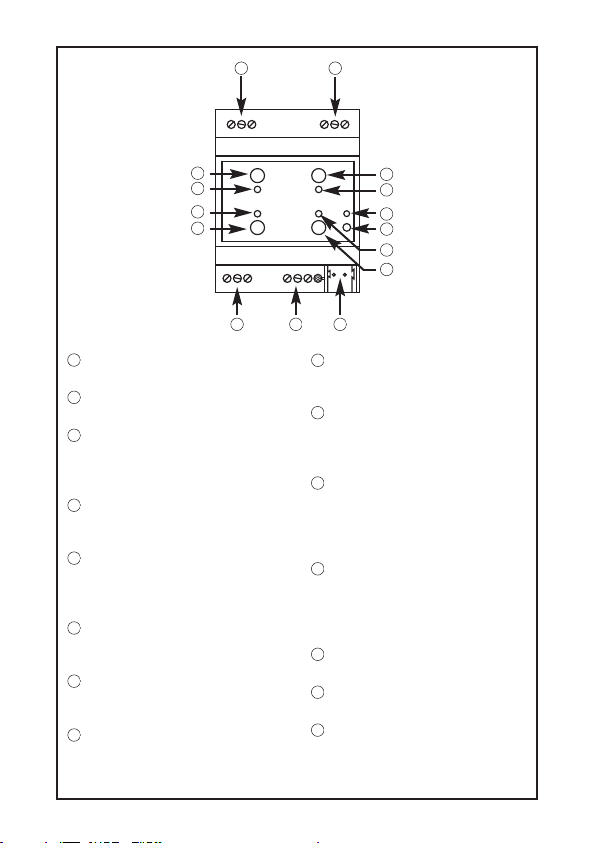
Uscita relè 1 -Output relay 1 - Sortie relais 1
-Salida relé 1 - Relaisausgang 1
Uscita relè 2 -Output relay 2 - Sortie relais 2
-Salida relé 2 - Relaisausgang 2
Pulsante attuazione locale relè 1 -Relay 1
local actuator button - Bouton actionnement
local relais 1 - Pulsador actuación local de relé
1 - Taste lokale Betätigung Relais 1
LED stato relè 1 -Relay 1 status LED - LED
état du relais 1 -LED de estado de relé 1 - LED
Status Relais 1
Pulsante attuazione locale relè 2 -Relay 2
local actuator button - Bouton actionnement
local relais 2 - Pulsador actuación local de relé
2 - Taste lokale Betätigung Relais 2
LED stato relè 2 -Relay 2 status LED - LED
état du relais 2 - LED de estado de relé 2 -
LED Status Relais 2
LED stato relè 3
-
Relay 3 status LED - LED
état du relais 3 - LED de estado de relé 3 -
LED Status Relais 3
Pulsante attuazione locale relè 3
-
Relay 3
local actuator button - Bouton actionnement
local relais 3 - Pulsador actuación local de relé
3 - Taste lokale Betätigung Relais 3
LED stato relè 4 -Relay 4 status LED - LED
état du relais 4 - LED de estado de relé 4 -
LED Status Relais 4
Pulsante attuazione locale relè 4 -Relay 4
local actuator button - Bouton actionnement
local relais 4 - Pulsador actuación local de relé
4 - Taste lokale Betätigung Relais 4
LED di programmazione indirizzo fisico -
Physical address programming LED - LED de
programmation adresse physique - LED de
programación de dirección física - LED für
Programmierung physikalische Adresse
Tasto di programmazione indirizzo fisico -
Physical address programming button - Touche
de programmation adresse physique - Tecla de
programación de dirección física - Taste für
Programmierung physikalische Adresse
Uscita relè 3 -Output relay 3 - Sortie
relais 3 - Salida relé 3 - Relaisausgang 3
Uscita relè 4 -Output relay 4 - Sortie
relais 4 - Salida relé 4 - Relaisausgang 4
Terminali bus -Bus terminals - Borniers
bus - Terminales bus - Busanschlüsse
2
1
3
4
5
5
1
6
7
8
3
6
4
7
8
11
2
13 14 15
12
9
10
9
10
11
12
13
14
15

INDICE
I
T
A
L
I
A
N
O
3
pag.
DESCRIZIONE GENERALE ..................................................................................... 4
INSTALLAZIONE.................................................................................................... 6
PROGRAMMAZIONE CON SOFTWARE ETS ........................................................... 8
DATI TECNICI........................................................................................................ 9

DESCRIZIONE GENERALE
4
L’Attuatore 4 canali 16 A EIB – da guida DIN permette di attivare/disattivare
indipendentemente fino a 4 diversi carichi elettrici attraverso 4 relè da 16 A provvisti di
1 contatto di uscita NA ciascuno.
Il comando di commutazione del relè può giungere da dispositivi di comando o sensori
del sistema di Building Automation, tramite il bus KNX/EIB, oppure essere generato
localmente mediante i pulsanti frontali.
L’attuatore è alimentato dalla linea bus ed è dotato di 4 LED frontali verdi per la
segnalazione di stato delle uscite. Il dispositivo invia sul bus informazioni sullo stato del
relè (ON = contatto NA chiuso, OFF = contatto NA aperto) all’accensione, alla ricezione
di un comando ed in caso di azionamento manuale.
Funzioni
L’attuatore viene configurato con il software ETS per realizzare le funzioni elencate qui
di seguito.
Commutazione:
- parametrizzazione comportamento uscite (NA/NC)
- temporizzazione luci scale con possibilità di impostare la durata della temporizzazione
via bus
- temporizzazione luci scale con funzione di preavviso allo spegnimento
- ritardo all’attivazione/disattivazione
- lampeggio
Scenari:
- memorizzazione ed attivazione di 8 scenari (valore 0-63) per ogni uscita
- abilitazione/disabilitazione memorizzazione scenari da bus
Comandi prioritari:
- parametrizzazione del valore relè di uscita al termine della forzatura
Comando di blocco:
- parametrizzazione valore oggetto di blocco e valore relè di uscita alla fine del blocco
Funzioni di sicurezza:
- monitoraggio periodico oggetto di ingresso

DESCRIZIONE GENERALE
I
T
A
L
I
A
N
O
5
Funzioni logiche:
- operazione logica AND/NAND/OR/NOR con oggetto di comando e risultato
operazione logica
- operazioni logiche AND/NAND/OR/NOR/XOR/XNOR fino a 4 ingressi logici
Stato uscita:
- invio su bus parametrizzabile
Altre funzioni:
- parametrizzazione comportamento uscita alla caduta/ripristino tensione su bus
- parametrizzazione comportamento tasti di comando locale
- parametrizzazione priorità fra oggetti di ingresso
Schema connessioni
-+
-
+
bus
U
L
N.A.
U
L N.A.
U
L
N.A. LN.A.
U
NN
NN

INSTALLAZIONE
6
ATTENZIONE: l’installazione del dispositivo deve essere effettuata
esclusivamente da personale qualificato, seguendo la normativa
vigente e le linee guida per le installazioni KNX/EIB, che sono riportate
nel Manuale Tecnico
Montare l’attutatore su guida DIN da 35 mm come mostrato in figura.
Montaggio su guida DIN
1
2

INSTALLAZIONE
I
T
A
L
I
A
N
O
7
Distanza minima bus - linea elettrica
Connessioni elettriche
Bus
230 V
≥ 4 mm
Fissaggio morsetto ad innesto

PROGRAMMAZIONE CON SOFTWARE ETS
8
Il dispositivo deve essere configurato con il software ETS.
Informazioni dettagliate sui parametri di configurazione e sui loro valori sono contenute
nel Manuale Tecnico.

DATI TECNICI
I
T
A
L
I
A
N
O
9
Comunicazione Bus KNX/EIB
Alimentazione Tramite bus KNX/EIB, 29 V dc SELV
Cavo bus KNX/EIB TP1
Assorbimento corrente dal bus 10 mA max
Elementi di comando 1 tasto miniatura di programmazione
4 pulsanti di comando locale dei relè
Elementi di visualizzazione 1 LED rosso di programmazione
4 LED verdi di segnalazione stato uscita
Elementi di attuazione 4 relè 16 A con contatto NA libero da tensione
Corrente max di commutazione 16 A (AC1)
16AX (140 μF rif. EN 60669-1) carichi fluorescenti
con corrente massima di spunto 400A (200 μs)
Potenza max per tipologia carico Lampade a incandescenza (230Vac): 3000W
Lampade alogene (230Vac): 3000W
Carichi pilotati da trasformatori toroidali: 3000W
Carichi pilotati da trasformatori elettronici: 2000W
Lampade a basso consumo
(fluorescenti compatte): 80x23W
Potenza massima dissipata 4W
Ambiente di utilizzo Interno, luoghi asciutti
Temperatura di funzionamento -5 ÷ +45 °C
Temperatura di stoccaggio -25 ÷ +70 °C
Umidità relativa Max 93% (non condensante)
Connessione al bus Morsetto ad innesto, 2 pin Ø 1 mm
Connessioni elettriche Morsetti a vite, sezione max cavi: 2,5 mm2
Grado di protezione IP20
Dimensione 4 moduli DIN
Riferimenti normativi Direttiva bassa tensione 2006/95/CE
Direttiva compatibilità elettromagnetica 89/336/CEE
EN50428, EN50090-2-2
Certificazioni KNX/EIB


CONTENTS
11
E
N
G
L
I
S
H
page
GENERAL DESCRIPTION....................................................................................... 12
INSTALLATION ...................................................................................................... 14
PROGRAMMING WITH ETS SOFTWARE................................................................ 16
TECHNICAL DATA ................................................................................................. 17

GENERAL DESCRIPTION
12
The 4 channel 16 A EIB Actuator – DIN rail allows you to individually activate/
deactivate up to 4 different electrical loads using 4 16 A relays fitted with 1 NO output
contact each.
The relay switching command can be given by Building Automation control or sensor
devices using the KNX/EIB bus, or they can be generated locally using the front buttons.
The actuator is powered by the bus line and is fitted with 4 front green LEDs which
indicate the output status.
This device sends the bus information on the relay status (ON = NO contact closed,
OFF = NO contact open) on the ignition, the reception of a command and when they
are activated manually.
Functions
The actuator is configured by the ETS software to achieve one of the functions listed
below.
Switching:
- output behaviour setting (NO/NC)
- timing of stairway lights with option to set the length of the time via bus
- timing of stairway lights with off prewarning function
- activation/deactivation delay
- flashing
Scenes:
- memorising and activation of 8 scenes (value 0-63) for each output
- enabling/disenabling memorising of scenes via bus
Priority controls:
- setting of output relay value parameters at the end of a forced command
Block command:
- setting of the blocked object value and the output relay value at the end of the block
Safety functions:
- periodic monitoring of input object

GENERAL DESCRIPTION
13
E
N
G
L
I
S
H
Logic functions:
- AND/NAND/OR/NOR logic operations with command object and logic operation result
- AND/NAND/OR/NOR/XOR/XNOR logic operations up to 4 logic inputs
Output status:
- Sending to bus with settable parameters
Other functions:
- Output behaviour setting during bus blackout/reinstatement
- local command buttons behaviour settings
- priority settings for input objects
Connection diagram
-+
-
+
bus
U
L
N.O.
U
L N.O.
U
L
N.O. LN.O.
U
NN
NN

INSTALLATION
14
WARNING: only qualified personnel are permitted to install this device,
according to the regulations in force and guidelines provided for
KNX/EIB installation in the Technical Manual.
Assemble the actuator onto a 35 mm DIN rail as shown in the drawing.
Assembly on a DIN rail
1
2

INSTALLATION
15
E
N
G
L
I
S
H
Minimum bus distance – electrical power line
Electrical connections
Bus
230 V
≥ 4 mm
Slot in terminal fixing

PROGRAMMING WITH ETS SOFTWARE
16
This device must be configured using the ETS software.
Detailed information on the configuration parameters and their values can be found in the
Technical Manual.

TECHNICAL DATA
17
E
N
G
L
I
S
H
Communication KNX/EIB Bus
Power Supply By KNX/EIB Bus, 29 V dc SELV
Bus cable KNX/EIB TP1
Bus current consumption 10 mA max
Control elements 1 mini programming key,
4 relay local command buttons
Display elements 1 red programming LED and
4 green output status signal LEDs
Actuator elements 4 NO 16 A relays with potential free contact
Max switching current 16 A (AC1)
16AX (140 μF rif. EN 60669-1) fluorescent lamps,
max peak in rush current of 400A (200 μs)
Max power for load type Incandescent lamps (230Vac): 3000W
Halogen lamps (230Vac): 3000W
Load controlled by toroidal transformer: 3000W
Load controlled by electronic transformer: 2000W
Lamps energy saver (compact fluorescent): 80x23W
Power dissipation (max) 4W
Ambit of use Indoors, dry places
Operating temperature -5 ÷ +45 °C
Storage temperature -25 ÷ +70 °C
Relative humidity Max 93% (no condensation)
Bus connection Slot in terminal, 2 pin Ø 1 mm
Electrical connections Screw terminals, max cable width: 2.5 mm2
Protection rating IP20
Dimensions 4 DIN modules
Reference standards Low Voltage Standard 2006/95/CE Electromagnetic
Compatibility Standard 89/336/CEE EN50428,
EN50090-2-2
Certifications KNX/EIB


SOMMAIRE
19
F
R
A
N
Ç
A
I
S
page
DESCRIPTION GENERALE..................................................................................... 20
INSTALLATION ...................................................................................................... 22
PROGRAMMATION AVEC LOGICIEL ETS............................................................... 24
DONNEES TECHNIQUES ....................................................................................... 25

DESCRIPTION GENERALE
20
L’Actionneur 4 canaux 16 A EIB – sur rail DIN permet d’activer / désactiver
indépendamment jusqu’à 4 charges électriques différentes, grâce à 4 relais de 16 A
munis d’1 contact de sortie NO chaque.
La commande de commutation du relais peut arriver de dispositifs de commande ou de
capteurs du système de Building Automation, grâce au bus KNX/EIB, ou bien être
engendré localement grâce aux boutons frontaux.
L’actionneur est alimenté par la ligne bus et est équipé de 4 LED frontales vertes pour
indiquer l’état des sorties.
Le dispositif envoie sur le bus des informations sur l’état du relais (Marche = contact NO
fermé, Arrêt = contact NF ouvert) au moment de l’allumage, au moment de la réception
d’une commande, et en cas d’actionnement manuel.
Fonctions
L’actionneur est configuré avec le logiciel ETS pour réaliser les fonctions énumérées ci-
après.
Commutation :
- paramétrisation du comportement des sorties (NO/NF)
- temporisation des lumières escalier, avec possibilité de régler la durée de la
temporisation via bus
- temporisation des lumières escalier, avec fonction de préavis avant l’extinction
- retard de l’activation / désactivation
- clignotement
Scénarios :
- enregistrement en mémoire et activation de 8 scénarios (valeur 0-63) pour chaque sortie
- activation /désactivation de la mémorisation des scénarios par bus
Contrôles prioritaires :
- paramétrisation de la valeur des relais de sortie à la fin du forçage
Commande de blocage :
- paramétrisation de la valeur objet de blocage et de la valeur du relais de sortie à la fin
du blocage
Fonctions de sécurité :
- monitorage périodique objet d’entrée
Table of contents
Languages:
Other Gewiss Controllers manuals

Gewiss
Gewiss Chorus GW 10 766 User manual

Gewiss
Gewiss Chorus GW 10 801 User manual

Gewiss
Gewiss Chorus GW 10 767 User manual

Gewiss
Gewiss Chorus GWA1521 User manual

Gewiss
Gewiss Chorus GW 90 856 User manual

Gewiss
Gewiss CHORUS GWA9140 User manual

Gewiss
Gewiss Chorus GW 90 852 User manual

Gewiss
Gewiss Chorus GW 10 568 User manual

Gewiss
Gewiss GW96 752 User manual

Gewiss
Gewiss Chorus GW 90 836A User manual