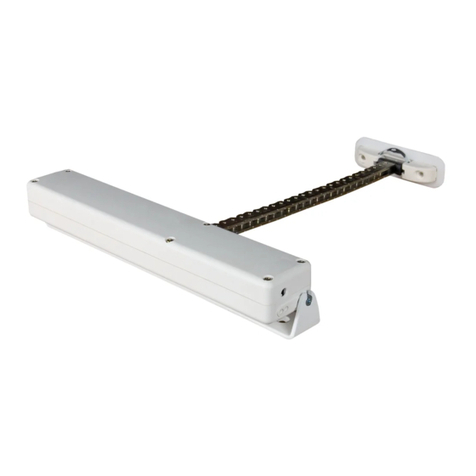
fakro ZWS12 User manual

User manual for actuator ZWS12
Contents
1. Safety standards .................................................................................................................................2
2. Description ........................................................................................................................................3
3. Programming the appliance................................................................................................................4
4. Association Groups............................................................................................................................5
5. Compati ility of other producers’ appliances in Z-Wave. ................................................................5
6. Z-Wave configuration parameters.....................................................................................................5
7. Alarms and Notifications...................................................................................................................6
8. Technical parameters..........................................................................................................................6
9. Command classes...............................................................................................................................6
10. Manufacturer Specific Report..........................................................................................................7
11. Description of signals – light – emitting diode (LED).....................................................................7
12. Warranty...........................................................................................................................................8
FAKRO Sp. z o.o.
ul. Węgierska 144A
33-300 Nowy Sącz
Polska
www.fakro.com
tel. 48 18 444 0 444
fax. +48 18 444 0 333
02.03.18 NC817-GB 1/8 ©2018, FAKRO
GB

1. Safety standards
Please carefully read the instructions below before installing the actuator to avoid electric
shocks laceration etc.
While installing the electric actuator it is essential to comply with the following rules:
Firstly, after unpacking, check that the actuator does not show any signs of mechanical
damage.
Installation should e performed y a qualified person according to the producer’s user
manual.
Before connecting the actuator, make sure that the supporting voltage is compati le with
the voltage of the actuator mentioned on the rated plate.
Connect the actuator and launch one cycle of work to verify whether it works correctly
(dual-core wire - 15V DC).
Plastic containers used for packing should e kept out of children’s reach as they pose a
potential threat.
The actuator should e used only for its purpose. FAKRO is not responsi le for any
damage of the actuator resulting from improper use.
Any actions related to cleaning, adjusting or disassem ling of the electric actuator should
e preceded y disconnecting the power supply.
Do not use any solvent-like agents, or a water jet (do not dip in water).
All repairs should e made y a service authorized y the producer.
The actuator is for external use only.
02.03.18 NC817-GB 2/8 ©2018, FAKRO

2. Description
ZWS12 actuators are only for external installation with Fakro roof windows. They are compati le with Fakro
wireless remote controls or other remote controls marked with the Z-Wave logo produced y other companies. actuators
are equipped with a two-way module of radio communication. Z-Wave uses 869 MHz radio waves.
The ZWS motors are equipped with two limit switches:
–limit switch at maximum chain travel position,
–overload limit in oth directions (used mainly when closing the window).
In order to use the appliance, it is essential to install it in accordance with the figure manual attached to its package.
Programming should e done with any of the remote controls availa le from Fakro or any remote controls equipped with
the Z-Wave logo produced y other companies. Figure 1 shows a general view of the ZWS12 actuator with a description
of the uttons and indicators. In the ZWS12 actuator the controlling module is located under the right-side ody cover -
see Figure 1.
02.03.18 NC817-GB 3/8 ©2018, FAKRO
Figure 1: ZWS12 actuator button description.
A
C
B
4321
Cable
1. Red button – programming button P
2. Led netork status
3. Black button – manual control button
4. Led motor status

3. Progra ing the appliance.
In order for the appliance to communicate with the Z-Wave network, it is essential to connect to the network and give
the appliance a special num er (Node ID). The appliance can e added to a network, as long as it does not elong to another one. In
order to add the appliance to a network, it should firstly e deleted from any network it elongs to, or restored to factory settings. This
can e done with the use of any primary controller. The network status diode indicates when the appliance is ready to e linked to the
network. This diode does not elong to any network.
In some cases (changing the location of an installation, or changing a damaged appliance), it is necessary to delete the
appliance from the controllers’ memory, as well as from the network in order to avoid errors and save the atteries of porta le
controllers.
Do not physically remove the appliance until it has been deleted from the controller’s memory. Improper usage can cause
delays when trying to use the appliance and will cause the batteries of portable controllers to run out quickly.
Function Description
Led indication
Motor operating status Z-Wave operating status
Autoinclusion & Include
(Add a new node)
Autoinclusion - This feature allow you to add hard to reach devices to Z-
Wave network. 3-times ON and OFF the power actuator (OFF-ON-OFF-
ON-OFF-ON) causes the introduction of actuator to Autoinclusion mode.
Please note that the procedure has een started the time etween on and off
can not exceed 20s. Autoinclusion mode is activated for a maximum of 10
minutes. During this time, we can add an actuator to any Z-Wave controller
running in the Include procedure.
-flashing for up to 10 minutes
Include - This function allow you to add actuator to the network Z-Wave.
Follow the procedur adding device to the network Z-Wave according to user
manual supplied with the product. Then, press the programming utton P on
the actuator for 1 second.
-
Before: Light ON
After: Light OFF
Association
(Add node to group)
Associate – function allow you to add actuator to the group of controller.
Follow the procedur adding device to the selected group according to user
manual supplied with the product. Then, press the programming utton P on
the actuator for the 1 second.
- -
Exclude (Remove an
existed node)
Exclude - This function allow you to remove actuator from the network Z-
Wave. Follow the procedur removing device from the network Z-Wave
according to user manual supplied with the product. Then, press the
programming utton P on the actuator for 1 second. Function removes
information only a out newtork Z-Wave.
-light
Delete
(Remove node from
group)
Delete – function allow you to remove actuator from the group of controller.
Follow the procedur removing device from the selected group according to
user manual supplied with the product. Then, press the programming utton
P on the actuator for the 1 second.
- -
Factory Default Reset
Device Reset Locally – This function allows you to reset the Z-Wave
network without the use of Z-Wave controller. Press 5 times the
programming utton P fast, the actuator was removed from the Z-Wave
network, restore the default parameters, name and locations. Please use this
procedure only when the network primary controller is missing or otherwise
inopera le
-light
Parameter Reset Locally – Press fast 3 times P utton on the actuator.
Function removes information a out parameters. -Flashing 5 times
Calibration Manual - Factory end positions
actuator are cali rated. Cali ration
possi le without necessity for prior
recali ration of the device. It is
performed using uttons availa le on
the control panel of the ZWS12
actuator. Warning!!! For the proper
cali ration of the device requires two
end positions set correctly.
1. Press P utton and manual control
utton in the same time on the
control panel.
Flashing... -
2. Press and hold manual control
utton until reach first end position. Flashing... -
3. Press P utton to confirm first end
position.
Stop flashing and lit
cointinously within 2 sec. -
4. Led motor status linking again.
Press and hold manual control utton
until reach second end position.
Flashing... -
5. Press P utton to confirm second
end position.
Stop linking and lit
cointinously within 2 sec. -
02.03.18 NC817-GB 4/8 ©2018, FAKRO

Remote – cali ration possi le after
prior recali ration of the device. It is
possi le via gate (Gateway Z-Wave),
remote control with a display, e.g.
ZRS24 remote control (FAKRO).
1. Discali rate device from
controller – set parameter 12, value 2
Light -
2. Cali rate device from controller –
set parameter 12, value 1
Flashing... -
3. Press UP utton and hold it till
reach first end position.
Flashing... -
4. Press STOP utton to confirm first
end position.
Stop flashing and lit
cointinously within 2 sec. -
5. Press DOWN utton and hold it
till reach second end position.
Flashing... -
6. Press STOP utton to confirm
second end position.
Stop linking and lit
cointinously within 2 sec. -
4. Association Groups.
There are three association groups in actuator ZWS12:
1. Life Line – group for position reporting actuator after each a stoppage and alarm reporting (overcurrent, damage encoders).
This group can e a maximum 1 device.
2. Basic Repeat – group used to transfer the received asic commands to the devices included in this group. This group can e a
maximum 5 devices.
3. Multilevel Repeat – group used to transfer the received multilevel commands to the devices included in this group. This
group can e a maximum 5 devices.
4. Basic Rain – group used to transfer the received commands from actuator & rain detector to the devices included in this
group. This group can e a maximum 5 devices.
5. Co patibility of other producers’ appliances in Z-Wave.
Z-Wave allows for the integration of other producers’ appliances for lighting, heating, domestic automatic appliances, etc. The Z-
Wave works in the network as a “repeater”, which enlarges the range of radio communication. The more appliances in the network,
the more resistant to disordered activities in the network. "This product can e operated in any Z-Wave network with other Z-Wave
certified devices from other manufacturers. All non- attery operated nodes within the network will act as repeaters regardless of
vendor to increase relia ility of the network.
Launch the “INCLUDE” procedure with a controller of the existing network, and then press the “Programming utton” located on the
actuator which you want to link to the network.
Z-Wave Plus Secure Enabled Product
This device is a security ena led Z-Wave Plus product that is a le to use encrypted Z-Wave Plus messages to communicate to other
security ena led Z-Wave Plus products.
This device must e used in conjunction with a Security Ena led Z-Wave Controller in order to fully utilize all implemented
functions.
Attention: All information concerning “Include” and “Associate” options in other producers’ controllers can be found in their
user manuals.
6. Z-Wave configuration para eters.
No. Value Default Value Size Description
7
1
2
3
4
2 1 Motor speed I
8
1
2
3
4
2 1 Motor speed II (rain sensor)
02.03.18 NC817-GB 5/8 ©2018, FAKRO

12 1
21 1
Value 1 – cali rated
Value 2 – discali rated – to enter the cali ration mode must first time discali rate and then
cali rate.
13 1
21 1 1 – FF go to Max
2 – FF go to previous position
15 0-120 0 1 Close after time min
7. Alar s and Notifications.
Notyfication type Event
Water Alarm Water Leak detected, Unknow Location
Power Management Over-load detected
8. Technical para eters
9. Co and classes.
02.03.18 NC817-GB 6/8 ©2018, FAKRO
Command Classes Role
Support Control
Command Class Z-Wave+ Info v2 ok
Command Class Basic v1 ok ok
Command Class Version v2 ok
Command Class Manufacturer Specific v2 ok
Command Class Device Reset Locally v1 ok
Command Class Association v2 ok
Command Class Association Group Info v1 ok
Command Class Powerlevel v1 ok
Command Class Switch Binary v1 ok
Command Class Switch Multilevel v3 ok ok
Command Class Switch All v1 ok
Commad Class Configuration v1 ok
Command Class Notification v3 ok
Command Class Node Naming v1 ok
Command Class Security v1 ok
Technical Parameters
Chain reach 240 mm
Output power 9 W
Rated current 0.72 A
Stand y current 0.03 A
Current limit YES
Chain unfolding rate 7.5 mm
Chain pushing force 250 N
Closing force 200 N
Working temperature
Power ca le
Power voltage 15V DC
Weight 0.850 kg
(-10oC) do (65oC)
2 x 0.75 mm2 (0,4 m)

10. Manufacturer Specific Report.
11. Description of signals – light – e itting diode (LED)
Motor operating status (see figure no.1) Z-Wave operating status (see figure no.1)
Singular blink of the
diode
The current received from the motor
is too low.
Continuous
lighting of the
diode
The appliance does not elong to any network -
remove control is impossi le. This diode always
appears when the appliance is connecting to a new
motor. It disappears when the appliance is linked
to any network using “INCLUDE” function.
Triple blink of the
diode
The current received from the motor
is too intensive. A cali ration of the
actuator motor should e checked. A
description of outskirts regulation is
descri ed in point A of the actuator
installation.
02.03.18 NC817-GB 7/8 ©2018, FAKRO
0x0085
0x0002
0x0011
Manufacturer Specific Report
Parameter Value
Manufacturer ID
Product Type ID
Product ID

12. Warranty
The producer guaranties a high quality of the appliance. It pledges to repair or replace damage
element, if the damage is caused y defective materials or construction. The warranty is valid within 24 months
from the date of selling due to the following conditions:
The installation process was proceeded y qualified and authorized person according to the producer
requirements.
The seals were not affected and there were not introduced any changes in construction.
The appliance was used according to its purpose and in comply with user manual.
Damage is not an effect of improper power supply installation or an atmospheric conditions.
The producer is not responsi le for any damages arising of improper using and for mechanic damages.
In case of a damage the appliance should e delivered along with the Warranty Card. During the warranty
period all damages and defections are recovered for free within 15 la our-days. Warranty and after-warranty
repairs are made y the producer FAKRO Ltd.
Quality certificate:
Appliance
Model..............................................................................................................................................
Serial Num er.................................................................................................................................
Saleperson.......................................................................................................................................
Address............................................................................................................................................
Date of purchase..............................................................................................................................
..............................................................................................................
Signature (stamp) of installing person
02.03.18 NC817-GB 8/8 ©2018, FAKRO
Other manuals for ZWS12
2
Table of contents
Other fakro Controllers manuals
Popular Controllers manuals by other brands

Air Torque
Air Torque AT1001U/PT1000B manual

Swegon
Swegon CONDUCTOR W1 Technical manual

Johnson Controls
Johnson Controls EDA-2040 Installation

Comar Condensatori
Comar Condensatori HPR6 Installation and user manual

Watlow Electric
Watlow Electric Series 142 user manual

SPINEA
SPINEA DRIVESPIN Series Operation manual