1 Pre-installation
Use and disclosure is subject to the restrictions on the title page of this document.
Page 1-2 Ref: 3Z-40-001 Rev.H MAGNUM C X-Ray Generator Service Manual
1.1.0 INTRODUCTION
This chapter summarizes the main features of the MAGNUM C®and MAGNUM C®DR X-ray generators
(performance, regulatory and compatibility). Safety information is provided, along with environmental,
room, and installation requirements. This chapter concludes with a pre-installation checklist and a
diagram showing the major component layout.
The information in this chapter is provided in order for the installer to be able to plan the site
layout prior to installation of the generator.
1.1.1 Generator Description
The MAGNUM C®100 kHz high frequency X-ray generator is a component for use in film-based
stationary radiographic X-ray systems. The MAGNUM C®DR X-ray generator adds a digital interface for
digital radiography (DR) equipment. The MAGNUM C ®X-ray generator consists of a main power cabinet
and an optional membrane control console. The MAGNUM C®DR X-ray generator consists of a main
power cabinet and an optional membrane, touchscreen or mini-console (used with digital interface). The
main power cabinet contains the HT tank and control circuits, the filament drivers, a low speed starter
(optional dual speed starter on some models of MAGNUM C®DR), and interface connections to the
room equipment.
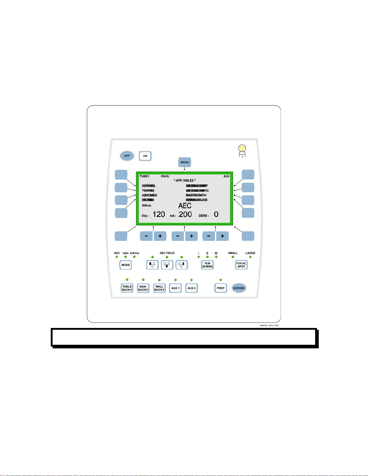
The control console allows the operator to select the technique factors, image receptors, etc.,
and to initiate an X-ray exposure.
1.1.2 Features
The following are the main features of and the options available for the generator:
•Integral low speed starter, compatible with X-ray tubes with type “R” stator. Optional compatibility with
GE 23/23 Ωequal impedance “E” stator.
•Optional dual-speed starter on some models of MAGNUM C®DR (not available on 208 / 230 VAC,
1-phase & 3-phase units), compatible with tube types listed in chapter 2.
•Capable of interfacing with various DR imaging systems (MAGNUM C®DR only).
•24 VDC, 110, or 220 VAC power source for Buckys (fused at 0.8 amps).
•24 VAC 150 watts power source for collimator lamp.
•24 VDC 45 watts power source for system locks.
•Optional AEC.
•Optional DAP (Dose-Area Product).
•Tomography