Aperia Technologies Halo Connect User manual

USER MANUAL
Keep this manual in the vehicle for future reference.
Read this manual before using this product. Failure to follow the
instructions and safety precautions in this manual may result in
serious injury or death.
IN-100CM


SAFETY WORDS AND SYMBOLS
Please pay attention to special symbols used through this manual
to convey important information. Hazard signal words such
as WARNING, CAUTION, or NOTICE are used throughout this
manual. Information accented by these words indicates a point of
emphasis and importance. The following denitions comply with
ANSI Z535.6 and indicate the use of signal words as they appear
within this manual.
This is the safety alert symbol. It is used to
alert you of potential physical injury hazards.
Obey all safety messages that follow this
symbol to avoid possible injury or death.
WARNING indicates a hazardous situation
that, if not avoided, could result in serious
injury or death.
CAUTION indicates a hazardous situation
that, if not avoided, could result in minor or
moderate injuries.
NOTICE is used to address practices which
could result in damage to equipment or
property.
IMPORTANT SAFETY INFORMATION
The Halo Connect Gateway and its components should be
installed and maintained in accordance with the instructions in
this manual. Proper installation of the Halo Connect is critical to
ensure safe use of the device. Failure to do so may result in injury
or death, damage to equipment, material or property. Carefully
read, understand and follow all safety related information within
this manual.
Exercise caution when working with the vehicle
power sources to avoid injury.
3

Contents
Safety
3 Important Safety Information
3 Safety Words and Symbols
Introduction
5 Halo Connect Web Services
5 Halo Connect Gateway
5 Halo Connect Mobile Application
Getting Started
6 System Components
Halo Connect Installation
7 Step 1: Afx gateway ID sticker to vehicle
8 Step 2: Determine where to put the Gateway
9 Step 3: Locate power source and ground
10 Step 4: Attach TPMS antenna to vehicle
10 Step 5: Attach GPS antenna to vehicle
11 Step 6: Connect cables to Gateway
11 Step 7: Attach Gateway to vehicle
11 Step 8: Conrm Gateway power
12 Step 9: Install TPMS sensors
12 Step 10: Download mobile app
13 Step 11: Congure mobile app
13 Installation Checklist
13 Technical Specications
14 Regulatory
Customer Support
Phone 1-844-RUN-HALO
Website www.aperiatech.com
Sales [email protected]
4

Introduction
Halo Connect Web Services
Web Services give you full control over your data, alerts, and
reports. All of the issues in the eet, active and historical, are
easily viewed and organized, using the systems that eets are
most comfortable with, such as email. For each vehicle issue,
the portal gives recommended actions for resolution. For an
understanding of the bigger picture, we distill the data into
analytical reports to visualize the trends in the eet.
Access the web portal at: https://haloconnect.aperiatech.com
Halo Connect Gateway
The Halo Connect Gateway is a tire pressure monitoring
device comprised of a durable enclosure that is secured in the
cab of the vehicle. It uses a built-in LTE cellular connection to
send data to the cloud and a Bluetooth connection to talk to
mobile devices. It also has GPS, which noties the location in
which a vehicle issue transpired.
Halo Connect mobile application
The Android mobile application makes installation and
conguration of the Gateway and sensors seamless, requiring
just two data matrix scans per install. The app allows you to
choose between various truck congurations, register the
vehicle in our system, and add or replace sensors. Please note
that iOS is not currently supported.
Access the app at: https://www.aperiatech.com/HC-app
5

Getting started
INSTALLATION TOOLS (not included)
10. 5/16" Hex Head Socket
11. Tool necessary to access fuse panel
12. Wire Crimper
13. Cutters (for cutting cable ties)
14. Isopropyl Alcohol and Wipes
15. Multimeter
16. Mobile device running Android 6.0 or higher
SYSTEM COMPONENTS
1. Pack of Halo Connect sensors
2. Power cable with mini fuse connector
3. Sensor antenna
4. TPMS cable
5. Cellular antenna
6. GPS antenna
MOUNTING PARTS
7. #10 x 5/8" screws (5/16" hex head)
8. UV Stabilized 8" cable ties
9. 1" x 1" Velcro®squares
HALO Connect Gateway
6

HALO CONNECT INSTALLATION
Step 1. AFFIX GATEWAY ID STICKER TO VEHICLE
The gateway ID sticker is located on the bottom of the
gateway. It contains information necessary for pairing and
troubleshooting the gateway.
Before afxing the gateway ID sticker, make sure the vehicle
conguration on the product box matches that of the vehicle.
Select an easy to access location to permanently attach the
gateway ID sticker inside the vehicle. Aperia recommends the
door jamb.
Clean the surface of the placement area to ensure that the
sticker does not come off. Firmly place the sticker in the
placement area.
7

8
BEST GATEWAY LOCATION
Inside cab of vehicle.
Wall-mounted behind seat.
Minimum distance of
8 in (20 cm) away from driver
and passengers.
HALO CONNECT INSTALLATION, CONT'D
Step 2. Determine where to put Gateway
Select a location to permanently attach the gateway inside the
cab of the vehicle.
Consider that the gateway will have power and antenna cables
attached to it that need to be routed to locations specied in
later steps. See Installation, Step 7 for further instructions on
attaching the gateway to the vehicle.
Other gateway placement considerations include:
• Should be accessible for maintenance.
• Should be wall-mounted, at least 8 in (20 cm) away from
driver and passengers.
• LTE cellular antenna should not be obscured.
• Does not interfere with passenger access or storage.
• Protected from spills and passenger movement in vehicle.
• Does not interfere with seatbelt.
• Allows for permanent attachment using self tapping screws
or other secure attachment based on eet preference.
Before attaching the gateway to the vehicle,
review the entire install procedure, and ensure the antenna
and power cables are safely routed to the recommended
locations.

9
HALO CONNECT INSTALLATION, CONT'D
Step 3. Locate power source and ground
In order for the vehicle's tires to be monitored 24 hours,
the Gateway power cable must be connected to a 24 hour
continuous or unswitched 12 or 24V power source and be
securely grounded to the vehicle chassis.
A mini add-a-fuse connector is included with the Gateway. If
using this add-a-fuse, locate the vehicle's fuse box and select
the power and ground locations.
If you are using a different power connection be sure to add a
fuse to the positive power cable.
If the gateway is connected to an alternator circuit, or if it is de-
powered for any reason (such as activating a kill switch), the
gateway will not operate, and it will lose data. Ensure that the
gateway is connected to a battery circuit.
The positive wire of the power cable must be
fused. An un-fused power cable may over-heat and lead to a
vehicle re.
Use a multimeter to test the power source and ground
with the ignition on and off to ensure that the voltage of the
chosen fuse slot is correct and continuous.
1
Fuse Rating: 1 Amp

10
HALO CONNECT INSTALLATION, cont'd
Step 4. Attach sensor antenna to vehicle
The sensor antenna must be placed outside on the rear of
the vehicle, and the cable needs to be routed back to the
Gateway. Find or make an opening in the cab to route the
cable from the Gateway to the outside of the vehicle.
Once the cable is routed, nd or make a .5 in (1.5 cm) hole
through a metal portion of the truck. Guide the end of the
TPMS cable through the hole, and screw the antenna to the
hole and cable, using the attached nut.
Step 5. Attach GPS antenna to vehicle
The GPS antenna must be placed outside on the rear of
the vehicle, and the cable needs to be routed back to the
Gateway. Find or make an opening in the cab to route the
cable from the Gateway to the outside of the vehicle. Remove
adhesive protector from the antenna, stick the Velcro® square
on the dashboard inside the cab, and afx the antenna to the
square.
Avoid creating a tripping hazard when routing
the TPMS cable on the exterior of the vehicle.
Expected vehicle operation must be considered
when routing the sensor antenna to avoid damage to the
antenna. Make sure the antenna is routed so it won't be
excessively stretched or cut when the vehicle turns or when
the suspension is compressed. Protect the antenna from heat
sources, such as exhaust, when routing.
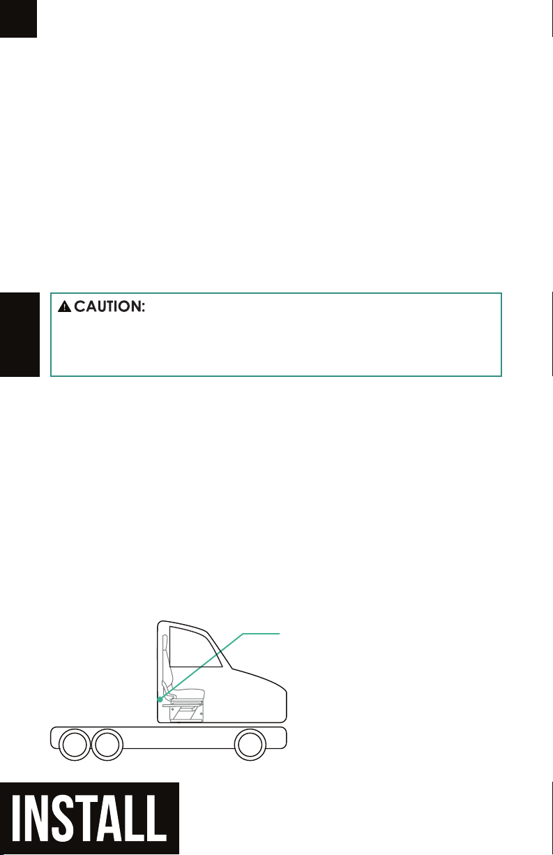
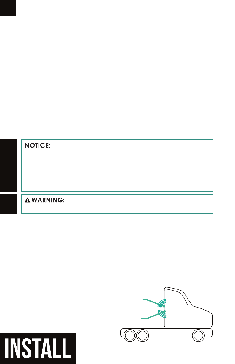
BEST GPS LOCATION
On rear of exterior of vehicle
BEST TPMS ANTENNA LOCATION
On rear of exterior of vehicle,

HALO CONNECT INSTALLATION, cont'd
Step 7. Attach Gateway to vehicle
Use the included mounting screws and a 5/16" socket to
securely attach the Gateway in the location selected in Step 1.
ON/OFF
ANTENNAS
4x
Step 6. Connect cables to gateway
On the gateway, the side label marks the port for each of the
cables, as seen below:
Step 8. Confirm gateway power
On the Gateway, ensure that the power LED is emitting green.
Ensure the cables are securely attached to the
Gateway to avoid loosening due to vibration during vehicle
operation.
Ready Error Power
11

HALO CONNECT INSTALLATION, cont'd
Step 9. Install Halo Connect Sensors
Locate the sensor pack. Each sensor has a label that species
which valve stem the sensor must be screwed onto.
Screw each sensor onto the correct valve stem by hand, rather
than using a tool that could potentially break the sensor. Some
product kits contain sensors for Halos. Sensors for Halos
should be attached to the Halo hose.
A contaminated, corroded, or damaged valve
stem or sensor seal may cause a poor seal between the
sensor and valve stem resulting in a tire leak.
Step 10. Download mobile app
On the Gateway, ensure that the Ready LED is emitting blue.
You must download the Halo Connect app from the Google
Play Store onto a mobile or tablet device running Android 6.0
or later to complete the pairing process.
App Link: http://aperiatech.com/HC-app
How to Read Tire Position Label
This sensor should be installed on:
R = Right side of vehicle (from driver perspective)
2 = 2nd Axle (steer tire is axle 1)
Inner = Inner tire position
R2 INNER
12

Step 11. Configure MObile App
In order to congure the gateway, you will need the following
information:
• Fleet ID - get this unique code from the primary Aperia
account holder at your company or shop, typically a eet
manager or shop manager
• Fleet Vehicle ID - truck number typically found on either
door
• VIN - 17-character vehicle identier typically found on the
driver-side door jamb
Installation Checklist
❒Gateway is securely mounted to the wall of the cab.
❒Gateway LEDs are emitting green and blue.
❒All antennas and cables are tightly connected to the
gateway.
❒LTE antenna is not covered or obstructed.
❒GPS and TPMS antennas are tightly secured to the cab.
❒Cables are neat, not loose.
❒Crimps on the power cable are secure.
❒Power cable is connected to continuous power.
❒Power cable is securely grounded.
Technical Specifications
Operating Voltage 9-28V DC
Operating Current 100-200 mA
Operating Temperature -40º - 158º F (-40º - 70º C)
Storage Temperature -40º - 185º F (-40º - 85º C)
13

14
Regulatory
RF Exposure
This equipment complies with FCC and IC radiation exposure limits set forth for an uncontrolled
environment. This equipment should be installed and operated with minimum distance of 20 cm
between the radiator and your body. This transmitter must not be co-located or operating in conjunction
with any other antenna or transmitter.
Cet équipement est conforme aux limites d'exposition aux radiations de la FCC et de l'IC dénies pour
un environnement non contrôlé. Cet équipement doit être installé et utilisé à une distance minimale
de 20 cm entre le radiateur et votre corps. Cet émetteur ne doit pas être co-localisé ou fonctionner en
conjonction avec une autre antenne ou un autre émetteur.
This device complies with part 15 of the FCC rules and RSS-247 of Industry Canada. Operation is
subject to the following two conditions: (1) this device may not cause harmful interference, and (2)
this device must accept any interference received, including interference that may cause undesired
operation.
Le présent appareil est conforme aux CNR d'Industrie Canada applicables aux appareils radio
exempts de licence. L'exploitation est autorisée aux deux conditions suivantes : (1) l'appareil ne doit
pas produire de brouillage, et (2) l'utilisateur de l'appareil doit accepter tout brouillage radioélectrique
subi, même si le brouillage est susceptible d'en compromettre le fonctionnement.
This Class B digital apparatus complies with Canadian ICES-003.
Cet appareil numérique de la classe B est conforme à la norme NMB-003 du Canada.
NOTE: The manufacturer is not responsible for any radio or TV interference caused by unauthorized
modications to this equipment. Such modications could void the user’s authority to operate the
equipment.
NOTE: This equipment has been tested and found to comply with the limits for a Class B digital device,
pursuant to part 15 of the FCC Rules. These limits are designed to provide reasonable protection
against harmful interference in a residential installation. This equipment generates uses and can
radiate radio frequency energy and, if not installed and used in accordance with the instructions, may
cause harmful interference to radio communications. However, there is no guarantee that interference
will not occur in a particular installation. If this equipment does cause harmful interference to radio
or television reception, which can be determined by turning the equipment off and on, the user is
encouraged to try to correct the interference by one or more of the following measures:
- Reorient or relocate the receiving antenna.
- Increase the separation between the equipment and receiver.
-Connect the equipment into an outlet on a circuit different from that to which the receiver is connected.
-Consult the dealer or an experienced radio/TV technician for help
- This device and its antenna(s) must not be co-located or operating in conjunction with any other
antenna or transmitter.
“This radio transmitter 24637-HALOC has been approved by Innovation, Science and Economic
Development Canada to operate with the antenna types listed below, with the maximum permissible
gain indicated. Antenna types not included in this list that have a gain greater than the maximum gain
indicated for any type listed are strictly prohibited for use with this device.”
Cet émetteur radio 24637-HALOC a été approuvé par Innovation, Sciences et Développement
économique Canada pour fonctionner avec les types d'antenne énumérés ci-dessous, avec le gain
maximal autorisé indiqué. Les types d'antenne non inclus dans cette liste et dont le gain est supérieur
au gain maximal indiqué pour l'un des types répertoriés ne sont strictement pas autorisés pour une
utilisation avec cet appareil.
Antenna Type Max. Gain
LTE Whip 3.0 dBi
ZigBee PCB 1.0 dBi
Bluetooth (BLE) PCB -1.61 dBi

Responsible party details
Company name: Aperia Technologies
Address: 1616 Rollins Road, Burlingame, CA 94010
Contact Person: Robert Lawson
Email: [email protected]
Phone No.: 16507413231
Fax No.: 4152734649
Product details
Product: Halo Connect Gateway
Brand name: Aperia Technologies
Model name: GW-10, GW-20
Manufacturer: Volansys Technologies Pvt Ltd.
Address: A-503, Mondeal Square, Near Crown Plaza Hotel, S. G
Highway, Ahmedabad 380 015, Gujarat.
We hereby declare that the equipment bearing the trade name and model
number specied above was tested conrming to the applicable FCC Rules
under the most accurate measurement standards possible, and that all the
necessary steps have been taken and are in force to assure that production
units of the same equipment will continue to comply with the Commission's
requirements.
Applied Standards Report No.:
United states CFR 47 Part 15 Subpart B -
Electromagnetic Emissions (Unintentional Radiators) BL-HK18C0003-401
The product complies with Part 15 of the FCC Rules. Operation is subject to the
following two conditions: (1) this device may not cause harmful interference, and
(2) this device must accept any interference received, including interference that
may cause undesired operation.
Supplier's Declaration of Conformity
Changing the world one revolution at a time
Signature:
Print name: Robert Lawson
Date of issue: 3/20/2019

Aperia Technologies, Inc.
1616 Rollins Rd.
Burlingame, CA 91040
Phone: (650) 741-3231
Fax: (415) 524-2449
www.aperiatech.com
© 2019 Aperia Technologies, Inc.
IN-100CM
91-00006672
PMN: Halo Connect Gateway
Model No.: GW-10 (for xBR type sub-1GHz Rx)
Model No.: GW-20 (for cc1310 type sub-1GHz Rx)
Printed in United States of America
IN-100CM
QTY:
Part Number:
1
Description:
User Manual, Halo Connect
Other manuals for Halo Connect
1
Table of contents
Other Aperia Technologies Power Tools manuals