Apogee DRACO BG User manual

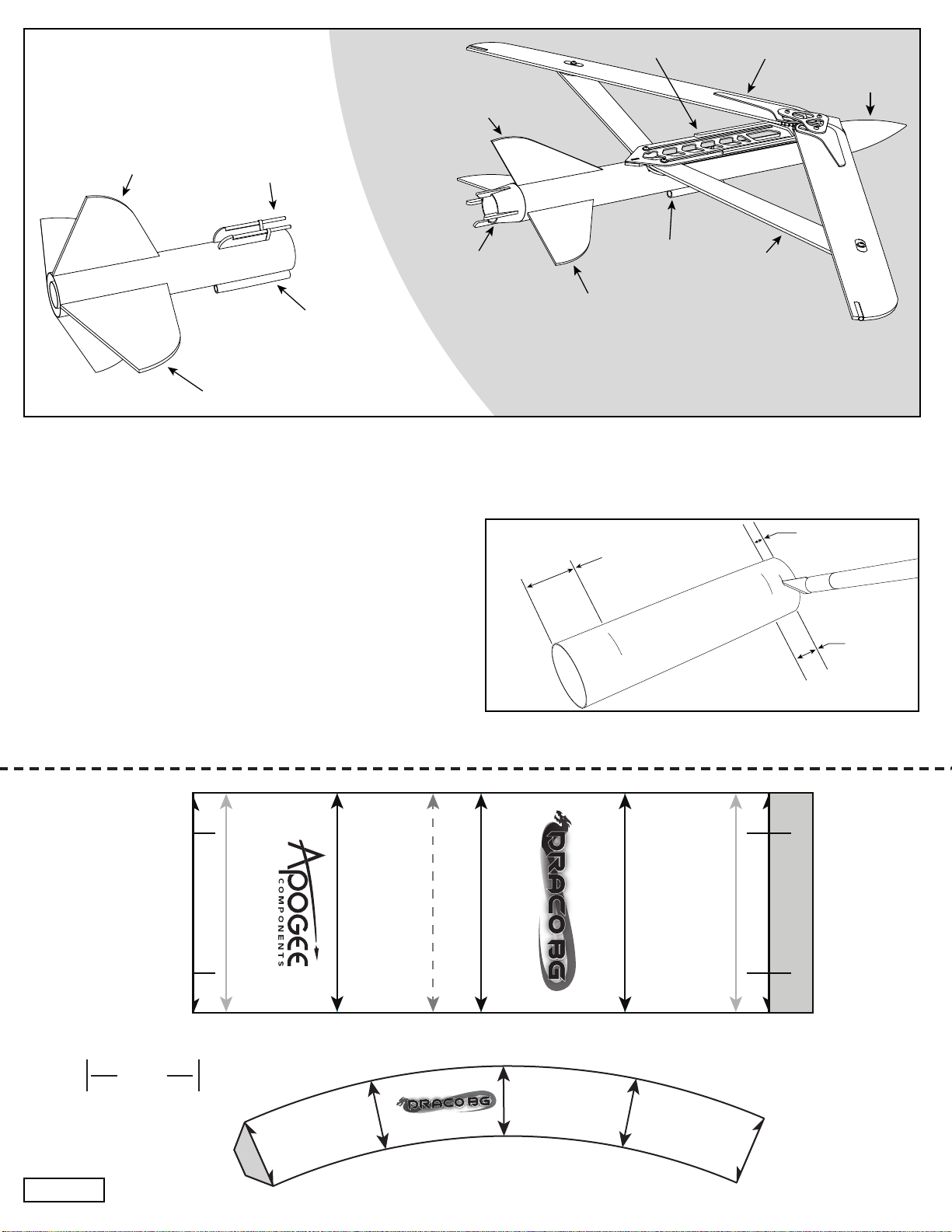
The Draco BG is a model boost glider (BG) based on the
real-life Boeing GBU-39 SDB (Small Diameter Bomb) which
originally was an air-drop ordinance and was later modied
for launching from ground vehicles. This modied version is
known as the GLSDB (Ground-Launched Small Diameter
Bomb) and is a precision weapon system that allows delivering
a payload of 93kg (205 lbs) to a location within a range of 150
km (93 mi) from the mobile launch platform. Development of
the GLSDB was a joint project of Boeing and the Saab Group.
The Draco BG copies the overall conguration of the GLSDB
and the unique folding wing arrangement.
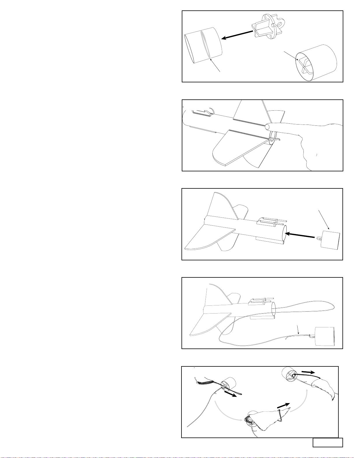
Despite the fancy wing mechanism, ights of the Draco
BG model are simple. It launches upward on 24mm diam-
eter rocket motors. The simple interstage/wing-lock system
ensures reliable transition of the upper stage to glide congu-
ration while the booster recovers under a parachute. While a
challenging build, the Draco BG is a fantastic rocket for those
interested in mechanical design, gliders, and military history.
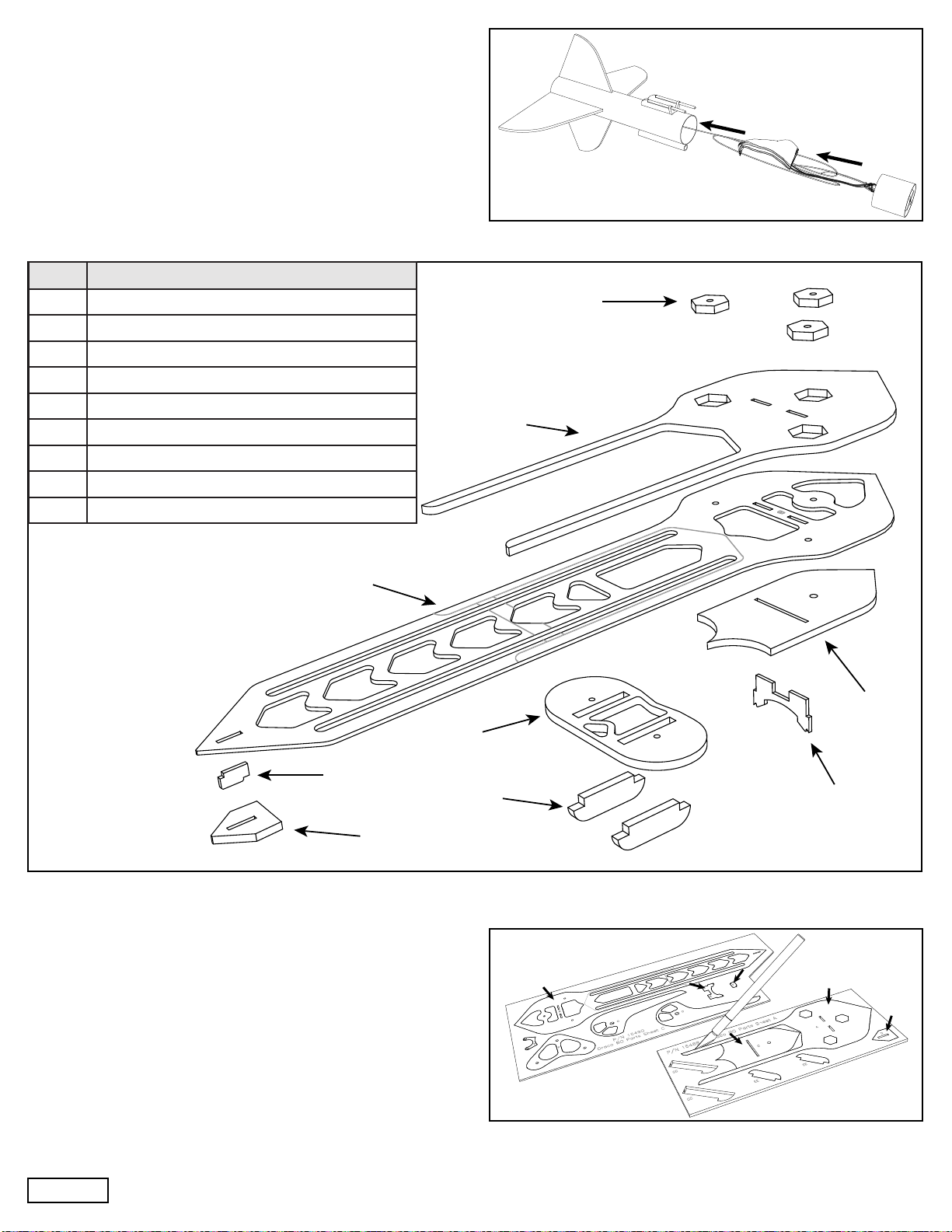
Item # Item Name Qty
10091 AT-24/3.75” (Motor Tube) 1
10151 AT-41.6/9” (Booster Tube) 1
10154 AT-41.6/18” LC (Fuselage Tube) 1
12976 #4 Flat Washer 4
12977 #4 3/16”x1/4” Unthreaded Off-White Nylon
Standoff 5
12978 #4 3/16”x5/32” Unthreaded Off-White Nylon
Standoff 2
12979 4-40 x 1/2 Black Nylon Panhead Screw 7
13031 CR-18/24 1
13035 CR-24/29 1
13123 AC-41.6/1.5” LC 1
13051 1/8" Launch Lug 1" Long 2
13056 1/4" Launch Lug 3" Long 2
14263 1/8" x 2.5" Wood Dowel 2
15015 CR-24/41.6 Cardstock (Rectangle) 1
15487 Draco BG Jig Sheet Cardstock 1
15488 Draco BG Parts Sheet A 1/8”x4” Balsa 1
15489 Draco BG Parts Sheet B 1/8” Ply 1
15490 Draco BG Parts Sheet C 1/16” Ply 1
15731 Draco BG Wing Sheet 1/8”x4” Balsa 2
15732 Draco BG Fin Sheet 1/8”x4” Balsa 1
15733 Draco BG Stabilizer Sheet 3/32”x4” Balsa 1
19469 PNC-41mm (BT-60) 1
24003 #117B Rubber Band 1
24044 Crimped "E-size" Engine Hook 1
29090 12" Printed Nylon Parachute 1
29518 100# Kevlar x 5 feet 1
29600 Clay Nose Wt 5g 1
31271 Instructions Sheet A 1
31272 Instructions Sheet B 1
31273 Instructions Sheet C 1
31274 Instructions Sheet D 1
31275 Instructions Sheet E 1
31276 Instructions Sheet F 1
39059 Face Card 1
41116 Decal Sheet 1
Skill Level 5
Extremely Challenging
Draco BG Parts List
Optional Tools / Finishing Supplies
Fin Alignment Guide (P/N 35546)
Flat Needle File
Wood Filler
Sanding Sealer
Extra Fine Sandpaper (600 grit)
Spray Paint
Wood Dowel
Ruler or Calipers
Needed Tools and Materials
Hobby Knife with Sharp Blades
Scissors
Razor Saw
Wood Glue
Thin CyAAdhesive
Medium CyAAdhesive
Masking Tape
Medium and Fine Sandpaper (180, 320 grit)
Aluminum Angle
4-40 Tap Page 1
Assembled In USAKit #05065
Skill Level 5
Manufactured in the USA by:
Apogee Components Inc.
Colorado Springs, Colorado, USA
www.ApogeeRockets.com
Instruction Sheet A: P/N 31271 *Updated 9/1/2023

Assembly Booster Steps
1. Mark the motor mount tube (AT-24/3.75”) with a pencil
1/2” (13 mm) from either end. Cut a 1/8” (3mm) wide slot,
1/4”(6 mm) from the front of the motor mount tube.
Step 1
Fin - X
Fin - Y
Fin - Y
Booster Fin
Marking Guide
Overlap
Wing Lock
Wing Lock
Launch Lug
Fin - X
Forward
Edge
Forward
Edge
Boattail
Marking Guide
Vane
Vane
Vane
Vane
This image outlines the basic nomenclature used in this instruction booklet for major parts of the Draco BG.
Additional exploded views of the more complicated assemblies are included later.
Horizontal Booster Fin
Launch Lug
Wing Lock
Vertical Booster Fin
Boattail
Horizontal Stabilizer
Vertical Stabilizer
Launch Lug Stay Wing
Wing Frame Main Wing Nose Cone
1/2” (13mm)
1/2”
(13mm)
1/4” (6mm)
1 inch
Page 2

2. Using a sharp hobby knife, remove the two CR-24/41.6
centering rings from the small cardstock sheet (P/N
15015).
3. Install the motor hook by sliding it into the cut slot in the
tube with the hook end hanging over the aft end of the
tube. Wood glue one cardstock centering ring into place at
the line 1/2” (13 mm) from the aft end of the motor mount
tube.
4. Tie the shock cord around the middle of the motor mount
tube.
5. Route the shock cord through the other cardstock center-
ing ring then wood glue the centering ring into place at the
line 1/2” (13 mm) from the front of the motor mount tube.
Pull the shock cord tight against the backside of the cen-
tering ring and apply a wood glue llet to ensure the shock
cord stays in place.
6. Route the shock cord through the larger green centering
ring (CR-24/29) and using wood glue, secure the ring into
place at the front of the motor mount tube ush against the
forward centering ring.
Step 4
Step 5
Step 6
Step 2
Step 3
1/2”
(13mm)
1/2” (13mm)
Mount rotated
Page 3
Instruction Sheet B: P/N 31272

7. Put a ring of wood glue inside the front lip of the motor
tube. Seat the smaller green centering ring (CR-18/24) in
the front of the motor mount tube with wood glue. Install
the ring so that it sits against the engine hook so that it
acts as an engine block.
8. Using scissors, cut out the n marking guide and tape it
around the 9” long, 41.6mm diameter (BT-60) tube. Copy
marks for all of the lines onto the tube with a pencil. It is
also useful to label the different lines and the forward end
of the tube to coincide with the forward label on the mark-
ing guide. This is the booster tube.
9. Extend the lines along the length of the tube using an
aluminum angle to ensure the lines are straight along the
tube. The n lines can be drawn about halfway from the aft
end of the tube and the support lines and launch lug line
can be drawn about halfway from the forward end of the
tube.
10. Measure 3/4” (19mm) from the front of the tube, and using
a pencil, mark the location on the upper support lines.
11. Route the shock cord back through the center of the motor
tube and glue the motor mount assembly into the booster
tube. Using a dowel, apply wood glue at points 1/2” (13
mm) and 3” (76 mm) deep inside the tube, then slide the
motor mount assembly into the tube so that the aft end of
the motor mount tube is ush with the aft end of the boost-
er tube. Set aside to dry.
Step 9
Step 10
Step 11
Step 7
Fin - Y
Fin - X
Wing Lock
Wing Lock
Step 8
Forward
3/4” (19mm)
1/2” (13mm)
3” (76mm)
Forward
Forward
Forward
Page 4

12. Before removing the booster ns from the 1/8” balsa sheet
(P/N 15732), sand the surface smooth on both sides using
a ne grit sandpaper (320 grit).
13. Remove the booster ns from the sheet using a hobby
knife and sand the edges of the parts to remove any rem-
nants of tabs.
14. Remove the two wing lock supports (CC) from the 1/8”
balsa sheet (P/N 15488) using a sharp hobby knife and
sand off the remnants of any tabs using ne grit sandpaper
(320 grit).
15. Using ne sandpaper (320 grit) smooth and bevel one
end of one of the 2-1/2” long (63 mm) hardwood dowels.
Glue the other (at) end of the dowel into the notch in one
of the wing lock supports (CC), tape it in place and let the
assembly dry. Repeat the sanding and assembly for the
second dowel and support. Optional: sand one of the
dowels 1/8” (3mm) shorter than the other so that the
wing locks can be aligned separately, making ight
preparation easier.
16. Using wood glue, glue the ns onto the booster tube with
the ns aligned on the lines marked on the tube. The
larger ns provide stability in the plane of the glider wings
and should be attached to the Fin-Y lines on the tube.
The shorter ns are attached on the Fin-X lines and fall
between the wing lock lines on the top. A n alignment jig
can be helpful to ensure accurate construction but the ns
are too tall for most jigs to completely enclose the ns and,
therefore, only the front sections of the ns will be retained.
Take care to align the ns accurately along the long axis of
the tube to ensure the straightest boost. Allow the ns to
dry before continuing.
Step 14
Step 15
Step 16
Step 12
Step 13
Bevel Ends
Yes
No
Page 5
Instruction Sheet C: P/N 31273

17. Remove the wing lock support frame (T) from the 1/16”
plywood sheet (P/N 15490). Using a small drop of wood
glue at the front of each balsa support, slide the two wing
lock assemblies as far as they will go into part T. Then glue
the whole wing lock assembly onto the booster tube with
the support frame 3/4” (19 mm) from the forward end of the
tube. The alignment lines drawn on the tube are placed at
the outside edges of the wing lock supports. Take care that
the supports and pins are aligned with the long axis of the
tube to ensure reliable separation and wing extension.
18. Wood glue one 1/4” x 3” long launch lug into place cen-
tered on the marked line and ush with the front edge of
the booster tube.
19. Using a sharp hobby knife, remove the two piston frames
(Q and R) and the piston ring (S) from the 1/8” plywood
sheet (P/N 15489).
20. Apply wood glue to the notches of the two piston frames
(Q and R) and slide them together.
21. Apply wood glue as shown on the front edges of the as-
sembled piston frame and slide the piston ring into place.
Add wood glue llets along the joints between the piston
frames and piston ring for strength.
Step 19
Step 20
Step 21
Step 17
Step 18
3/4” (19mm)
Fillet all joints
Wing lock support frame
Page 6

22. Apply a bead of wood glue to the inside of the short red
coupler tube at roughly the middle and slide the piston
frame and ring assembly into the tube. To correctly align
the frame and ring in the tube, place the tube and the at
end of the frame against the table so that they are ush.
Ensure that the edges of the piston ring have llets where
they touch the coupler tube but leave the slots clear so
that the glider is able to slide into place later.
23. Apply wood glue llets to the joints at the base of the ns,
the launch lug, and the supports by applying a bead of
wood glue and shaping the llet with the tip of a nger.
24. Once the booster has dried, test t the piston in the tube
witht the loop side facing aft, and adjust so that it ts snug-
ly with little or no wobble but does not require excessive
force to move. If the piston is tight enough that it becomes
difcult to move, sand its surface with a ne sandpaper
(320 grit) until it moves more easily.
25. Pass the shock cord back through the motor tube then tie
it onto the loop in the piston. Apply tape to the tail of the
shock cord to prevent the knot from coming undone.
26. Attach the parachute by collecting the center of the para-
chute’s shroud lines. Then pass them through the loop on
the piston, and pull the parachute back through the ends,
pulling the knot tight.
Step 24
Step 25
Step 26
Step 22
Step 23
Apply glue inside
tube
Frame ush
with tube
Sand for
sliding t
Tape
Page 7
Instruction Sheet D: P/N 31274

27. The physical build of the booster is now complete and the
parachute and piston can be installed in the end of the
tube to await nishing.
Glider Assembly Steps
Wing Frame:
28. Using a sharp hobby knife, remove the main wing frame
(B) and the two wing frame alignment guides (E and F)
from the 1/16” plywood sheet (P/N 15490) as well as the
upper wing frame (A) and the forward and aft wing frame
spacers (C and D) from the 1/8” balsa sheet (P/N 15488).
Remove and discard the many small cutouts from with-
in the main wing frame (B), the hexagonal pieces in the
upper wing frame (A) and sand down any prominent tab
remnants on all the parts using ne sandpaper (320 grit).
Step 27
Step 28
3x J
A
B
F
D
V
2x EE E
C
Label Part
A Upper Wing Frame
B Main Wing Frame
C Forward Wing Frame Spacer
D Aft Wing Frame Spacer
EForward Wing Frame Alignment Guide
F Aft Wing Frame Alignment Guide
J Hex Insert
VStay Tie Frame
EE Stay Tie Guide
Page 8

29. Apply a small amount of medium CyA adhesive to the slot
in the forward spacer C and install the tabs of the align-
ment guide E (opposite the curved side) such that the tabs
poke through the frame C and the curved portion is ush
with the surface of the balsa in the center. Check that the
frame is square to part C and allow the adhesive to hard-
en.
30. Dry t the assembly onto the main frame B on the side
opposite the engraving on the surface of B and using a
pencil, trace around the forward spacer C.
31. Apply medium CyA adhesive to the main frame B within
the pencil outline then install the assembled spacer C and
frame E onto the main frame B. Allow the tabs on E to
align the large parts and check that the points on the balsa
part C and the plywood part B are touching to ensure cor-
rect alignment.
32. Apply medium CyA adhesive uniformly to the upper (en-
graved) side of main frame B in the area covered by the
upper frame A (outline marked by engraving). Glue the up-
per frame A into place, taking care to align the two frames
along the outside edge.
33. Aligning the engraved dot on part F at the forward end of
the slot, place the alignment tab F on the bottom of the
main frame B, opposite the engraving and the upper frame
A that was just installed. Apply a couple of drops of thin
CyA adhesive to tack part F in place during the next step.
Step 29
Step 30
Step 31
Step 32
Step 33
Flush
Engraved side down
Engraved side up Edges align
Engraved side of
frame down
Engraved dot
Page 9
Instruction Sheet E: P/N 31275

34. Apply medium CyA adhesive to the slot and one surface of
the aft spacer (D) then slide it over the alignment tab (F).
35. Using a sharp hobby knife remove three of the bolt hex
inserts (J) from the 1/8” plywood sheet, parts sheet B (P/N
15489).
36. Insert the plywood inserts (J) into the three pockets on the
upper side of the wing frame and secure them by running
a bead of thin CyA adhesive along the edge. Apply enough
adhesive that it will soak down into the joint and securely
hold the inserts in place.
37. Remove the stay tie frame (V) from the 1/8” plywood sheet
(P/N 15489) and the two stay tie guides (EE) from the 1/8”
balsa sheet (P/N 15488), then insert the balsa guides (EE)
into the plywood stay tie frame and secure by running a
bead of thin CyA adhesive along the joint. This assembly is
the stay tie and it holds the small (stay) wings together as
the wings fold and extend.
38. Once the glue has dried on the wing frame assembly and
stay tie assembly, use a ne (320 grit) sandpaper to sand
all of the edges – including inside the long slots – so that
they are slightly rounded and smooth. Removing imper-
fections and sharp edges reduces the likelihood that the
mechanism will catch during operation and increase the re-
liability of wing extension. Once sanded, set the frame and
stay tie aside for later assembly of the wing mechanism.
Step 34
Step 35
Step 36
Step 37
Step 38
Smooth the edges
D
J
J
JJ
“A” side up
EE
Page 10

Wings:
39. Remove the root pivots (H1 & H2) from the 1/8” plywood
sheet (P/N 15489) and the main wings (G) from the two
1/8” balsa wing sheets (P/N 15731). Sand the at edges of
the root pivots with medium sandpaper (180 grit) to rough-
en up the laser cut surface and improve glue adhesion.
40. Apply wood glue to the inside edges of the root pivots and
put them into place on the wing pieces, then use masking
tape on the bottom side (opposite the engraving) to hold
the plywood piece in place as the glue dries. Ensure that
the pivots are at and that there is as little gap as possible
between the plywood and balsa parts. Repeat for the sec-
ond wing and root pivot, then check that the wings form a
left/right pair when the tape side of the joint is down on the
table before allowing the joints to dry.
Step 39
Step 40
O
G
K
N
M
J
H1/H2
L
Label Part
G Main Wing
H1/H2 Root Pivot
J Hex Insert
KStay Tip Pivot
L Stay Wing
MStay Tip Spacer
N Stay Wing Stiffner/Pivot
O Main Wing Stiffner
Roughen
Edges
Tape
Step 40 Leading edge
Engraved labels face up
GG
H1
H2
Page 11
Instruction Sheet F: P/N 31276

Step 45b
Step 44
Step 45a
41. Remove the two stay tip pivots (K) from the 1/8” plywood
sheet (P/N 15489) and press them into place on both
main wings. Secure them in place by wicking thin CyA
adhesive around the edges of K.
42. Glue the 1/8” launch lug tubes into the slots at the tips of
the wings using wood glue. Then place some masking
tape along the bottom surface to hold the wing and tube in
place while the glue dries.
43. Insert one of the shorter (5/32”, 4mm) nylon standoffs in
the root pivot hole. It will be used it to align the wing root
stiffener. The standoff will sit below the surface of the
stiffener but will stick up enough to assist with alignment.
Remove the two wing root stiffeners (O) from the 1/16”
plywood sheet (P/N 15490) and apply a thin layer of wood
glue to the label side of the stiffener then mount it onto the
wing, using the nylon standoff to center it.Align the long
straight edge of the stiffener so that it is lined up parallel
with the leading edge of the wing. Then apply pressure to
the stiffener joint to prevent the thin plywood from curling
up as it dries. This can be achieved by placing a sheet of
glass or wax paper over the wing and weighing it down
with a book. Repeat for the second wing and allow them to
dry under pressure.
44. Remove the two stay wing stiffener/pivots (N) from the 1/8”
plywood sheet (P/N 15489) and the two stay wings (L) and
two stay tip spacers (M) from the 1/8” balsa wing sheets
(P/N 15731).
45. Apply wood glue to the exterior edge of the stay wing stiff-
ener/pivot (N) then install into the slot on the stay wings.
Clean up any glue that squeezed out and apply tape
to one side of the wing to hold it together as it dries. As
before, apply the tape to the bottom surface (engraving on
part N facing up). Repeat for the second piece. The stay
wings will form a left/right pair where the pivot holes are
toward the center and the stiffeners are toward the forward
half of the wings.
Step 41
Step 42
Step 43
Compress while
glue dries
Left
Right
K
Edges are parallel
Page 12

Step 49
Step 50
46. Apply a thin layer of wood glue to the tip spacers (M) and
attach to the outer tips of each stay wing ush with the
outer radius. For maximum strength, rotate the spacers so
that the grain in the spacers is at a 90 degree angle to the
grain in the stay wings. Apply pressure as the glue dries in
a similar way to attaching the main wing stiffeners previ-
ously to ensure that the parts remain at and do not curl
away from each other as a result of the water in the wood
glue.
47. Using a sharp hobby knife remove the remaining two hex
inserts (J) from the 1/8” plywood sheet (P/N 15489) and
press into the ends of the stay wings. Secure the inserts
in place by running a bead of thin CyA adhesive along the
joint.
48. Using a sharp hobby knife, remove the vertical (Z) and hor-
izontal stabilizers (AA) from the 3/32” thick stabilizer sheet
(P/N 15733). Using ne sandpaper (320 grit), sand any
remnants of the retaining tabs off of the outer edges of the
parts. The alignment tabs themselves need not be sanded
as they will end up inside the fuselage.
49. The vertical stabilizer (Z) has a symmetrical airfoil, that is,
it should be as close to the same on both sides as pos-
sible. Round the leading edge (the front) of the stabilizer
using medium sandpaper (180 grit) then taper the trailing
edge (the back) down to a thickness of around 1/32” (0.75
mm). Thinner trailing edges are aerodynamically more
efcient but are more prone to damage. Once the vertical
stabilizer has been airfoiled, smooth the surface with ne
sandpaper (320 grit).
50. The horizontal stabilizers are shaped with a curve on only
one side (the bottom) while the other side (the top) is at.
Lay out the two horizontal stabilizer pieces in a pair to
keep track of which side to sand, then round the leading
edge of each horizontal stabilizer (AA) using medium
sandpaper (180 grit). Taper the aft half of each stabilizer so
that the trailing edge is at most 1/32” (0.75 mm) thick. If the
two horizontal stabilizers are arranged on a table with the
root edges (the edges with small alignment tabs) together,
the at sides of the stabilizers should rest on the table and
the tapered side should point up. Once both stabilizers
have been shaped evenly, smooth the surface using ne
sandpaper (320 grit).
Step 46
Step 47
Step 48
Direction
of grain
Cross section of vertical stabilizer
Cross section of horizontal stabilizer
Airfoil both sides
Airfoil botom only
Round
Round
Taper
Taper
Page 13

Step 53
Step 54
Step 55
51. Remove the tape from the main wings, then shape each
wing into a at bottom airfoil where the wing stiffeners
are facing up. Use medium sandpaper (180 grit) to round
the leading edge of the wing then taper the aft 2/3rds of
the wing down to a thickness of at most 1/32” (0.75 mm).
Carefully smooth the airfoil into the wing stiffener at the
root of the wing and the wing tip lock tube (the installed
1/8” launch lug) at the tip. Repeat the shaping with the
second wing and smooth the surface using ne sandpaper
(320 grit).
52. Using medium sandpaper (180 grit), sand a at-bottomed
airfoil into the stay wings. The roots of the stay wings are
thinner and have the large pivot hole. Make sure that the
plywood stiffener is in the forward half of the wing. First,
round the leading edges of the wing, then taper the aft
section down to no more than 1/32” (0.75 mm) thick. The
plywood stiffener can be used as a guide for the forward
radius and aft slope sections. Meanwhile, the section
around the inner pivot can remain at full thickness for
maximum strength and stability of the joint. Once both stay
wings have been shaped, smooth their surfaces with ne
sandpaper (320 grit).
Fuselage:
53. Remove the large rectangular section from the laser-cut
fuselage tube 41.6mm x 18” long using a sharp hobby
knife.
54. Remove the fuselage stiffener ring (U) from the 1/8” ply-
wood sheet (P/N 15489) using a hobby knife.
55. Using wood glue, install the fuselage stiffener ring (U) into
the fuselage tube by applying a bead of glue along the
inside of the tube – inline with the alignment slots – and
inserting the stiffener ring into place with the alignment
tabs on either side sitting in the slots in the tube. Hold the
joint under pressure with a strip of masking tape across
the top then set the fuselage tube aside to dry.
Step 51
Step 52
Cross section of main wings
Cross section of stay wings (plywood stiffener marked light gray)
Discard
Round
Airfoil top only
Taper
Taper
Round
Airfoil top only
Round
Taper
Taper
Round
U
Alignment slots
Tape
Page 14

Step 58
Step 59
Step 60
56. Remove the four pieces of the stabilizer alignment jig from
the cardstock sheet (P/N 15487) and assemble the jig.
Press the tabs in the standoffs through the slots in each
alignment plate then secure the jig by wicking a small
amount of thin CyA adhesive in each joint.
57. Apply wood glue to the root of the vertical stabilizer then
install it into the fuselage tube. The small tabs on the
stabilizer seat into the slots on the tube. Once the vertical
stabilizer is installed, place the alignment jig (assembled in
the last step) with the larger alignment plate facing toward
the aft end of the vertical stabilizer and slide the jig back
until the upper edge of each slot just touches the forward
edge of the vertical stabilizer. With the jig in place, allow
the glue to set.
58. Place the fuselage tube, vertical stabilizer, and jig upside
down with the forward end of the tube and the alignment
jig resting on the table, and the tip of the vertical stabilizer
hanging off the edge of the table.Apply wood glue to the
root of one horizontal stabilizer and install it into the fuse-
lage, making sure that the at (non airfoiled) side is resting
on the alignment jig. Repeat with the second horizontal
stabilizer. Finally, check that the stabilizers are sitting ush
to the jig.
59. Glue the remaining 1/4” launch lug into place on the bot-
tom side of the body tube within the engraved location and
allow the stabilizers and launch lug to dry.
60. The nose cone and boattail used in this kit come as a sin-
gle piece. To separate the two parts, simply apply pressure
between them with a quick bending motion. Both the nose
cone and transition will require some modication for use.
Step 56
Step 57
Desired stabilizer
alignment
Airfoil facing up
Boattail
Nose
Cone
Page 15

61. Using a razor saw, remove the entire smaller shoulder of
the transition by cutting along the small depression right at
the joint between the shoulder and the transition surface. If
necessary, sand the cut end and inner edge of the transi-
tion with ne sandpaper (320 grit) to smooth any inconsis-
tencies in the cut.
62. Cut the boattail marking guide out of the instruction booklet
with scissors and wrap it around the transition section,
taking care to align the ends carefully so that the wrap
ts nicely on the transition. Rotate the guide so that one
of the marking lines is roughly in line with the loop on the
large transition, and mark the four vane positions using a
ne-point marker. Remove the marking guide and extend
the lines down the length of the transition using a ruler for
straightness.
63. Remove the four alignment vanes (BB) from the 1/8” ply-
wood sheet (P/N 15489) using a hobby knife and sand any
tab remnants off with ne sandpaper (320 grit). Apply a
small bead of medium CyA adhesive to the alignment vane
(BB) and glue the vane onto the plastic transition with one
of the marked lines on the left edge. Install the other three
vanes in the same way, ensuring that all four vanes are
installed on the same side of their respective lines. Rein-
force the mounting with an added bead of CyA adhesive at
the root of each alignment vane.
64. Test the t of the assembled boattail in the piston. The
alignment vanes should slide into the slots in the piston
and the vanes should slide smoothly against the internal
surface of the coupler tube. If the t is too tight, sand the
outside edges of the vanes with ne sandpaper (320 grit)
until the boattail requires little or no force to remove from
the piston. Ideally it should slide out under its own weight.
Remember also that paint will make the t somewhat
tighter. So it is necessary to leave some extra clearance at
this point.
65. To modify the nose cone, simply cut the loop end of the
nose cone shoulder off using a razor saw.
Step 63
Step 64
Step 65
Step 61
Vane
Vane
Step 62
Alignment
vanes slide
within tube
Vanes loose in
disk cutouts
Smaller end
Page 16

66. Make sure that the glue on the stabilizers and launch lug
is fully dry then remove the fuselage from the jig and apply
wood glue llets to the joints. Run a bead of wood glue
along the joint then shape the llet with the tip of a nger.
Painting:
67. Painting of the Draco BG is easier before the wing frame
is glued into place. It is necessary to leave the attachment
points clear of paint to ensure a strong attachment later. To
do this, mask the area on the upper surface of the fuselage
that the frame will glue into (As shown in the image). This
includes a small portion (about 1/4” or 6 mm wide) at the
aft end of the fuselage cutout as well as a cruciform area
on the front that include a thin line down the centerline of
the upper fuselage and one that covers the front support
notches. Use the wing frame as a guide if neeeded.
68. For the lowest friction operation of the wing mechanism,
the wing frame and stay tie should be left either entirely
unnished or simply sealed with a gloss wood sealer then
lightly sanded all over with extra ne sandpaper (600 grit).
Typical enamel or acrylic paints will cause friction that
makes wing deployment more difcult.
69. Optional: Fill all the balsa ns and the wings with
wood ller and sand smooth with a ne sandpaper
(320 grit) to achieve the smoothest surface nish.
70. Remove the wing tie (P) from the 1/16” plywood sheet (P/N
15490) and sand it with ne sandpaper (320 grit).
Step 68
Step 70
Step 69
Step 66
Step 67 Mask gluing areas
Apply thin
layer Sand smooth
Page 17

71. Prior to spraying the Draco, the interior of the tube can be
protected by stufng a couple of folded paper towels into
the slot on the back. Apply primer rst, and then paint to
the wings, fuselage, wing tie, and booster, sanding be-
tween coats to achieve a smooth coat on all surfaces while
using only the minimal paint possible. Gliders are sensitive
to their weight and excessive application of paint can add
a surprising amount of weight! (a reasonable application of
paint adds around 20g, 2/3 oz., for the Draco glider)
72. Allow the nal coat of paint to dry at least 24 hours before
applying the vinyl decals so that the paint isn’t damaged.
Remove each decal from the paper backing and apply
soapy water to the back of them so that the decal slides
easily on the surface of the painted rocket. If the decal
begins to dry before it is correctly positioned, a little water
can be added to the surface. Position the decals on the
rocket and once they are in the correct location, press
them down rmly and squeegee out any water underneath
them. Once they dry entirely, the soapy water will not affect
the adhesion of the decals on the rocket.
Wing Mechanism Assembly:
73. Using a 4-40 tap, cut threads into all ve of the bolt hex
inserts as well as in the two holes in the stay tie (set aside
in step 38) - seven holes in total. All of the holes can be
tapped straight through as there are clearance holes on
the back side. Optional: To ensure the threads hold
reliably, saturate the threads with thin CyA adhesive
and allow it to harden before continuing. Failure to al-
low the glue to cure entirely could result in the screws
being glued in place, making the wing mechanism im-
possible to disassemble. So take care with this step!
74. Test that the stay tie slides in the cutout in the fuselage. If
there are any places that it obviously catches on the fuse-
lage, sand them down until the slide no longer catches.
Step 73
Step 74
Step 71
Step 72a
Step 72b
Smooth tube edge
Round balsa guide edges
Page 18

75. Remove the paint mask from the fuselage and wood glue
the wing frame onto the fuselage, aligning it using the
alignment tabs and ensuring that it sits at a right angle to
the vertical stabilizer. Allow the frame to dry completely
before continuing.
76. Slide the stay tie assembly through the gap between the
tube and wing frame. The triangular slot should be towards
the aft end of the fuselage and the two balsa guides face
down into the tube. While it may require exing the fuse-
lage tube slightly, it will t easily enough. As before, test
that the stay tie slides easily along the whole length of the
slot. If it does not, sand the balsa guides until it slides well.
77. Attach the wing tie (from step 69) to the wing frame using
the forward hole, a 4-40x1/2” screw and a 1/4” tall stand-
off. Tighten the screw enough that the frame just stays in
place. All three screws will be tightened to nal tightness
together.
78. Check that a 1/4” tall standoff (the taller standoffs) will t
into the two pivot holes in each wing. If the standoffs re-
fuse to go into the hole or if they are tight and do not rotate
without substantial friction, clean the bore of the hole using
a hobby knife or a round needle le. Remove the standoffs
until the next step.
79. Once the pivot holes are cleared, insert a 1/4” standoff
in the root pivot (near the gear teeth) and slide the wing
between the wing frame and the wing tie with the standoff
hole aligned with the hole in the frame. The 1/16” plywood
wing stiffener should face up toward the wing tie. Hold
the wing in place with a 4-40x1/2” screw just barely snug.
Repeat with the second wing.
Step 78
Step 79
Step 75
Step 76
Step 77
Check for smooth motion
Allow frame to move
Low friction
t
Page 19

80. Check that the wings retract uniformly, sitting ush with the
vertical stabilizer. There should be no gap on either side.
If the wings are uneven because the teeth are misaligned,
remove one wing and adjust its position slightly. Once the
wings retract correctly, tighten all three screws in the wing
tie and do a nal check that the wings move smoothly with
very little friction. If there is friction or binding, x it before
continuing. Extend the wings all the way out to provide
access for the following assembly steps.
81. Slide the stay tie to the aft end of its travel then, making
sure that the curved surface of the stay wing is facing up,
place the root of the stay between the stay wing tie and the
wing frame. Insert a 1/4” (6 mm) standoff through the slot
in the wing frame and into the pivot hole in the stay wing.
Secure into place by screwing a 4-40x1/2” screw with a #4
washer through the standoff and into the stay tie. Repeat
for the other stay wing.
82. On each side, insert one of the shorter 5/32” standoffs into
the pivot holes at the tips of each main wing, then using
a 4-40x1/2” screw and washer, secure the main wing and
stay wing together, with the stay wing underneath.
83. Once the main wings are securely attached at the root,
and the stay wings are connected to the main wing (at
the tips) and the stay tie (at their root location), check for
correct operation by extending and retracting the wings. To
do this, slide the stay tie forwards and aft along the track.
The wings should function with very minimal friction thanks
to the clearance provided by the spacers. If there is any
binding, locate its cause and adjust the joint by sanding or
shaping the component that is rubbing.
84. Slide the stay tie forward until the wings are almost fully
retracted and the triangular loop in the stay tie is reachable
in the large gap of the wing frame. Loop the rubber band
through the loop in the stay tie and then back through itself
to secure it to the stay tie.
Step 83
Step 84
Step 80
Step 81
Step 82
Even spacing
Wing between
frame and tie
Actuate wing with stay tie
Not connected
here yet
Airfoiled side up
Page 20
This manual suits for next models
1
Table of contents
Other Apogee Toy manuals

Apogee
Apogee Apprentice 5039 User manual

Apogee
Apogee 10545 User manual

Apogee
Apogee Atomizer 05054 User manual

Apogee
Apogee Spek User manual

Apogee
Apogee Midge User manual

Apogee
Apogee 13600 User manual

Apogee
Apogee QUICK DRAW User manual

Apogee
Apogee V-2 Conversion Kit User manual

Apogee
Apogee Black Brant VC User manual

Apogee
Apogee Aspire User manual