manuals.online logo
Brands
  1. Home
  2. •
  3. Brands
  4. •
  5. Apollo
  6. •
  7. Batteries Charger
  8. •
  9. Apollo VP200 User manual

Apollo VP200 User manual

Other manuals for VP200

1

Other Apollo Batteries Charger manuals

Apollo av-2/av-2 EVOLUTION 10Ah LEAD-ACID battery User manual

Apollo

Apollo av-2/av-2 EVOLUTION 10Ah LEAD-ACID battery User manual

Apollo ToGo User manual

Apollo

Apollo ToGo User manual

Apollo AV-2 User manual

Apollo

Apollo AV-2 User manual

Popular Batteries Charger manuals by other brands

EVBox BusinessLine manual

EVBox

EVBox BusinessLine manual

Goobay 71808 user manual

Goobay

Goobay 71808 user manual

Kogan KACRDQIS4XA user manual

Kogan

Kogan KACRDQIS4XA user manual

Sealey WCB3 quick start guide

Sealey

Sealey WCB3 quick start guide

Vanner SP00143/181 owner's manual

Vanner

Vanner SP00143/181 owner's manual

KeyOuest KO037515 quick start guide

KeyOuest

KeyOuest KO037515 quick start guide

Enplus Silk Series user manual

Enplus

Enplus Silk Series user manual

Intermec SF51 user guide

Intermec

Intermec SF51 user guide

Colorovo PowerBox 6800 user guide

Colorovo

Colorovo PowerBox 6800 user guide

Smartech WBC-250 Operator's manual

Smartech

Smartech WBC-250 Operator's manual

PIXO C-USB instruction manual

PIXO

PIXO C-USB instruction manual

Gunson G4104 quick start guide

Gunson

Gunson G4104 quick start guide

Dometic NDS SCE320 Short Operating Manual

Dometic

Dometic NDS SCE320 Short Operating Manual

ABB HT572708 Operation manual

ABB

ABB HT572708 Operation manual

EVOline Square80 manual

EVOline

EVOline Square80 manual

Redarc SBC24025 Operating instructions and owner's manual

Redarc

Redarc SBC24025 Operating instructions and owner's manual

Absaar HV04 manual

Absaar

Absaar HV04 manual

DazeTechnology Cover Dazebox Home installation manual

DazeTechnology

DazeTechnology Cover Dazebox Home installation manual

manuals.online logo
manuals.online logoBrands
  • About & Mission
  • Contact us
  • Privacy Policy
  • Terms and Conditions

Copyright 2025 Manuals.Online. All Rights Reserved.

USER MANUAL
VP200 Charger/Amplifier
WARNING ................................................................................................................................. 1
CHARGER/AMPLIFIER DESCRIPTION ................................................................................ 2
GENERAL OPERATION ........................................................................................................... 3
STANDARD FEATURES .......................................................................................................... 6
INSTALLATION ........................................................................................................................ 7
CHARGER/AMPLIFIER MODE .............................................................................................. 8
CAUTION .................................................................................................................................. 10
ACCESSORY ............................................................................................................................. 11
CHARGER INDICATOR LIGHTS ............................................................................................ 14
SPECIFICATIONS ..................................................................................................................... 15
VP200 Charger/Amplifier …………………………
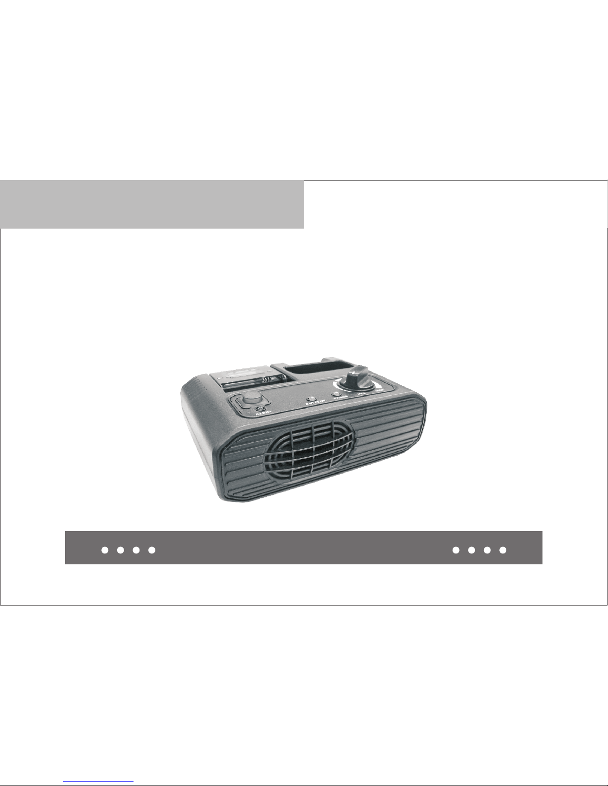
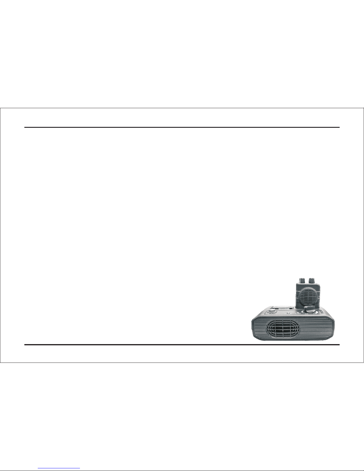
• This manual contains important safety and operating instructions.
• Before using VP200 Chager/Amplifier, please read all instructions and cautionary
markings on the (1) charger, (2) batteries and (3) pager.
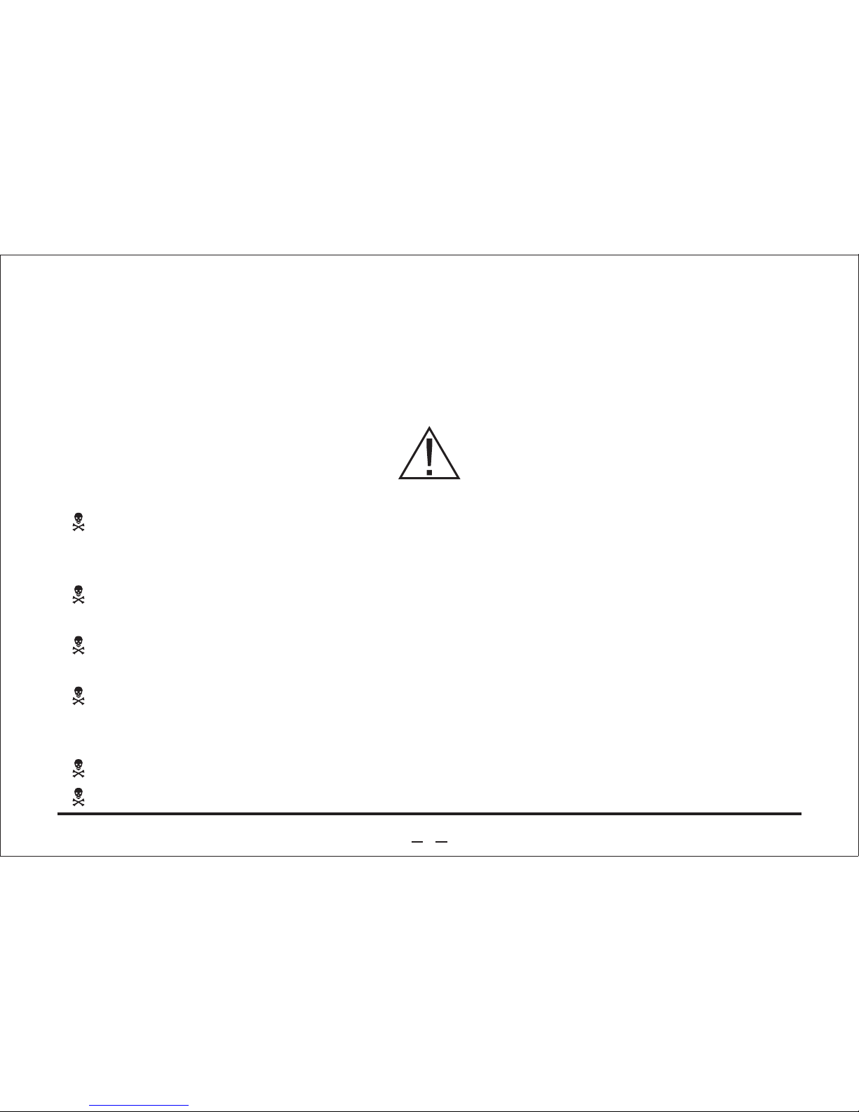
WARNING
Do not expose charger to rain or snow. Use of an attachment not recommended
may result in risk of fire, electrical plug and cord, pull by the plug when
disconnecting the charger.
Make sure the cord is located so that it will not be stepped on, tripped over, or
otherwise subjected to damage or stress.
Do not operate charger with damaged cord or plug – replace them immediately
with an approved power supply only.
Do not operate charger if it has received a sharp blow, been dropped, or otherwise
damaged in any way. Replace damaged charger immediately with approved
charger only.
Do not disassemble charger.
To reduce risk of electrical shock, unplug charger from outlet before cleaning.
•
X
•
X
•
X
•
X
•
X
•
WARNING
IMPORTANT SAFETY INSTRUCTIONS SAVE
THESE INSTRUCTIONS
1
The charger/amplifier models listed below are accessories for VP200 only. The
charger/amplifier could charge batteries while in the VP200 or an individual spare
batteries. Dual colored LED indicators provide information as to which one is being
charged.
All models have two separate charging compartments. One charging compartment
accommodates a pager with the batteries installed, the other one for charging
spare batteries. A charging-status LED indicator is provided for each charging
compartment. These are labeled BATTERY and PAGER. The BATTERY indicator
lights when spare batteries are being charged. The PAGER indicator lights when a
pager with installed batteries, is being charged. If the pager is turned on when it is
installed in the charger/amplifier, reception of a valid page causes the red ALERT
LED to light and the audio message to be heard through the charger/amplifier
speaker. (see Fig.2)
2
CHARGER/AMPLIFIER DESCRIPTION
When a pager is inserted into the charger/amplifier, the setting of the pager's on-off
switch determines the operating mode of the charger/amplifier. When the pager is
turned off, only the charger section of the charger/amplifier is functional. The time
required to completely charge fully discharged batteries in the spare batteries
compartment is approximately 2 hours. Approximately 2 hours of charge time is
required in the main charging compartment. It takes 4 hours to complete both
charge cycles.
To charge 3 batteries , proceed as follow:
1. Place 3 batteries into the battery door; it is locked when you hear an audible
click.
2. The BATTERY indicator light on the charger will begin blinking red. Then the
charging process begins, the BATTERY indicator light will stop blinking and
remain solidly lit. When the charging process is completed, the BATTERY
indicator light wil change in color from red to green.
3. To remove the batteries, open the battery door and lift the batteries out.
Charging-Only Mode Pager Charging Compartmentce
The pager-charging compartment accommodates a VP200. (see Fig.2)
X
X
X
3
GENERAL OPERATION
To charge batteries installed in the pager, proceed as follows:
1. Turn the radio off by rotating the on-off volume knob fully counterclockwise until
a click is heard and the mechanical stop is reached.
2. Press the upper end of the belt clip and slide the pager part way into the charging
compartment.
3. Release the belt clip and continue to slide the page into the charging compartment
until an audible click is heard.
4. When a pager is inserted into the charging compartment, the PAGER indicator
light on the charger will begin blinking red. When the charging process begins,
the PAGER indicator light will stop blinking and remain solidly lit. Then the
charging process is complete, the PAGER indicator light will change in color,
from red to green.
5. To remove the pager from the charger compartment, press the upper end of the
belt clip and slide the pager out of the compartment.
X
X
X
X
X
4
1. If either indicator continues to blink (does not change to solid red) after a pager
or battery has been inserted to the charger, the charging process has not begun.
2. When a pager and batteries are inserted in the charger at the same time, pager
pocket has priority. After pager pocket has completed rapid charging, then the
batteries follows with rapid charging (BATTERY LED solid red).
Otherwise, charging is completed on first come first charged basis. As pager
and battery may be inserted in the charger simultaneously. The first item
inserted, pager or batteries will have priority in the charge cycle. For example,
if the batteries are placed in the battery slot and then the pager in the pager
pocket, the batteries will be charged first. The BATTERY indicator light will be
solidly lit red and the PAGER indicator light will be orange. Once the batteries
are fully charged, the pager will be charged. (see Fig.2)
X
5
NOTE:
External Antenna
The charger/amplifier is supplied with an external antenna for improved fringe area
reception. The external antenna input jack is located on the rear of the charger/
amplifier housing. ( see Fig.1) When the proper antenna is connected, the RF
signal is conducted through a cable to a pair of interconnect pins located in the
charging compartment. When a pager is inserted into the charger compartment,
an electrical path is established between the pager and the charger/amplifier via
the interconnect pins.
Audio Amplifier and External Speakers
The charger/amplifier contains an external speaker jack (2.5watt audio amplifier)
and an internal speaker. An external speaker jack, located on the rear of the
charger/amplifier housing (see Fig.1), allows the user to disable the internal
speaker and route alerting and voice audio to external speakers or devices.
(see P.9 Remote Speaker Audio)
Power Adapters/Cables
Each charger/amplifier model includes an adapter for converting AC voltages from
a commercial power source to the required DC operating voltage.
STANDARD FEATURES
6
Charger/Amplifier Relay Feature
The accessory connector on the back of the charger/amplifier provides a relay
interface for a 2.5 watt un-switched speaker audio with ground, a pair of dry relay
contacts, and a pair of pins to select the operation of the relay timing. (See P.10
Relay Closure Timing Control)
INSTALLATION
1. Connect the power adapter to the charger/amplifier by plugging the DC connector
on the end of the cable into the receptacle marked DC12V on the rear of the unit.
(see Fig.1)
2. Plug the other end of the power adapter into an appropriate AC100~240-volt,
50~60 Hz receptacle.
x
X
7
Desktop Operation
1. Attach the external antenna shipped with the charger/amplifier on the antenna
connector on the back of the unit. (see Fig.1)
2. Select the proper function switch setting on the pager, if applicable, and rotate
the on-off volume control clockwise to turn the pager on.
3. Insert the bottom of the pager part way into the charging compartment, with the
belt clip down and the speaker facing up.
4. Open the belt clip and slide the pager fully into the charging compartment. When
the pager is properly inserted, the clip snaps, securing the pager into the
compartment.
5. While monitoring the channel or listening to background noise, as described in
the user guide for your pager, adjust the volume control on the charger/amplifier
to obtain a comfortable listening level from the charger/amplifier speaker.
A speaker jack on the rear of the charger/amplifier provides a connection to an
external 4-ohm speaker, if desired. The internal speaker is disconnected when an
external speaker is plugged into the jack.
X
X
X
X
X
CHARGER/AMPLIFIER MODE
8