manuals.online logo
Brands
  1. Home
  2. •
  3. Brands
  4. •
  5. Applied Motion Products
  6. •
  7. DC Drive
  8. •
  9. Applied Motion Products STAC6-Q-H User manual

Applied Motion Products STAC6-Q-H User manual

STAC6
STAC6-Q-H Std Quick Setup Guide
Requirements
▪ Only use a compatible Hazardous Location Certied stepper motor. Consult the factory.
▪ A small at blade screwdriver for tightening the connectors.
▪ A personal computer running Microsoft Windows 7, 8, 10 or XP, 32-bit or 64-bit.
▪ For STAC6-Q-H, ST Congurator™ software, available at: http://www.applied-motion.com/products/software
▪ An Applied Motion programming cable (included).
▪ For more information, the STAC6-Q-H Hardware Manual is available by request by emailing [email protected].
To begin, make sure you have the following equipment:
Step 1
Wire the drive to the AC power source.
(Apply power only after reading the following
safety instructions and Step 3 is completed.)
STAC6x drives accept 94-135VAC
If using an external fuse, we recommend the
following fast-acting fuses:
STAC6x: 6 amp Connecting the Motor
ONLY use a compatible Hazardous Location
Certified step motor. Consult Factory.
Never connect or disconnect the motor
while the power is on.
920-0106 Rev B Sht 1 of 4
Earth Ground
Neutral
Line (Hot)
Step 2
Connecting the Motor
ONLY use a compatible Hazadous Location Certified step motor. Consult Factory.
Never connect or disconnect the motor while the power is on.
Note: it is highly recommended that you use a motor with a shielded cable with the STAC6.
Connection diagram shown below:
A+
A–
B+ B–
4
lead
motor
Red
Blue
Yellow White
4 Leads
A+
A–
B+ B–
8
lead
motor
Series Connected
8 Leads Parallel Connected
A+
A–
B+ B–
8
lead
motor
White
Orange
Brown
Green
Red
Yellow Blue
Black
Orange
Red
Brown
Yellow
Blue Black
White
Green
SHLD
SHLD
4-LEADS 8 LEADS
Safety Instructions
Only qualified personnel are permitted to transport, assemble, commission, and maintain this equipment. Properly qualified
personnel are persons who are familiar with the transport, assembly, installation, commissioning and operation of motors, and
who have the appropriate qualifications for their jobs. The qualified personnel must know and observe the following standards and
regulations:
IEC 364 resp. CENELEC HD 384 or DIN VDE 0100
IEC report 664 or DIN VDE 0110
National regulations for safety and accident prevention or VBG 4
To minimize the risk of potential safety problems, you should follow all applicable local and national codes that regulate the installation
and operation of your equipment. These codes vary from area to area and it is your responsibility to determine which codes should be fol-
lowed, and to verify that the equipment, installation, and operation are in compliance with the latest revision of these codes.
Equipment damage or serious injury to personnel can result from the failure to follow all applicable codes and standards. We do not guar-
antee the products described in this publication are suitable for your particular application, nor do we assume any responsibility for your
product design, installation, or operation.
• Read all available documentation before assembly and commissioning. Incorrect handling of products in this manual can result in injury
and damage to persons and machinery. Strictly adhere to the technical information on the installation requirements.
• It is vital to ensure that all system components are connected to earth ground. Electrical safety is impossible without a low-resistance
earth connection.
• In operation, depending on the degree of enclosure protection, the product can have bare components that are live or have hot surfaces.
Control and power cables can carry a high voltage even when the motor is not rotating.
• Never pull out or plug in the product while the system is live. There is a danger of electric arcing and danger to persons and contacts.
• After powering down the product, wait at least ten minutes before touching live sections of the equipment or undoing connections (e.g.,
contacts, screwed connections). Capacitors can store dangerous voltages for long periods of time after power has been switched off. To be
safe, measure the contact points with a meter before touching.
Be alert to the potential for personal injury. Follow the recommended precautions and safe operating practices. Safety notices in this manual
provide important information. Read and be familiar with these instructions before attempting installation, operation, or maintenance. The
purpose of this section is to alert users to possible safety hazards associated with this equipment and the precautions that need to be taken
to reduce the risk of personal injury and damage to the equipment.
Failure to observe these precautions could result in serious bodily injury, damage to the equipment ,or operational difficulty.
Additional Information:
IN/OUT 1 Connector
Step 3
Front View
X COMMON
X7 / CW Limit
X3 / Enable
X5
X4 / Alarm Reset
Analog IN-
Analog IN+
X2 / DIR-
X2 / DIR+
X1 / STEP +
X1 / STEP -
GND
GND
+5V OUT
Y COMMON
Y3 / FAULT
Y2 / MOTION
Y1 / BRAKE
18
17
16
15
14
13
12
11
10
9
8
7
6
5
4
2
3
1
19
20
21
22
23
24
25
X6 / CCW Limit
IN/OUT 1
+5V OUT
+12V OUT
GND
GND
encoder Z+ (5)
NC (10)
encoder B- (4)
NC (9)
encoder B+ (3)
NC (13)
NC (14)
SHLD (15)
(12) NC
(11) NC
(6) encoder Z-
(1) encoder A+
(7) +5VDC 200mA
(2) encoder A-
(8) GND
Connect the Encoder (optional)
Wire the drive’s I/O (optional, dependent upon drive type)
920-0106 Rev B Sht 2 of 4
Over-Current Protection
The STAC6 has hardware over-current detection circuits that protect the drive against “phase to ground” and “phase to phase” motor shorts.
These circuits directly disable the amplifier in a rapid fashion to prevent damage to the driver circuitry.
Typically, the over-current circuitry will react to an over-current condition in 3 to 5 micro-seconds. For a short occurring in a motor, the mo-
tor leads provide enough resistance and inductance to keep the peak current from exceeding the peak rating of the power transistors during
this time period. The motors used with the STAC6 should include 10 foot minimum cables.
In essence the motor/cable system is a part of the over-current circuitry. If the drive is directly shorted with a very
short wire, this condition may cause current conditions that exceed the peak current rating of our power transistors
and therefore could weaken or cause failure in the drive power devices.
Repetitive short circuits also risk damage to the drive. If a short circuit fault occurs, please power off the drive and
investigate carefully before restoring power.
Mounting the Drive
You can mount your drive on the wide or the narrow side of the chassis using #6 screws. If possible, the drive should be securely fastened
to a smooth, flat metal surface that will help conduct heat away from the chassis. If this is not possible, then forced airflow from a fan may be
required to prevent the drive from overheating.
Installation orientation: The STAC6-Q-H drive is ONLY to be installed standing vertical with motor connections on
top).
• Never use your drive in a space where there is no air flow or where other devices cause the surrounding air to be
more than 55°C.
• Never put the drive where it can get wet or where metal or other electrically conductive particles can get on the
circuitry.
• Always provide air flow around the drive. When mounting multiple STAC6 drives near each other, maintain at least
one half inch of space between drives.
Schedule of Limitations:
• Suitability of the use of these drives with ANY stepper motor shall be determined in the end product evaluation.
• This drive does not provide motor overload protection. The maximum current available to the stepper motor is
4.24 A rms (6 Amps peak). Any consideration for stepper motor over¬load protection should be evaluated in the
end product.
• The equipment shall be installed in an enclosure that provides a degree of protection not less than IP54 in accor-
dance with IEC/EN 60079-15 which is accessible only with use of a tool.
• These components have been judged on the basis of the creepages and clearances required in clause 6.4 of IEC/
EN 60079-15 4th Edition.
• The sealed device tests were conducted on mechanical sealed relay based on the relay service temperature of
-40°C to 101.4°C.
• The relay service temperature of 101.4°C was determined during the temperature test on the Model STAC6-Q-H
Stepper Drive at ambient temperature of 55°C.
The STAC6 contains electrostatically sensitive components that can be damaged by incorrect handling. Discharge yourself before touching
the product. Avoid contact with high insulating materials (artificial fabrics, plastic film, etc.). Place the product on a conductive surface.
During operation keep all covers and cabinet doors shut. Otherwise, there are deadly hazards that could possibility cause severe damage to
health or the product.
920-0106 Rev B Sht 3 of 4
Electrical Ratings:
Input Power: 120Vac, 1 Phase, 1.67A (rms)
Output Power: 120Vdc, 1 Phase, 4.24A (rms), Continuous Duty Rating
Input/Output Signal Connections: 5/12Vdc, 10/100mA, electrically isolated
Markings:
Applied Motion Products, Inc.
404 Westridge Dr
Watsonville, CA 95076
IECEx Cert Number: IECEx UL 15.0067U
Ex nA nC IIB Gc
-40°C < Ta < +55°C
ATEX Cert Number: DEMKO 15 ATEX 1505U II 3 G
USA: Class 1, Zone 2, AEx nA nC IIB; Class 1, Division 2, Groups C & D
Canada: Class 1, Zone 2, Ex nA nC IIB Gc “U”; Class 1, Division 2, Groups C & D
If you have any questions or comments, please call
Applied Motion Products Customer Support:
(831) 761-6555, or visit us online:
www.applied-motion.com.
404 Westridge Dr.
Watsonville, CA 95076
Tel: 831-761-6555
www.applied-motion.com STAC6-Q-H Quick Setup Guide
8/12/2020
920-0106 Rev B Sht 4 of 4
Mating Connector
(Type)
Manufacturer and P/N Required Wiring
Motor (5-position, screw terminal) Phoenix Contact 1757048 (included) solid or stranded CU, minimum
-50°C to 125°C 250V wire, 14
AWG -12 AWG, 1 conductor per
terminal, stripping length 7 mm,
tightening torque 0.5 Nm - 0.6 Nm.
AC Power (3-position, screw
terminal)
Phoenix Contact 1767012
(included)
solid or stranded CU, minimum
-50°C to 125°C 250V wire, 16
AWG - 12 AWG, 1 conductor per
terminal, stripping length 7 mm,
tightening torque 0.5 Nm - 0.6 Nm.
RS485 Logic (3-position, screw
terminal)
Phoenix Contact 1827622
(included)
solid or stranded CU, minimum
-50°C to 125°C 250V wire, 20
AWG - 16 AWG, 1 conductor per
terminal, stripping length 7 mm,
tightening torque 0.2 Nm - 0.25
Nm.
IN/OUT1 (DB-25 male) Norcomp 171-025-103L001 connector,
Mouser 40-9725HS shell kit
-
Encoder (HD-15 male)
Norcomp 180-015-102-001 connector,
AMP 5-748678-1 shell kit -
Mating Connectors and Accessories
Other Applied Motion Products DC Drive manuals

Applied Motion Products 3540 MO User manual

Applied Motion Products

Applied Motion Products 3540 MO User manual

Applied Motion Products 2035XD User manual

Applied Motion Products

Applied Motion Products 2035XD User manual

Applied Motion Products PDO 3540 User manual

Applied Motion Products

Applied Motion Products PDO 3540 User manual

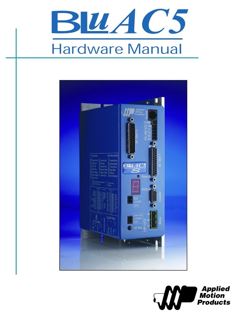
Applied Motion Products BLuAC5 User manual

Applied Motion Products

Applied Motion Products BLuAC5 User manual

Applied Motion Products PDO 2035 User manual

Applied Motion Products

Applied Motion Products PDO 2035 User manual

Applied Motion Products STAC5 Series User manual

Applied Motion Products

Applied Motion Products STAC5 Series User manual

Applied Motion Products STR2M User manual

Applied Motion Products

Applied Motion Products STR2M User manual

Applied Motion Products STR2 User manual

Applied Motion Products

Applied Motion Products STR2 User manual

Applied Motion Products STR4 User manual

Applied Motion Products

Applied Motion Products STR4 User manual

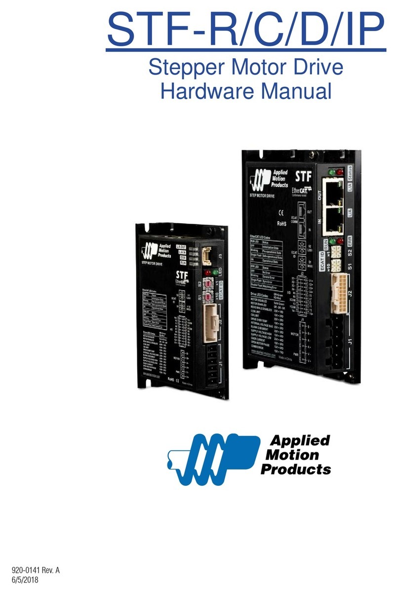
Applied Motion Products STF-R Series User manual

Applied Motion Products

Applied Motion Products STF-R Series User manual

Applied Motion Products ST5-IP User manual

Applied Motion Products

Applied Motion Products ST5-IP User manual

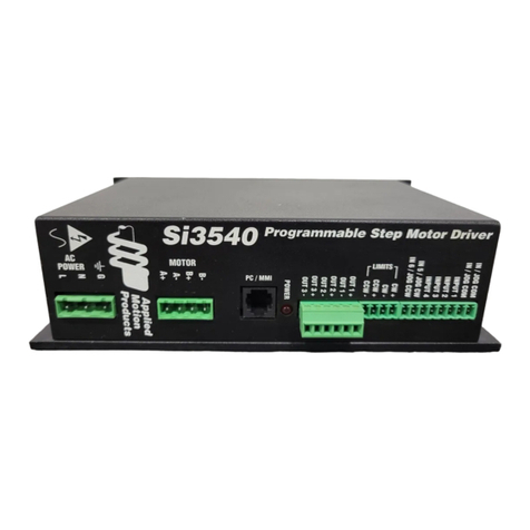
Applied Motion Products Si3540 User manual

Applied Motion Products

Applied Motion Products Si3540 User manual

Applied Motion Products Si5580 User manual

Applied Motion Products

Applied Motion Products Si5580 User manual

Popular DC Drive manuals by other brands

Power Electronics SD700 Series manual

Power Electronics

Power Electronics SD700 Series manual

Danfoss HDU-SF Service guide

Danfoss

Danfoss HDU-SF Service guide

Arroyo Instruments LaserSource 4400 Series user manual

Arroyo Instruments

Arroyo Instruments LaserSource 4400 Series user manual

Selve Commeo SE Pro-RC quick start guide

Selve

Selve Commeo SE Pro-RC quick start guide

Danfoss VLT Flow Drive FC 111 Programming guide

Danfoss

Danfoss VLT Flow Drive FC 111 Programming guide

Rtelligent R60-IO user manual

Rtelligent

Rtelligent R60-IO user manual

SOMFY Sonesse 30 RS485 quick start guide

SOMFY

SOMFY Sonesse 30 RS485 quick start guide

TPM STP-M112 user manual

TPM

TPM STP-M112 user manual

Danfoss VLT AutomationDrive FC 301 operating instructions

Danfoss

Danfoss VLT AutomationDrive FC 301 operating instructions

GFA ELEKTROMAT SI 40.15-40,00 installation instructions

GFA

GFA ELEKTROMAT SI 40.15-40,00 installation instructions

Leadshine Technology DCS810V2 user manual

Leadshine Technology

Leadshine Technology DCS810V2 user manual

GFA ELEKTROMAT ST 80.24-50,00 installation instructions

GFA

GFA ELEKTROMAT ST 80.24-50,00 installation instructions

Lenze L-force LCU Mounting instructions

Lenze

Lenze L-force LCU Mounting instructions

SOMFY Sunea 40 Solar io instructions

SOMFY

SOMFY Sunea 40 Solar io instructions

HP Ultrium Drive Configuration guide

HP

HP Ultrium Drive Configuration guide

SEW-Eurodrive MOVITRAC B System manual

SEW-Eurodrive

SEW-Eurodrive MOVITRAC B System manual

Emerson EV3150B Application guidelines

Emerson

Emerson EV3150B Application guidelines

Stanley SCH20 Original instructions

Stanley

Stanley SCH20 Original instructions

manuals.online logo
manuals.online logoBrands
  • About & Mission
  • Contact us
  • Privacy Policy
  • Terms and Conditions

Copyright 2025 Manuals.Online. All Rights Reserved.