manuals.online logo
Brands
  1. Home
  2. •
  3. Brands
  4. •
  5. Applied Motion Products
  6. •
  7. DC Drive
  8. •
  9. Applied Motion Products BLuAC5 User manual

Applied Motion Products BLuAC5 User manual

22
22
2
BLuAC5 Hardware ManualBLuAC5 Hardware Manual
BLuAC5 Hardware Manual
33
33
3
BLuAC5 Hardware ManualBLuAC5 Hardware Manual
BLuAC5 Hardware Manual
ContentsContents
ContentsContents
Contents
Safety Instructions ................................................................................................. 5
Introduction ......................................................................................................... 6
Block Diagram...................................................................................................................6
Getting Started ..................................................................................................... 7
Status & Error Display LEDs ....................................................................................... 9
Serial Comm Tx & Rx LED ......................................................................................... 9
Bus voltage indication LED ......................................................................................... 9
Seven Segment Display Error codes .......................................................................... 9
Seven Segment Display Status codes ...................................................................... 10
Regeneration LED .................................................................................................... 10
Connecting to the PC using RS-232 ............................................................................ 11
Connecting to a host using RS-485 ............................................................................. 12
A Short tutorial on RS-485 & RS-422 .............................................................................. 12
4-wire RS-485/422 Network...................................................................................... 13
Getting and Connecting a RS-485 4-wire adaptor to your PC................................... 13
2-wire RS-485 Network............................................................................................. 14
Getting and Connecting a RS-485 2-wire adaptor to your PC................................... 14
BeforeYou connect the servo drive to your system -................................................. 14
Connecting the AC Power Input ................................................................................. 15
24Volt Controller Input (Keep Alive).......................................................................... 15
Connecting Single Phase AC input (90-260VAC) ............................................................ 16
Connecting 3-Phase AC input (90-260VAC).................................................................... 16
Connecting DC input (100-367VDC) .............................................................................. 16
Connecting the Motor ............................................................................................ 17
Connecting the Encoder & Hall Sensors ....................................................................... 18
Encoder Pinout ......................................................................................................... 18
Connecting a Single-Ended Encoder ........................................................................ 18
Connecting Single-Ended Hall Sensors .................................................................... 18
Connecting Input Signals ........................................................................................ 19
IN/OUT 1 I/O Connector ........................................................................................... 19
With Expanded I/O (IN/OUT 2) ................................................................................. 19
IN/OUT1 & IN/OUT 2 Connector Pinout Diagrams .................................................. 19
High Speed Digital Inputs................................................................................................ 20
Using High Speed Inputs with 12-24Volt Signals...................................................... 20
Using Mechanical Switches at 24Volts. .................................................................... 21
Connecting to PLC with Sourcing (PNP) Outputs ..................................................... 21
Connecting to PLC with Sinking (NPN) Outputs ....................................................... 21
Standard Digital Inputs ........................................................................................... 22
Single Ended Inputs ........................................................................................................ 22
What is COM? .......................................................................................................... 22
User Out 24V supply................................................................................................. 22
Digital Input Connection Examples ........................................................................... 23
Connecting Limit Switches to the BLuAC5 Drives ........................................................... 24
BLuAC5Limit Input diagram ..................................................................................... 24
Wiring a Mechanical Limit Switch.............................................................................. 24
Wiring a Limit Sensor................................................................................................ 24
Analog Inputs ...................................................................................................... 25
Three dedicated purposes: ....................................................................................... 25
Basic Specifications:................................................................................................. 25
Wiring a controller with differential output as a single ended input ........................... 26
Wiring a controller with differential output to differential input................................... 26
Wiring a potentiometer to a single ended input ........................................................ 26
Programmable Outputs ........................................................................................... 27
Encoder Outputs ............................................................................................................. 28
44
44
4
BLuAC5 Hardware ManualBLuAC5 Hardware Manual
BLuAC5 Hardware Manual
BLuAC5 Expanded I/O board (IN/OUT 2) ......................................................................... 29
Single Ended Inputs ........................................................................................................ 29
What is COM? .......................................................................................................... 29
Connecting to the Aux Analog Input ................................................................................ 31
ProgrammableOutputs ................................................................................................... 32
Recommended AMP Motors ..................................................................................... 33
Alpha A Series.......................................................................................................... 33
Alpha M Series ......................................................................................................... 33
Alpha N Series.......................................................................................................... 33
Other Supplier's Motors................................................................................................... 33
Setting Drive Current Limits ..................................................................................... 34
What is “Peak Current Limit”? ................................................................................... 34
Using DC Brushed Motors ........................................................................................ 35
Servo Drive Regeneration ........................................................................................ 36
Mounting the Drive ................................................................................................ 37
BLuAC5 (all models) ................................................................................................ 37
Mechanical Outlines .............................................................................................. 38
Technical Specifications ......................................................................................... 39
55
55
5
BLuAC5 Hardware ManualBLuAC5 Hardware Manual
BLuAC5 Hardware Manual
Safety InstructionsSafety Instructions
Safety Instructions
Only qualified personnel are permitted to transport, assembly, commission, and maintenance this equip-
ment.Properly qualified personnel are persons who are familiar with the transport, assembly, installation,
commissioning and operation of motors, and who have the appropriate qualifications for their jobs.The
qualified personnel must know and observe the following standards and regulations:
IEC 364 resp.CENELEC HD 384 or DIN VDE 0100
IEC report 664 or DINVDE 0110
National regulations for safety and accident prevention orVBG 4
To minimize the risk of potential safety problems, you should follow all applicable local and national codes
that regulate the installation and operation of your equipment. These codes vary from area to area and it
is your responsibility to determine which codes should be followed, and to verify that the equipment,
installation, and operation are in compliance with the latest revision of these codes.
Equipment damage or serious injury to personnel can result from the failure to follow all appli-
cable codes and standards. We do not guarantee the products described in this publication are
suitable for your particular application, not do we assume any responsibility for your product
design, installation, or operation.
• Read all available documentation before assembly and commissioning.Incorrect handling of products in
this manual can result in injury and damage to persons and machinery.Strictly adhere to the technical
information on the installation requirements.
• It is vital to ensure that all system components are connected to earth ground.Electrical safety is
impossible without a low-resistance earth connection.
•The BLUAC5 contains electrostatically sensitive components that can be damaged by incorrect han-
dling.Discharge yourself before touching the product.Avoid contact with high insulating materials (artifi-
cial fabrics, plastic film, etc.).Place the product on a conductive surface.
• During operation keep all covers and cabinet doors shut.Otherwise, there are deadly hazards that could
possibility cause severe damage to health or the product.
• In operation, depending on the degree of enclosure protection, the product can have bare components
that are live or have hot surfaces.Control and power cables can carry a high voltage even when the
motor is not rotating.
• Never pull out or plug in the product while the system is live.There is a danger of electric arcing and
danger to persons and contacts.
• After powering down the product, wait at least ten minutes before touching live sections of the equip-
ment or undoing connections (e.g., contacts, screwed connections).Capacitors can store dangerous
voltages for long periods of time after power has been switched off.To be safe, measure the contact
points with a meter before touching.
Be alert to the potential for personal injury.Follow the recommended precautions and safe operating
practices included with the alert symbols.Safety notices in this manual provide important information.
Read and be familiar with these instructions before attempting installation, operation, or maintenance.
The purpose of this section is to alert users to possible safety hazards associated with this equipment
and the precautions that need to be taken to reduce the risk of personal injury and damage to the equip-
ment.Failure to observe these precautions could result in serious bodily injury, damage to the equipment,
or operational difficulty.
66
66
6
BLuAC5 Hardware ManualBLuAC5 Hardware Manual
BLuAC5 Hardware Manual
IntroductionIntroduction
Introduction
Thank you for selecting an Applied Motion Products motor control. We hope our dedication
to performance, quality and economy will make your motion control project successful.
If there's anything we can do to improve our products or help you use them better, please
call or fax. We'd like to hear from you. Our phone number is (800) 525-1609 or you can
reach us by fax at (831) 761-6544.You can also email suppor[email protected].
BLuAC5 Features
• Digital servo motor driver in complete fully featured package
• Operates directly from a 100 to 260 Volt AC input, single phase or three phase
• Operates in torque, velocity or position mode
• Accepts analog signals, digital signals and RS-232/485 serial commands
• Motor current to 15.0 amps peak, 5.0 amps continuous
• Seven optically isolated digital inputs (15 inputs with expanded I/O board)
• Three optically isolated digital outputs (7 outputs with expanded I/O board)
• ±10 volt analog input for position, speed and torque control
• 0-5V aux analog input
Block Diagram
motor
encoder
to RS-485 host
RS-485
IGBT
PWM
Power
Amplifier
User Out 24 VDC
X1/STEP/PWM
X2/DIR
X3/SVEN
X4/ALMRST
X5
X6/CCWLMT
X7/CWLMT
to PC
ANALOG+
ANALOG–
Y1/BRAKE
Y2/INPOSN
Y3/ALARM
RS-232 Optical
Isolation
ENCODER OUT
Line
Drivers
DSP
Optical
Isolation
Internal
Logic
Supply
AC Input
Power
Converter
100 - 260 VAC
DC Bus LED
Internal
Regen
Clamp
External Regen Resistor
External Brake Resistor
Input 24 VDC
Regen LED
Seven Segment
Status Display
Rx Status LED
Tx Status LED
77
77
7
BLuAC5 Hardware ManualBLuAC5 Hardware Manual
BLuAC5 Hardware Manual
Getting StartedGetting Started
Getting Started
This manual describes the use of three different drive models. What you need to know and
what you must have depends on the drive model. For all models, you must have the follow-
ing:
• a compatible servo motor
• cables to connect the motor to the drive. If you are using an Applied Motion
“Alpha” motor, use BLUENC and BLMTR cables (one of each).
• a small flat blade screwdriver for tightening the connectors (included).
• a personal computer running Microsoft Windows 95, 98, NT, Me, 2000 or XP.
• The Applied Motion CD that was included with your BLu servo drive
• An Applied Motion programming cable (included)
If you’ve never used a BLu servo before
, you’ll need to get familiar with the drive and the
set up software before you try to deploy the system in your application. We strongly recom-
mend the following:
1. Install the
QuickTuner
™ software from the CD.
2. Launch the software by clicking Start...Programs...Applied Motion
Products...QuickTuner.
3. Connect the drive to your PC using the programming cable supplied.
4. Connect the drive to the AC power source (may be switched).
5. Connect the drive to the motor.
6. Apply power to the drive.
7. Follow the instructions in the
QuickTuner
™ manual. (On the CD)
The connectors and other points of interest are illustrated on the next page. Depending on
your drive model and application, you’ll need to make connections to various parts of the
drive. These are detailed later in the manual.
88
88
8
BLuAC5 Hardware ManualBLuAC5 Hardware Manual
BLuAC5 Hardware Manual
DC Bus
Motor Encoder IN / OUT 1
IN / OUT 2
PC/MMI
RS-485/422
C B A
GND
TX-
TX+
RX-
RX+
COMM
Status
Regen
GND
+24VDC
Input
320V pk
User Out
+24VDC
GND
CLAMP RES
EXT
BUS
BRAKING
L1
L2/N
L3
AC POWER
G
Error Codes
Position Limit
CCW Limit
CW Limit
Over Temp
Over Voltage
Under Voltage
Over Current
Current Limit
Hall Bad
Encoder Bad
Memory Failed
Regen Failed
Comm Error
Position Mode
Velocity Mode
Torque Mode
Step Mode
Operating Modes
Front View
X COMMON
X7/ CWLimit
X3 / Servo Enable
X5
X4 / Alarm Reset
Analog IN-
Analog IN+
X2 / DIR-
X2 / DIR+
X1 / STEP / PWM+
X1 / STEP / PWM-
GND
GND
A+
A-
B+
B-
Z+
Z-
+5V OUT
Y COMMON
Y3 / ALARM
Y2 / INPOSN
Y1 / BRAKE
18
17
16
15
14
13
12
11
10
9
8
7
6
5
4
2
3
1
19
20
21
22
23
24
25
Encoder
Outputs
X6/ CCWLimit
18
17
16
15
14
13
12
11
10
9
8
7
6
5
4
2
3
1
19
20
21
22
23
24
25
+5V
Out 1-
Out 2+
Out 1+
Ain Com
N/C
Ain 1
IN 8-
COM
IN 5
IN 6
IN 7+
IN 8+
IN 7-
IN 4
IN 1
COM
IN 2
COM
IN 3
Out 2-
Out 3+
Out 3-
Out 4+
Out 4-
enabled when
flashing
Drive Disabled
Si Mode
INT
rotating segment indicates Q
program running.
IN/OUT 2
IN/OUT 1
DB-25 connector #1
•
digital inputs
•
digital outputs
•
analog inputs
•
encoder output
HD-15 connector
•
motor feedback
screw terminal
plugable connector
•
motor
plugable screw
terminal connector
•
RS-485 port
comm status LEDs
•
Rx (Green)
•
Tx (Amber)
RJ11 connector
•
RS-232 port
Always use the blue & white Applied Motion
screwdriver to tighten the screw terminal connectors.
Larger screwdrivers may remove the plastic dimples
that prevent the screws from falling out.
plugable screw
terminal connector
•
AC input 100-260VAC
•
DC input 90-367VDC
plugable screw
terminal connector
•
Dynamic Braking Resistor
plugable screw
terminal connector
•
External Regen Resistor
DB-25 connector #2
Expansion I/O
•
digital inputs
•
digital outputs
•
analog input
Status LED
•
Regen
Seven Segment
LED
•
status codes
•
error Codes
Status LED
•
DC Bus Voltage
present
plugable screw
terminal connector
•
User 24 volt output
plugable screw
terminal connector
•
24 volt (Keep Alive)
input
Standard on BLuAC5-Si
Option on -S, -Q
99
99
9
BLuAC5 Hardware ManualBLuAC5 Hardware Manual
BLuAC5 Hardware Manual
Status & Error Display LEDsStatus & Error Display LEDs
Status & Error Display LEDs
Serial Comm Tx & Rx LED
Indicates that data is being received or transmitted through the RS-232 or RS-485 serial
ports. Green indicates “Receiving”. Amber indicates “Transmitting”
Bus voltage indication LED
Indicates when there is DC Bus voltage present on the drive.The servo drive cover should
not be removed when this LED is illuminated. (See “WARNINGS” at end of manual)
Seven Segment Display Error codes
Note: codes with a ”*” indicate drive has faulted and flash at a 0.5 second rate.
*Over Current: The Motor phase current has exceeded the 20 amps (RMS).The drive will be faulted.
*UnderVoltage: The DC Bus voltage has gone below 100Volts.
*OverVoltage: The DC Bus voltage exceeded 400Volts.The drive will be faulted after this error.
*Regeneration Error: While attempting to “dump”power into the regeneration shunt resistor the device
limits were reached (based on settings) or, there is no regeneration shunt resistor attached.
*OverTemperature: The Drive PCB temperature has exceeded 75° C.This will cause the drive to fault
and cannot be cleared until the temperature drops below the limit.
CW Limit: The Clockwise limit has been triggered.This will depend on the CCW/CW Input settings.Use
“DL” Host command or QuickTuner™ “I/O” panel to enable usage.
CCW Limit: The Counter Clockwise limit has been triggered.This will depend on the CCW/CW Input
settings.Use “DL” Host command or QuickTuner™ “I/O” panel to enable usage.
*Position Limit Error: Indicates the Servomotor has exceeded the“Position Limit”value, set by
QuickTuner™ “Drive” panel or the “PF”Host command.
Current Limit: The Motor phase current has exceeded the “Peak” current time limit (As set by the CP
Host command or QuickTuner™).
*Hall Pattern Bad: Indicates that the Hall sensor (commutation track) inputs are incorrect.Drive only
accepts 120° Hall sensor patterns.Could also indicate a failed sensor.
*Encoder Failure: Indicates that the Encoder inputs are not providing the correct states.This feature
can be enabled or disabled using the QuickTuner™ Setup utility, “Single Ended”checkbox.
Memory Fault: When reading or writing to “Flash”memory an error occurred.This is an indicator of
memory problems that are typically induced with too many write cycles (>100,000).
Serial Comm Error: Indicates a Serial Communication error.This error is also indicated by the Comm
Tx and Rx LEDs flashing an alternating pattern.This could result from a number of different conditions
such as incorrect Baud Rate, electrical noise or faulty wiring.
1010
1010
10
BLuAC5 Hardware ManualBLuAC5 Hardware Manual
BLuAC5 Hardware Manual
Seven Segment Display Status codes
Regeneration LED
This LED indicates when the drive is actively applying the regeneration clamp.The clamp is
the internal circuitry that shunts the DC bus to a power resistor.The power resistor can be
either internal or external. (See “Servo Drive Regeneration” in this manual for more details)
Positioning Mode: The drive is in Positioning Mode.This is the mode used when performing “point to
point”moves.
Velocity Mode: The drive is inVelocity Mode.This is the mode used when “Jogging”or Analog com-
mandedVelocity.
Torque Mode: The drive is inTorque Control Mode.This is the mode used for Analog commanded
Torqueoperation.
Step & Direction Mode: The drive is in Step and Direction Control Mode.This is the mode used for
“Encoder Following” or Positioning using Step and Direction input.
Si Positioning: When in Si Programmer mode or running an Si program this code typically appears.
Drive Disabled: The drive output is disabled.
Q Program Running: An outside segment will be rotating around the display.The rotate rate is about
0.2 seconds per segment.
Drive Start-up test pattern: This pattern is displayed for a short period of time at drive start-up.
1111
1111
11
BLuAC5 Hardware ManualBLuAC5 Hardware Manual
BLuAC5 Hardware Manual
Connecting to the PC using RS-232Connecting to the PC using RS-232
Connecting to the PC using RS-232
• Locate your computer within 6 feet of the BLu servo drive.
•Your drive was shipped with a black adapter plug. It has a telephone style jack at one end
and a larger 9 pin connector at the other . Plug the large end into the COM1 serial port of
your PC. Secure the adapter with the screws on the sides. If the COM1 port on your PC is
already used by something else, you may use the COM2 port for the drive. On some PCs,
COM2 will have a 25 pin connector that does not fit the black adapter plug. If this is the
case, and you must use COM2, you will have to purchase a 25 to 9 pin serial adapter at
your local computer store.
•Your drive was also shipped with a 7 foot telephone line cord. Plug one end into the
adapter you just attached to your PC, and the other end into the RS-232 jack on your drive.
If you need to locate your drive farther from the PC, you can replace the 7 foot phone cord
with a longer one. Do not exceed 50 feet.
• If your PC does not have an RS-232 COM port but provides a USB connection, there are
many USB to RS-232 adaptors available that will do the trick.
Never connect a BLu servo drive to a telephone circuit. It uses the same connectors and cords as
telephones and modems, but the voltages are not compatible.
(5) GND
(4) Drive TX (3) +5 Volt output for MMI & HUB
(2) Drive RX
2
35
6
DB9 to RJ11 Adaptor Pin assignments
DB9 female Signal Name RJ11 Signal Name
2RX4TX
3TX2RX
5 GND 5 GND
Servo Drive RJ11
1
(2) PC TX
(3) No Connection (4) PC Rx
(5) PC Ground
1
Adaptor RJ11
6
Adaptor DB9
Front View
Front View
Front View
PC DB9 to
Servo Drive RJ11 Adaptor
NOTE: Pins 1 & 6 are not connected
1212
1212
12
BLuAC5 Hardware ManualBLuAC5 Hardware Manual
BLuAC5 Hardware Manual
Connecting to a host using RS-485Connecting to a host using RS-485
Connecting to a host using RS-485
RS-485/422 allows you to connect more than one drive to a single host PC, PLC or other
computer. It also allows the communication cable to be long (more than 1000 feet). But the
device to which you connect must have an RS-485/422 port.
A ShorA Shor
A ShorA Shor
A Short tutorial on RS-485 & RS-422t tutorial on RS-485 & RS-422
t tutorial on RS-485 & RS-422t tutorial on RS-485 & RS-422
t tutorial on RS-485 & RS-422
There is a bit of confusion on the implementation of the these two serial interface specifica-
tions.RS-485 in the strictest definition is a “2-wire” interface that allows multi-node connec-
tions limited to “Half-duplex” serial communications. Up to 32 nodes that both transmit and
receive can be connected to the network. RS-422 also in the strictest definition is a “4-wire”
point to point connection that allows “Full-duplex” serial communications when connected to
a single node. RS-422 has one node that is the driver or transmitter and up to 10 nodes
that are receivers. RS-422 was not designed for a true multi-node network.
2- wire interfaces require one more significant feature. A network node, master or slave,
must be able to tristate it’s transmitter to allow other nodes to use the network when re-
quired. For high speed baud rates this must be done very quickly to avoid communication
collisions.
4-wire interfaces can go beyond the simple point to point and do multi-node networks if the
slave nodes are capable of tri-stating their transmitters as required in the 2-wire networks.
Some RS-485 devices are set up to do this and can be used in a 4-wire configuration.
On the AMP Servo drives the RS-485 can be implemented with either “2-wire” or “4-wire”.
When using 4-wire it is possible to operated in “Full Duplex” but in practice should be lim-
ited to “Half Duplex”. Half Duplex avoids possible communication collisions. 2-wire is al-
ways limited to Half-duplex. 4-wire implementations can sometimes be easier due to the
greater number of Host RS-232 to RS-485 adaptors that support the 4-wire interface.They
are also easier to use because the Host PC or system does not have to tristate (disable) it’s
transmitter. 2-wire implementations may require special Host adaptors that support “Auto
enable” of the adaptor transmitter.This is because PC software typically doesn’t support tri-
stating the output of the serial adaptors.
In both 2-wire and 4-wire systems one extra wire is always required to connect the
“Grounds” of all the nodes on the network. Even though in both cases the signals are sent
differentially a command ground connection is absolutely required.
One more consideration must not be neglected. Proper cable shielding is a must. High
voltage, high frequency, high current signals that are present on the servo motor cables can
emit a significant amount of electrical interference.Without proper shielding these signals
can disrupt even “noise tolerant” differential line drivers.
NOTE: RS-485 is only available on the -S and -Q drive versions
1313
1313
13
BLuAC5 Hardware ManualBLuAC5 Hardware Manual
BLuAC5 Hardware Manual
4-wire RS-485/422 Network
Our RS-485 implementation is a 4-wire multi-drop network with separate transmit and
receive wires. One pair of wires connect from the host computer'sTX+ and TX- signals to
each drive's RX+ and RX- terminals. Another pair connect the TX+ and TX- drive terminals
to the host computer's RX+ and RX- signals. A common ground terminal is provided on
each drive and can be used to keep all drives at the same ground potential. This terminal
connects internally to the DC power supply return (V-), so if all the drives on the RS-485
network are powered from the same supply it is not necessary to connect the logic
grounds. You should still connect one drive's GND terminal to the host computer ground.
Before wiring the entire system, you'll need to connect each drive individually to the host
computer so that a unique address can be assigned to each drive. Proceed as follows:
(Also see figure #1 below)
1. Connect the drive TX+ to the PC's RX+ terminal.
2. Connect the drive TX- to PC RX-.
3. Connect RX+ to TX+.
4. Connect RX- to TX-.
5. Connect GND to GND.
Getting and Connecting a RS-485 4-wire adaptor to your PC
Model 117701 from Jameco Electronics (800-831-4242) works well. This adaptor is for a
25 pin serial port. If you are like most people and have a 9 pin serial port on your PC, you
will also need to purchase Jameco cable 31721. Connect as follows:
adaptor drive
1 RX+
2 RX-
3 TX-
4 TX+
Set the switches for DCE andTxON,RxON. Don't forget to plug in the DC power adaptor
that comes with the unit.
+RX- +TX- GND +RX- +TX- GND +RX- +TX- GND
to PC TX+
to PC TX-
to PC RX+
to PC RX-
to PC GND
Drive #1 Drive #2 Drive #3
4-Wire multi-drop RS-485 Figure #1
1414
1414
14
BLuAC5 Hardware ManualBLuAC5 Hardware Manual
BLuAC5 Hardware Manual
2-wire RS-485 Network
You can also connect the drive to the Host computer using only a 2-wire interface. In this
case you must first connect the TX+ to the RX+ and the TX- to the RX- on the servo drives
before connecting to the Host adaptor. Usually RS-485 2-wire interfaces are labeled “A” &
“B”. (See figure #2 below)
Getting and Connecting a RS-485 2-wire adaptor to your PC
Model 485-25E from Integrity Instruments (800-450-2001) works well. It comes with every-
thing you need. Connect as follows:
adaptor drive
A TX+/RX+
B TX-/RX-
+RX- +TX- GND +RX- +TX- GND +RX- +TX- GND
to PC TX+/RX+ or A
to PC TX-/RX- or B
to PC GND
Drive #1 Drive #2 Drive #3
2-Wire multi-drop RS-485 Figure #2
Before You connect the servo drive to your system -
With the RS-232 cable connected between your PC and the Servo drive, on your PC, start
the SCL Setup Utility software. Select the proper comm port (1,2,3 or 4) then apply power
to the drive. Press the Caps Lock key. The drives only accept commands in uppercase.
Type RV then press ENTER. If the drive has power and is properly wired, it will respond
with "RV=x". Where x is the firmware version of your drive. If the drive responds, you're
home free: the RS-485 network is functioning.
Next, you must choose an address for this drive. Any of the "low ASCII" characters (many
of which appear above the number keys on a PC keyboard) is acceptable: ! " # $ % & ' ( ) *
+ , - . / 0 1 2 3 4 5 6 7 8 9 : ; < > ? @
To find out what address is in the drive now, type DA then press enter. The drive will re-
spond with DA=x, where x is the address that was last stored. (For example, the response
might be DA=@ or DA=!). To change the address, type DAy, where y is the new address
character, then press ENTER.
To test the new address, type yRV, then press ENTER. For example, if you set the address
to % and want to test that, type %RV. The drive should respond just as it does to RV, the
global revision level request.
Once all the drives have been assigned unique addresses, you can proceed to wire the
whole system together.
1515
1515
15
BLuAC5 Hardware ManualBLuAC5 Hardware Manual
BLuAC5 Hardware Manual
Connecting the AC Power InputConnecting the AC Power Input
Connecting the AC Power Input
The AC input to the servo drive will accept a broad range of variations.The AC source
voltage can range for 90VAC RMS to 260VAC RMS, the Frequency from 50 to 60 Hz and
the phase from single to three phase.
The AC input voltage is the most significant attribute of the AC input to affect the power that
is available from the drive. At lower AC inputs the DC bus voltage is reduced and therefore
will limit performance of higher voltage AC servo motors.As a general rule AC inputs of 120
VAC will permit continuous operation of 500 Watt servo motors while AC inputs of 240VAC
will operate 1K Watt servo motors. It is wise to match as closely as possible the AC input
and the Servo Motor voltage rating.
AMP has a number of servo motors designed to operate at both 120 and 240VAC input
(See list in the BLuAC5 data sheet available on our website)
When available, three phase input is recommended for its lower ripple on the DC bus volt-
age.This saves wear and tear on the DC bus capacitors and spreads out the current on the
AC input rectifiers.
DC voltages can also be connected directly to the AC inputs.The range in this case is
limited to 100 to 367 VDC.
WARNING: Exceeding the DC Bus voltage of 367VDC may cause the internal regen-
eration circuitry to activate.This may result in a drive fault or some cases can result
in drive failure.
24 Volt Controller Input (Keep Alive) The BLUAC5 servo drives offer a 24 volt input that will
supply “Keep Alive” power to the controller section of
the drive. AC power can be removed without shutting
down the servo controller.This function can be used to
maintain motor position information.When AC power is
restored to the drive the servo motor can be re-enabled
and the original position reestablished.
NOTE:When 24 volt input is present and the AC input is removed the drive will display a
“U” error code.
1616
1616
16
BLuAC5 Hardware ManualBLuAC5 Hardware Manual
BLuAC5 Hardware Manual
2.65"
DC Bus
C
B A
Input
320V pk
User Out
+24VDC
GND
CLAMP RES
EXT
BUS
BRAKING
L1
L2/N
L3
AC POWER
G
aile
m
E
rror
Front View
X COMMON
mi
t
Se
rvo Enable
X5
ar
m Reset
X2 / DIR-
X2 / DIR+
X1 / STEP / PWM+
X1 / STEP / PWM-
GND
GND
A+
A-
B+
B-
Z+
Z-
+5V OUT
Y COMMON
Y3 / ALARM
Y2 / INPOSN
Y1 / BRAKE
18
17
16
15
14
13
12
11
10
9
8
7
6
5
4
2
3
1
19
20
21
22
23
24
25
Encoder
Outputs
W
L
imit
18
17
16
15
14
13
12
11
10
9
8
7
6
5
4
2
3
1
19
20
21
22
23
24
25
+5V
Out 1-
Out 2+
Out 1+
Ain Com
N/C
Ain 1
IN 8-
COM
IN 5
IN 6
IN 7+
IN 8+
IN 7-
IN 4
IN 1
COM
IN 2
COM
IN 3
Out 2-
Out 3+
Out 3-
Out
4+
O
ut
enabl
ed
flashing
INT
in
dicates Q
ng
.
IN/OU
T
2
N/
OUT 1
Connecting Single Phase AC input (90-260VAC)
Connecting 3-Phase AC input (90-260VAC)
2.65"
DC Bus
Motor
C B A
320V pk
User Out
+24VDC
GND
CLAMP RES
EXT
BUS
BRAKING
L1
L2/N
L3
AC POWER
G
e
w
D
GND
A+
A-
B+
B-
Z+
Z-
+5V OUT
Y COMMON
Y
3 / ALARM
2
/
INPOSN
B
RAKE
8
13
1
2
1
1
9
20
21
22
23
24
25
Encoder
Outputs
18
17
16
15
14
13
12
11
10
9
8
7
6
5
4
2
3
1
19
20
2
1
2
+5V
Ou
Ou
t
1
Ain C
om
N/C
Ain 1
IN 8-
COM
IN 5
IN 6
IN 7+
IN 8+
IN 7-
IN 4
IN 1
COM
IN 2
COM
IN 3
INT
IN
Connect Earth (Green) to “G”
“Hot” (Black) to “L1”
“Neutral” (White) to “L2/N”
Connect Earth (Green) to “G”
“Phase 1” (Black) to “L1”
“Phase 2” (White) to “L2/N”
“Phase 3” (Red) to “L3”
Connecting DC input (100-367 VDC)
Connect Earth (Green) to “G”
“+V” to “L1”
“-V/GND” to “L2/N”
1717
1717
17
BLuAC5 Hardware ManualBLuAC5 Hardware Manual
BLuAC5 Hardware Manual
Connecting the MotorConnecting the Motor
Connecting the Motor
WARNING: Never connect or disconnect the motor while the power is on.
Applied Motion motor:
To connect an Applied Motion servo motor to your BLu Servo, you'll need a set of mating
cables called the BLUENC and the BLMTR.
Connect the small twist lock motor connector to one end of the BLMTR cable. The other
end of the BLMTR has lead wires that connect to the drive’s screw terminal connector as
follows:
A = red wire
B = white wire
C = black wire
"-" = green wire
Connect the large motor connector to one end of the
BLUENC cable. The other end of the BLUENC plugs
into the BLu servo.
Non-Applied Motion motor:
Connect the motor leads to the screw terminal connector as follows:
A = motor phase A, R or U
B = motor phase B, S or V
C = motor phase C, T or W
"-" = ground wire
Motor
1818
1818
18
BLuAC5 Hardware ManualBLuAC5 Hardware Manual
BLuAC5 Hardware Manual
Connecting the Encoder & Hall SensorsConnecting the Encoder & Hall Sensors
Connecting the Encoder & Hall Sensors
Encoder Pinout
The encoder connections use a HD-15 connector as shown in the pinout. When connect-
ing the Encoder and Hall sensors use high quality shielded cables. Connect cable shield to
the HD-15 connector backshell.
The BLuAC5 servo drive is designed for “Differen-
tial” inputs on both the encoder signals and hall
sensors. It is highly recommended that encoders
with “Differential Line Drivers” be used to provide
maximum noise immunity. Using the BLUENC
cable with AMP servo motors provides the best
opportunity for minimizing connection problems.
encoder Z+ (5)
Hall 1-(10)
encoder B- (4)
Hall 1+ (9)
encoder B+ (3)
Hall 3+ (13)
Hall 3- (14)
NC (15)
(12) Hall 2-
(11) Hall 2+
(6) encoder Z-
(1) encoder A+
(7) +5VDC 200mA
(2) encoder A-
(8) GND
Connecting a Single-Ended Encoder
Single-ended encoders may be connected to the servo drive as shown below. It some
cases this may cause loss of encoder data.Typically the single ended encoders source
impedance is high and cannot drive a terminated transmission line. Because of this single-
ended signals may be more susceptible to “Ground” and induced noise.
Single Ended Encoder
encoder A (3)
GND (1)
+5VDC (4)
encoder B (5)
index (2)
Encoder Connector
(8) GND
(5) Z+
(3) B+
(1) A+
(7) +5V
(4) B-
(6) Z-
(2) A-
NC
NC
NC
3.3k
Vcc
330
Vcc
220
Typical Input
Circuit
NOTE: Not recommend in“High Noise” environments
Connecting Single-Ended Hall Sensors
Single-ended Hall sensors may be connected to the servo drive as shown below. The
output of each Hall sensor must be able to “sink” 10 mA of current in order to properly drive
the hall sensor inputs.Typically “Open Collector outputs are best suited to driving the hall
sensor inputs.
Encoder Connector Pinout
Single Ended Hall Sensors
V or B
U or A
GND
W or C
Encoder Connector
(7) +5V
NC
NC
NC
220
Vcc
220
Typical
Input
Circuit
+5V
(8) GND
Open Collector
Outputs
Vcc
(10) Hall 1-
(9) Hall 1+
(13) Hall 3+
(14) Hall 3-
(12) Hall 2-
(11) Hall 2+
1919
1919
19
BLuAC5 Hardware ManualBLuAC5 Hardware Manual
BLuAC5 Hardware Manual
Connecting Input SignalsConnecting Input Signals
Connecting Input Signals
The BLu servo drives have four types of inputs:
• high speed digital inputs for step & direction or PWM commands, 5 volt logic
• digital inputs for other signals, 12 - 24 volt logic
• analog inputs for torque and speed commands, ±10V
• analog input (0 to 5 volts) on “IN/OUT 2” connector ( available on -S & -Q drives with I/O
Expansion)
IN/OUT 1 I/O Connector
This connector include seven digital inputs, three digital outputs and two analog inputs.
The inputs and outputs are programmable on the drive. A number of the I/O lines are
configurable for either “Dedicated” or “Programmable” operation.
Dedicated Inputs:
CW & CCW Limit: can be used to inhibit motion in a given direction, forcing the motor and
load to travel within mechanical limits.
PWM & DIR: digital signal commanding torque, velocity or position.
Servo Enable: servo is active when closed. Motor is disabled (turns freely) when open.
Alarm Reset: Close this signal momentarily to reset a drive fault (alarm).
Dedicated Outputs:
Brake: Activates or releases a mechanical brake when servo drive is enabled or disabled.
In Position or Moving: Indicates when the servo drive is performing a“Move”.
Alarm or Fault: Indicates when the servo drive has a alarm the has resulted in a fault.
Analog In: analog torque, velocity or position command signal
With Expanded I/O (IN/OUT 2)
The BLuAC5 I/O expansion board adds eight programmable inputs, 4 programmable out-
puts and one analog input on a male DB-25 connector. (Standard on BLuAC5-Si)
Front View
X COMMON
X7/CWLimit
X3 / Servo Enable
X5
X4 / Alarm Reset
Analog IN-
Analog IN+
X2 / DIR /CCW Jog-
X2 / DIR /CCWJog+
X1 / STEP / CW Jog+
X1 / STEP / CW Jog-
GND
GND
A+
A-
B+
B-
Z+
Z-
+5V OUT
Y COMMON
Y3 / ALARM
Y2 / INPOSN
Y1 / BRAKE
18
17
16
15
14
13
12
11
10
9
8
7
6
5
4
2
3
1
19
20
21
22
23
24
25
Encoder
Outputs
X6/CCWLimit
IN/OUT 1
IN/OUT1 & IN/OUT 2 Connector Pinout Diagrams
18
17
16
15
14
13
12
11
10
9
8
7
6
5
4
2
3
1
19
20
21
22
23
24
25
+5V
Out 1-
Out 2+
Out 1+
Ain Com
N/C
Ain 1
IN 8-
COM
IN 5
IN 6
IN 7+
IN 8+
IN 7-
IN 4
IN 1
COM
IN 2
COM
IN 3
Out 2-
Out 3+
Out 3-
Out 4+
Out 4-
IN/OUT 2
Note - this connector is standard on Si
version and only on S and Q versions with
expanded I/O.
2020
2020
20
BLuAC5 Hardware ManualBLuAC5 Hardware Manual
BLuAC5 Hardware Manual
BLU
Servo
Drive
IN/OUT 1
DIR+ DIR+
DIR- DIR-
STEP+
STEP-
STEP+
STEP-
Indexer
with
Differential
Outputs
BLU Servo
Master
Encoder
GND
DIR-
DIR+
STEP-
STEP+
GND
B-
B+
A-
A+
Using High Speed Inputs with 12-24 Volt Signals
Most PLCs don't use 5 volt logic. You can connect signal levels as high as 24 volts to the
STEP and DIR inputs if you add external dropping resistors, as shown below.
• For 12 volt logic, add 820 ohm, 1/4 watt resistors
• For 24 volt logic, use 2200 ohm, 1/4 watt resistors
WARNING: The maximum voltage that can be applied directly to a high speed input terminal is 5
volts. Never apply high voltage AC to an input terminal.
BLU
Servo
Drive
IN/OUT 1
COM DIR-
DIR DIR+
STEP-
STEP STEP+
Indexer
with
Sourcing
Outputs
Connecting to Indexer with Sinking Outputs
(includes Applied Motion Si-1 Indexer)
BLU
Servo
Drive
IN/OUT 1
+5V OUT DIR+
DIR DIR-
STEP+
STEP STEP-
Indexer
with
Sinking
Outputs
High Speed Digital Inputs
The BLuAC5 drives include two high speed inputs called STEP (Pulse) and DIR. They
accept 5 volt single-ended or differential signals, up to 2 MHz. Normally these inputs con-
nect to an external controller that provides step & direction command signals.You can also
connect a master encoder to the high speed inputs for following applications.

Other Applied Motion Products DC Drive manuals

Applied Motion Products PDO 3540 User manual

Applied Motion Products

Applied Motion Products PDO 3540 User manual

Applied Motion Products 3540 MO User manual

Applied Motion Products

Applied Motion Products 3540 MO User manual

Applied Motion Products STAC5 Series User manual

Applied Motion Products

Applied Motion Products STAC5 Series User manual

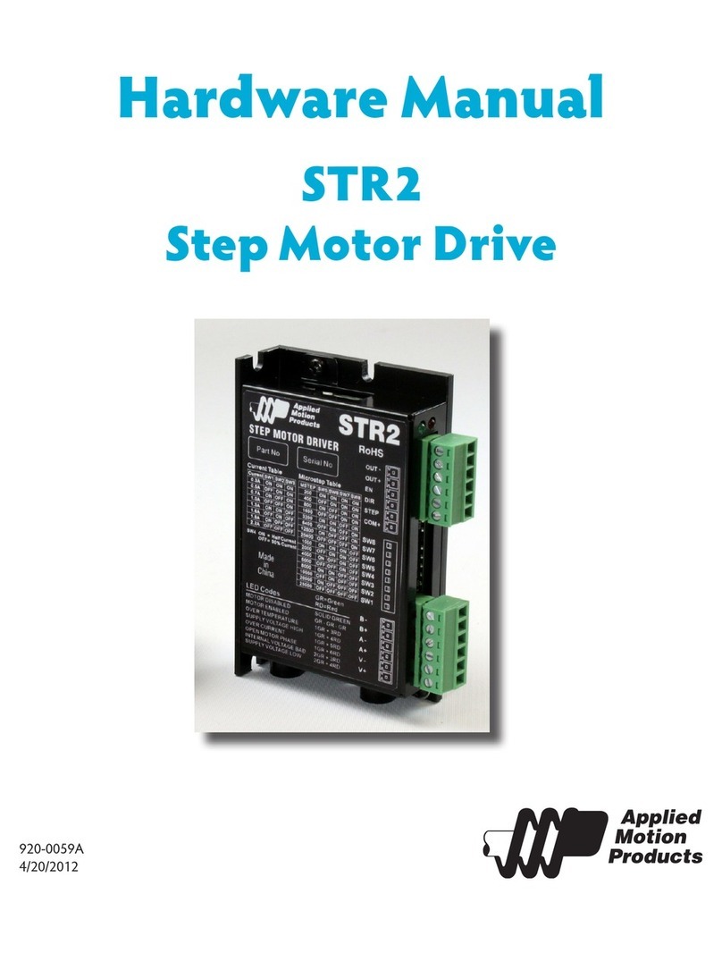
Applied Motion Products STR2 User manual

Applied Motion Products

Applied Motion Products STR2 User manual

Applied Motion Products STAC6-Q-H User manual

Applied Motion Products

Applied Motion Products STAC6-Q-H User manual

Applied Motion Products Si5580 User manual

Applied Motion Products

Applied Motion Products Si5580 User manual

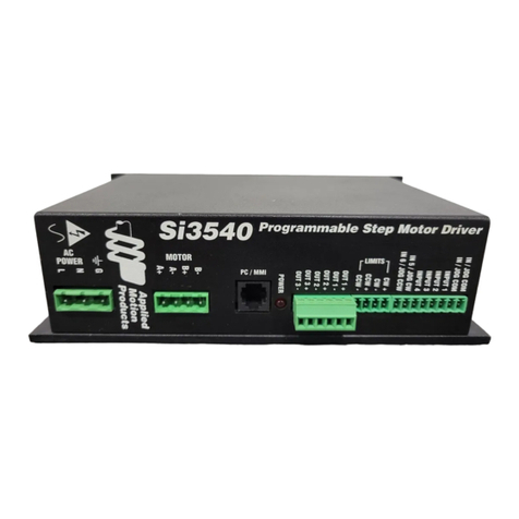
Applied Motion Products Si3540 User manual

Applied Motion Products

Applied Motion Products Si3540 User manual

Applied Motion Products STR2M User manual

Applied Motion Products

Applied Motion Products STR2M User manual

Applied Motion Products ST5-IP User manual

Applied Motion Products

Applied Motion Products ST5-IP User manual

Applied Motion Products 2035XD User manual

Applied Motion Products

Applied Motion Products 2035XD User manual

Applied Motion Products PDO 2035 User manual

Applied Motion Products

Applied Motion Products PDO 2035 User manual

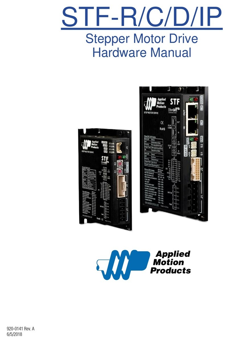
Applied Motion Products STF-R Series User manual

Applied Motion Products

Applied Motion Products STF-R Series User manual

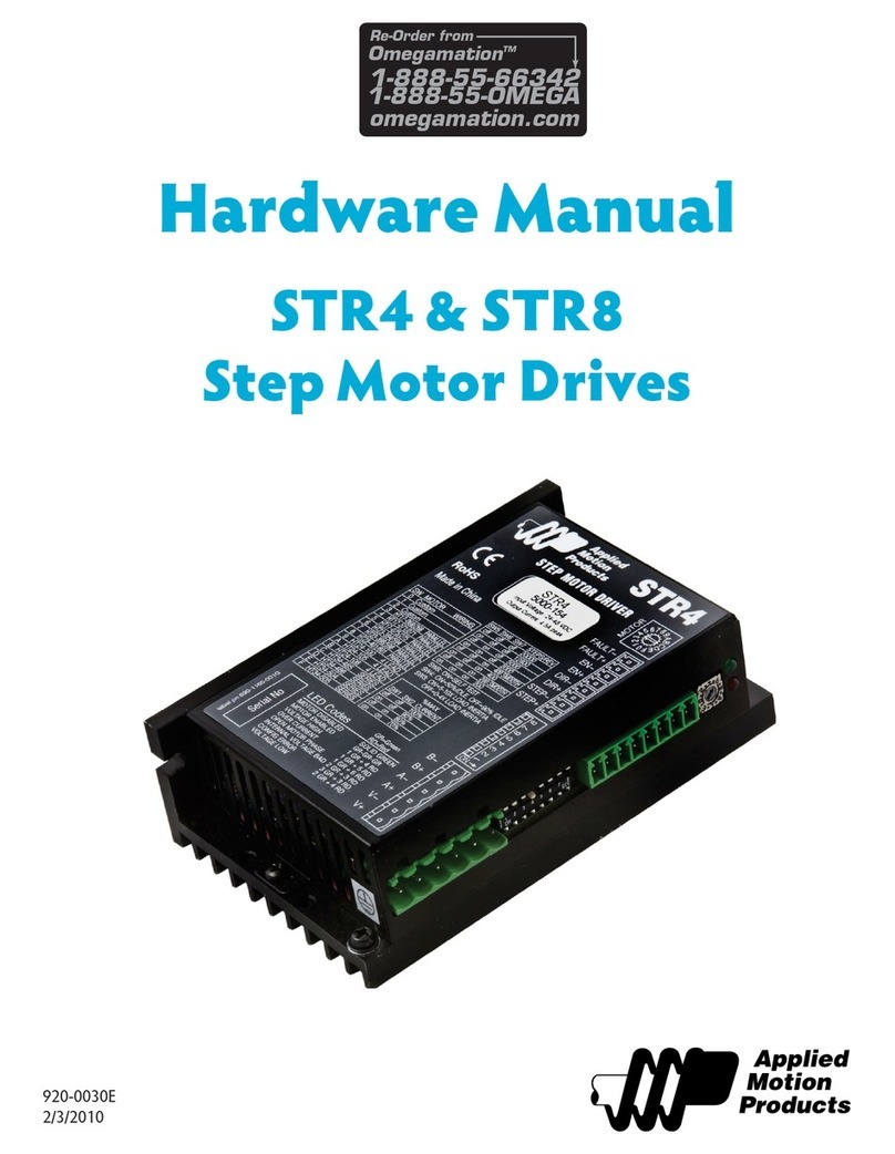
Applied Motion Products STR4 User manual

Applied Motion Products

Applied Motion Products STR4 User manual

Popular DC Drive manuals by other brands

Mitsubishi Electric FR-F740-00023-EC instruction manual

Mitsubishi Electric

Mitsubishi Electric FR-F740-00023-EC instruction manual

HELVAR LL1x150-CR-DA manual

HELVAR

HELVAR LL1x150-CR-DA manual

Sprint Electric 340 product manual

Sprint Electric

Sprint Electric 340 product manual

UNI Geräte MG Series manual

UNI Geräte

UNI Geräte MG Series manual

DeVilbiss QS-5012 Service bulletin

DeVilbiss

DeVilbiss QS-5012 Service bulletin

SEW-Eurodrive MOVIMOT MM D Series Compact operating instructions

SEW-Eurodrive

SEW-Eurodrive MOVIMOT MM D Series Compact operating instructions

LYSON MINIMA ZESTAWM AD installation manual

LYSON

LYSON MINIMA ZESTAWM AD installation manual

Dover Pull Master PH50 Instructions and parts manual

Dover

Dover Pull Master PH50 Instructions and parts manual

YASKAWA Varispeed f7 Technical manual

YASKAWA

YASKAWA Varispeed f7 Technical manual

Mitsubishi Electric FR-D700 Series instruction manual

Mitsubishi Electric

Mitsubishi Electric FR-D700 Series instruction manual

Autonics AiC-CL Series Communications manual

Autonics

Autonics AiC-CL Series Communications manual

Becker P5/16PRF+A1 Assembly and operating instructions

Becker

Becker P5/16PRF+A1 Assembly and operating instructions

GFA SI 15.140 FU-40,00 installation instructions

GFA

GFA SI 15.140 FU-40,00 installation instructions

Minarik Motor Master 20000 Series user manual

Minarik

Minarik Motor Master 20000 Series user manual

Siemens SINAMICS G130 operating instructions

Siemens

Siemens SINAMICS G130 operating instructions

Interroll DP 0080 user manual

Interroll

Interroll DP 0080 user manual

Siemens SIMOVERT SLP operating instructions

Siemens

Siemens SIMOVERT SLP operating instructions

Omron Varispeed E7 user manual

Omron

Omron Varispeed E7 user manual

manuals.online logo
manuals.online logoBrands
  • About & Mission
  • Contact us
  • Privacy Policy
  • Terms and Conditions

Copyright 2025 Manuals.Online. All Rights Reserved.