Applikon ADI 1075 User manual


ADI 1075 Pilot System SYMBOLS
December 2002
SYMBOLS
The following symbols are used on the equipment and in this manual:
Warning; refer to this manual.
Caution; electrical shock hazard.
Important note; read the instructions carefully.
Protective conductor terminal.
Applikon Dependable Instruments De Brauwweg 13
3125 AE Schiedam The Netherlands
Tel.: (31)(0)10-4621855 Fax.:(31)(0)10-4379648
E-mail: appl[email protected]

ADI 1075 Pilot System
December 2002
SAFETY CLASS I APPARATUS
This apparatus has been designed in accordance with
IEC1010-1 "Safety Requirements for Electrical Equipment
for Measurement, Control and Laboratory Use", and has
been supplied in a safe condition. The installation manual
contains information and warnings which have to be
followed by the user to ensure safe operation and to retain
the apparatus in safe condition.
Before switching the apparatus on, make sure that it is set
to the line voltage.
This apparatus is designed as an actuator console for bio-
process control; it must not be used for other purposes!
Caution:
Any interruption of the protective conductor inside or
outside the apparatus or disconnection of the protective
conductor terminal will make the apparatus dangerous.
Intentional interruption is prohibited.
Capacitors inside the apparatus may still be charged,
even if the apparatus has been disconnected from all
voltage sources.
Any adjustment, maintenance and repair of the opened
apparatus under voltage shall be avoided as far as
possible and, if inevitable, must only be carried out by
qualified personnel.
Make sure that only fuses with the required rated current
and of the specified type (IEC 127) are used for
replacement. The use of makeshift fuses and the short-
circuiting of fuse holders are prohibited.

CE CONFORMITY
EU DECLARATION OF CONFORMITY
The company Applikon Dependable Instruments B.V.,
Schiedam, The Netherlands, hereby certifies that the
instrument:
ADI 1075 PILOT SYSTEM
meets the requirements of the EU Directives 89/336/EEC
(Electromagnetic Compatibility) and 73/23/EEC (Low
Voltage).
SOURCE OF THE SPECIFICATIONS:
89/336/EEC: EN 50081-2 (1993) EMC Generic emission standard. Industrial
environment.
EN 50082-1 (1992) EMC Generic immunity standard.
Residential, commercial and light industry.
EN 50082-2 (1995) EMC Generic immunity standard. Industrial
environment.
73/23/EEC EN 61010 Safety requirements for electrical equipment for
measurement, control and laboratory use.
ing J. van Burg, President. 2.04.97
Applikon Dependable Instruments De Brauwweg 13
3125 AE Schiedam The Netherlands
Tel.: (31)(0)10-2983555 Fax.: (31)(0)10-4379648
E-mail: applikon@applikon.com

INSTALLATION AND HARDWARE MANUAL
ADI 1075 Pilot System GENERAL
December 2002
1-1
A
B
C
D
CHAPTER 1
GENERAL
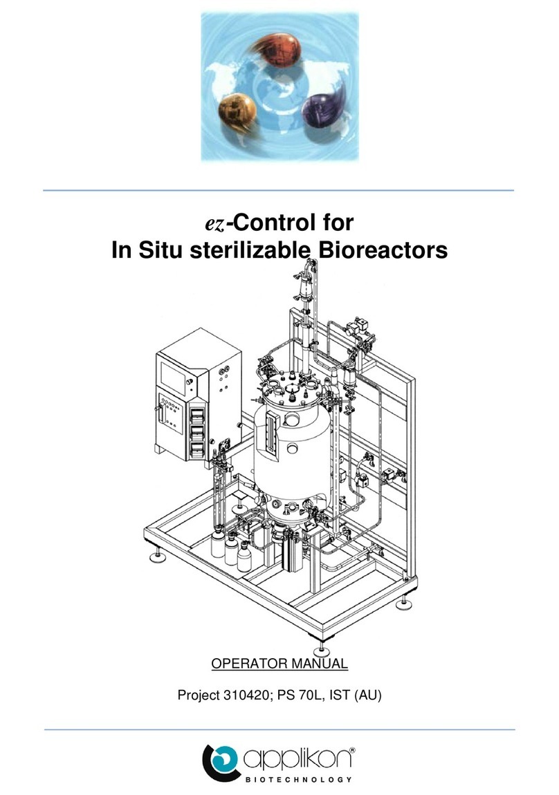
The Applikon range of controlled in situ sterilizable Pilot Systems can be represented by the
following image:
Where: A = the bioreactor,
B = the frame,
C= the ADI 1075
actuator console
containing
temperature and
stirrer control and
with actuators like
pumps and valves,
D = the ADI 1040/21
Control Console
Interface containing
I/O hardware,
E = the Bio Controller
ADI 1010.
The bioreactor system and the
described hardware can be operated as
a stand alone unit.
This hardware manual describes the ADI 1075 Pilot System actuator console with all actuators
that can be incorporated in it.
Also refer to the following manuals:
SHardware & Installation manual of the ADI 1010 Bio Controller,
SFirmware Reference manual,
SOperator manual of the ADI 1010 Bio Controller and ADI 1075 Pilot System,
SHardware manual of the bioreactor,
SPID Control manual.
For information concerning the stirrer speed controller and stirrer motor also refer to the manual
of the applied ADI 1032 stirrer speed controller.

INSTALLATION AND HARDWARE MANUAL
ADI 1075 Pilot System BASIC UNIT
December 2002
2-1
CHAPTER 2
PILOT SYSTEM BASIC UNIT
2.1 INTRODUCTION:
The ADI 1075 Pilot System is an actuator console that is used in combination with In Situ
Sterilizable ADI bioreactors and an ADI 1060 or an ADI 1030 Bio Controller.
It supports gas flow regulation (with rotameters or mass flow controllers), head plate lift
control (optional), stirrer speed control, level control, temperature control (with hot and cold
water or steam) and liquid addition with pumps.
The frame of the Pilot System is available in 2 versions, one for the 20 - 70 l bioreactors and
one for the 100 - 300 l bioreactors.
Caution:
The ADI 1075 Pilot System is designed as an actuator
console for bio process control and must not be used for
other purposes!
On the next pages, the front and side view are presented; also the installation and external
connections are described.

INSTALLATION AND HARDWARE MANUAL
ADI 1075 Pilot System BASIC UNIT
December 2002
2-2
A
BC
D
E
G
H
F
I
2.2 FRONT VIEW:
Front view of the ADI 1075 Pilot System (without frame and wet part)
A = Power section B = Gas supply section
C = Lift control (optional) D = Stirrer speed control
E = Temperature control F = Level control
G = Pump section
H = Connections for pneumatic actuators (wet part)
I = Electric connections

INSTALLATION AND HARDWARE MANUAL
ADI 1075 Pilot System BASIC UNIT
December 2002
2-3
2.3 RIGHT HAND SIDE VIEW:
Right hand side view of the ADI 1075 Pilot System
A = ADI 1075 Pilot System Cabinet B = Frame
C = Wet part D = Connections for Jacket
E = Position for Bioreactor
The ADI 1075 Pilot System Cabinet is mounted on a frame with wheels. The dimension of
the frame depends on the size of the bioreactor (graphical image shows the frame for a 20 -
70 l reactor)
The wet part is used for temperature control purposes (refer to chapter 4) and consists of a
heating element, a circulation pump, pneumatic valves and piping. The dimension of the wet
part depends on the size of the bioreactor (graphical image shows the wet part for a 20 - 70
l reactor). The mounting holes and cable connections at the right hand side are used for
mounting a ADI 1030 or 1060 controller.

INSTALLATION AND HARDWARE MANUAL
ADI 1075 Pilot System BASIC UNIT
December 2002
2-4
A
B
C
DE
F
2.4 REAR VIEW:
Rear view of the ADI 1075 Pilot System
A = Pawl Latches B = Rear Panel
C = Compressed air in/outlet D = Gas inlets (CO2/O2/Air/N2)
E = Mains cable gland F = Wet part connections bulkhead
The rear panel of the ADI 1075 Pilot System can be removed in order to replace fuses (refer
to chapter 2.5: Installation); turn both pawl latches counter clockwise to unlock..
The rear panel is connected internally to the cabinet by an earth wire.
Disconnect this wire before removing the panel.

INSTALLATION AND HARDWARE MANUAL
ADI 1075 Pilot System BASIC UNIT
December 2002
2-5
2.5 INSTALLATION:
PHYSICAL DIMENSIONS:
For physical dimensions (H x W x D) refer to the drawings in chapter 9.
WATER & STEAM SUPPLY:
Supply of water and steam must be connected at the rear of the frame; see pictures below:
Top view of Wet Part for Top view of Wet Part for
20 - 70 L bioreactors 100 - 300 L bioreactors
A = Steam supply A = Steam supply
B = Drain B = Drain
C = Water supply C = Water supply
D = Water return D = Water return
Piping diameter = 12.7mm OD Piping diameter = 21.3mm OD
Note:
- The type of Wet Part connection (hose barb, tri clamp or other) is selected on customer
specification!
- The water return is used for water circulation (or return to drain) during cooling.
- The drain is used to remove water (or condensed steam) during sterilization.

INSTALLATION AND HARDWARE MANUAL
ADI 1075 Pilot System BASIC UNIT
December 2002
2-6
Specifications for water and steam supply:
- Water pressure: 1.5 . . 3.5 barg
- Steam pressure: 2.0 . . 2.5 barg
(Max. Steam temperature = 140 oC)
The required water and steam capacity depend on the reactor size; refer to the hardware
manual of the ADI In Situ Bioreactors.
Apply a (manually operated) ball valve in both the steam and water
supply in order to cut off the water and steam supply during service and
maintenance! The valves must be marked as “steam / water supply
valve for ADI 1075".
COMPRESSED AIR & GAS CONNECTIONS:
The connections (quick connectors) for compressed air and gasses for process control (air,
oxygen, nitrogen and carbon dioxide) are located at the rear (right hand lower corner) of the
ADI 1075 Pilot System cabinet.
Tube diameter (OD) for compressed air: 6 mm,
Tube diameter (OD) for other gasses: 8 mm.
Insert the (poly urethane) tubing (with a little force) into the quick connector until it is fixed.
The tubing can be removed again by pushing the connector inward and pulling the tubing
out.
Required air pressure for actuators: 6 barg,
Required pressure for other gasses: 2 barg for MFC and rotameter applications,
Also refer to chapter 3: Gas supply!
Note:
The bulkhead connector Air Outlet prevents pressure build-up inside the cabinet caused by
air that is released by switching actuators. This bulkhead connector may be used to direct
the air to another area!
Apply a (manually operated) valve in all gas / air supply lines in order to
cut off the gas and air supply during service and maintenance! The
valves must be marked as “air / oxygen / nitrogen / carbon dioxide
supply valve for ADI 1075".

INSTALLATION AND HARDWARE MANUAL
ADI 1075 Pilot System BASIC UNIT
December 2002
2-7
PNEUMATIC & ELECTRIC CONNECTIONS FROM CABINET:
The front of the ADI 1075 Pilot System Cabinet has a number of pneumatic and electric
connections; see picture below:
The pneumatic connections operate the actuators of the Wet Part Valves:
V-2.04 = circulation valve V-2.06 = steam supply to jacket
V-2.07 = water out V-2.08 = circulation valve
V-2.12 = drain (condensate) V-2.13 = steam supply (overall)
V-10.05 = steam to air inlet filter
The electric connections are used to operate the stirrer, circulation pump etc.:
SE-0.01 / M-0.01 = stirrer control (including resolver signal)
IL-1.01 = illumination assembly in reactor head plate
P-2.41 = wet part circulation pump
TS2.02 = thermal cut-off switch
HE-2.71 = heating element

INSTALLATION AND HARDWARE MANUAL
ADI 1075 Pilot System BASIC UNIT
December 2002
2-8
MAINS SUPPLY: 400V3~ or 200V3~ High Voltage Current
The ADI 1075 Pilot System is supplied with a voltage selection package; this package is
available in two voltage versions:
Z310750020 : Pilot System voltage selection package 115 Vac,
Z310750030 : Pilot System voltage selection package 230 Vac.
Verify if the proper voltage selection package was installed (see voltage sticker at the main
supply cable gland); if this is not correct, contact your service office.
CAUTION! ELECTRICAL SHOCK HAZARD!
Connect the main supply cable to the power source according to:
- brown (bn) = L1,
- black1 (bk1) = L2,
- black2 (bk2) = L3,
- blue (bl) = neutral,
- green/yellow (gn/ye) = earth.
Caution:
Minimum specification of the mains cable = 5 x 2.5 mm2. An external mains
supply switch (4 poles, 25 A) must be installed in order to switch off the ADI
1075 Pilot System completely (in case of service).
This external switch must be marked as “disconnecting device for the ADI
1075 Pilot System”.
Using an earth of poor quality may cause malfunctioning of the control
equipment!
Internally each of the three live circuits is used as a separate 115/230 Vac circuit.

INSTALLATION AND HARDWARE MANUAL
ADI 1075 Pilot System BASIC UNIT
December 2002
2-9
Fuses:
Internally - behind the rear panel - a number of fuses can be found. See the image below:
Fuses F21 through F23 are used for the applied stirrer motor and are described in the manual
of the ADI 1032 stirrer speed controller.
The fuses for the internal power supply are described on next page!
Note: All applied fuses must comply with IEC 127!
Fuses F1 through F3 are main fuses for the three separate live circuits,
Fuse F4 = Fuse for “Power-On” circuit,
Fuse F5 = Fuse for “Unswitched Power Supply” (for Control Device),
Fuse F6 = Fuse for “Switched Power Supply” (for Actuator Devices),
Fuse F7 = Fuse for the Lifting Device / Level Sensor Circuit
Fuse F11 = Fuse of Heating Circuit 1 (Temp. Section / Wet part),
Fuse F12 = Fuse of Heating Circuit 2 (Temp. Section / Wet part),
Fuse F13 = Fuse of Heating Circuit 3 (Temp. Section / Wet part),
Fuse F31 = Fuse for “Thermal Cut-off” (Temp. Section / Wet Part),
Specification of fuses F1 through F31 (F21 through F23 are excluded):
F1 . . F3 Ceramic Bus Type 110/120Vac: 20A 230Vac: 10A
F4 5 x 20 mm 110/120Vac: T 1A 230Vac: T 0.5A
F5 5 x 20 mm 110/120Vac: T 2A 230Vac: T 1A
F6 5 x 20 mm 110/120Vac: T 1.6A 230Vac: T 0.8A
F7 (lift control) 5 x 20 mm 230Vac: T 1.6A
F7 (level) 5 x 20 mm 110/120Vac: T 2A 230Vac: T 1A
F11 . . F13 5 x 20 mm 110/120Vac: T 10A 230Vac: T 5A
F31 (24Vdc) 5 x 20 mm T 0.5A
Note:
In case the main supply voltage is 200V3~ (115Vac) and electric head plate lifting is
applied, fuse holder F8 also contains T 1.6A!

INSTALLATION AND HARDWARE MANUAL
ADI 1075 Pilot System BASIC UNIT
December 2002
2-10
The internal power section has its
own fuses (the image shows the
internal power supply board that is
located at the transformer at the
bottom of the ADI 1075 cabinet):
F1 = Main Fuse,
F2 = Fuse circuit 24 Vdc,
F3 = Fuse circuit 12 Vac,
F4 = Fuse circuit 230 Vac.
Fuse type: 5 x 20 mm.
Fuse rating:
F1 = T 5A (110/120 Vac),
T 2.5A (230 Vac),
F2 = T 6.3A,
F3 = T 2A,
F4 = T 1A.
Note:
The 24 Vdc circuit is used for actuator supply and supply for the thermal cut-off of the
heater of the Wet Part.
The 12 Vdc circuit is used for illumination assembly supply (internal illumination of the
Bioreactor).
The 230 Vac circuit is used for circulation pump supply (Wet Part).

INSTALLATION AND HARDWARE MANUAL
ADI 1075 Pilot System BASIC UNIT
December 2002
2-11
2.6 POWER SECTION:
The image of the power section of the ADI 1075 Pilot System is presented below:
Where: A = Power On Indication (green LED),
B = Power On Switch,
C = Emergency Stop Button.
The main power can be switched on by turning the power button 90 degrees clockwise. After
releasing the button it will turn 45 degrees counter-clockwise to a vertical position.
Before switching the main power on, make sure that the wet part and
jacket of the reactor are filled with water! The circulator pump in the wet
part will be damaged when it is operated dry!
If the Emergency Stop button is pressed, all actuators are switched off. The power supply
to the I/O hardware and control device is maintained, so measuring process parameters is
continued. The calculated controller output however is not realized until the Emergency
Stop situation is reset to normal.
Resetting an Emergency Stop situation is done by turning this key clockwise until it returns
to the normal position. After switching the power on again (turn the power on button
clockwise) the normal situation is restored.
Power dips in the Main Power Supply of less than a few seconds will be
overcome automatically (Pilot System will restart automatically). After
a power dip of a longer period, a manual restart is required!
Consequently, when the Emergency Stop situation is reset to normal
within a few seconds, the power supply to the actuators will be
continued immediately (without turning the power on switch clock-wise
manually)!

INSTALLATION AND HARDWARE MANUAL
ADI 1075 Pilot System BASIC UNIT
December 2002
2-12
Note:
After pressing the Emergency Stop button, process control is interrupted since the actuators
are switched off.
In case process control is obtained by use of an ADI 1030, the Emergency Stop situation is
not transmitted to the controller and the calculated values for the controller output will
probably increase to high values.
In order to prevent these increasing controller outputs, the control loops can best be frozen
after pressing the Emergency Stop button. All control loops of the ADI 1030 can be frozen
at once by pressing the FREEZE button on the ADI 1030 keyboard followed by function
key F5 (Freeze All)!
2.7 ENVIRONMENTAL CONDITIONS:
The ADI 1075 Pilot System may be used at locations with the following environmental
conditions:
- Indoor use,
- Altitude: up to 2000 m,
- Temperature: 4oC to 45oC,
- Maximum relative humidity 80% for temperatures up to 31oC, decreasing linearly to 50%
relative humidity at 45oC,
- Mains supply voltage: 115/230 Vac (+15%/-20%), 50/60Hz,
- Transient over voltages according to INSTALLATION CATEGORIES II,
- POLLUTION DEGREE 2 in accordance with IEC 664,
- P-max = 6900 VA.
2.8 CLEANING INSTRUCTIONS:
The ADI 1075 Pilot System (cabinet and frame) may be cleaned with a moist tissue in
combination with a non-abrasive cleaner.

INSTALLATION AND HARDWARE MANUAL
ADI 1075 Pilot System GAS SUPPLY
December 2002
3-1
CHAPTER 3
GAS SUPPLY
3.1 THE GAS SUPPLY UNIT:
The ADI 1075 Gas Supply Unit supports four rotameter assemblies and/or mass flow controllers
for nitrogen, air, oxygen and carbon dioxide:
Inner Mounting Plate
Rotameter Positions
For Mass Flow Controllers
The different gasses are internally connected to a manifold. In this manifold the gasses are
mixed and directed to the gas supply bulkhead connector at the front of the ADI 1075 Pilot
System.
Available rotameter assemblies:
Z3RM000005 Rotameter assembly 2.5 - 25 ml/min,
Z3RM000010 Rotameter assembly 5.0 - 50 ml/min,
Z3RM000020 Rotameter assembly 9.0 - 90 ml/min,
Z3RM000030 Rotameter assembly 27 - 270 ml/min,
Z3RM000040 Rotameter assembly 50 - 500 ml/min,
Z3RM000050 Rotameter assembly 0.1 - 1.0 l/min,
This list is continued on next page!

INSTALLATION AND HARDWARE MANUAL
ADI 1075 Pilot System GAS SUPPLY
December 2002
3-2
A
B
C
D
E
F
Z3RM000060 Rotameter assembly 0.5 - 5.0 l/min,
Z3RM000070 Rotameter assembly 1.0 - 10 l/min,
Z3RM000080 Rotameter assembly 2.3 - 23 l/min,
Z3RM000090 Rotameter assembly 4.3 - 43 l/min,
Z3RM000100 Rotameter assembly 6.0 - 60 l/min.
Rotameter assemblies can be applied with or without a Valve Module:
A = Rotameter
B = Elbow
C = Non return valve
D = Bracket
E = Gas in
F = Gas to reactor
Rotameter Assembly
A + C = Male connector
B = Tubing
D = Solenoid valve
E = Mounting material
G = Gas in
F = Gas to reactor
Rotameter Assembly with Valve Module

INSTALLATION AND HARDWARE MANUAL
ADI 1075 Pilot System GAS SUPPLY
December 2002
3-3
The Valve Modules are available in several versions:
Z311302040 Valve Module for Rotameter Ass., 230 Vac (0 - 23 l/min),
Z311302041 Valve Module for Rotameter Ass., 230 Vac (0 - 60 l/min),
Z311302042 Valve Module for Rotameter Ass., 240 Vac (0 - 23 l/min),
Z311302043 Valve Module for Rotameter Ass., 240 Vac (0 - 60 l/min),
Z311302045 Valve Module for Rotameter Ass., 115 Vac (0 - 23 l/min),
Z311302046 Valve Module for Rotameter Ass., 115 Vac (0 - 60 l/min),
Z311302073 Gas Solenoid Valve 230 Vac (0 - 30 l/min),
Z311302083 Gas Solenoid Valve 115 Vac (0 - 30 l/min).
Note:
- The valve module contains a non-return valve which means that other gasses (or steam) never
can flow back into the supply system!
Mass Flow Controllers are available in the following versions:
Z3MFC0033 Mass Flow Controller Max. 30 l/min 230Vac ADI 1075,
Z3MFC0036 Mass Flow Controller Max. 30 l/min 115Vac ADI 1075,
Z3MFC0100 Mass Flow Controller Max. 100 l/min 230Vac ADI 1075,
Z3MFC0110 Mass Flow Controller Max. 100 l/min 115Vac ADI 1075.
CAUTION:
IF OXYGEN IS ONE OF THE SUPPLIED GASSES, MAKE
SURE THAT THE CONNECTIONS AND TUBING INSIDE THE
ADI 1075 PILOT SYSTEM ARE FREE OF LEAKS!
Note:
- Mass flow controllers are operated by analog output signals of the controller.
- In case mass flow controllers are used without a valve, a non-return valve will be installed
between the MFC and the manifold in order to prevent any back-flow!
Table of contents
Other Applikon Laboratory Equipment manuals