Applikon ez-Control User manual

ez-Control for
In Situ sterilizable Bioreactors
OPERATOR MANUAL
Project 310420; PS 70L, IST (AU)

OPERATOR MANUAL
CONTENTS ez-Control for In Situ sterilizable Bioreactors
Project 310420; PS70 IST (AU)
2
TABLE OF CONTENTS
1GENERAL SAFETY .................................................................................................................................4
1.1 Safety Symbols..................................................................................................................................4
1.2 Safety Warnings ................................................................................................................................5
2GENERAL .................................................................................................................................................7
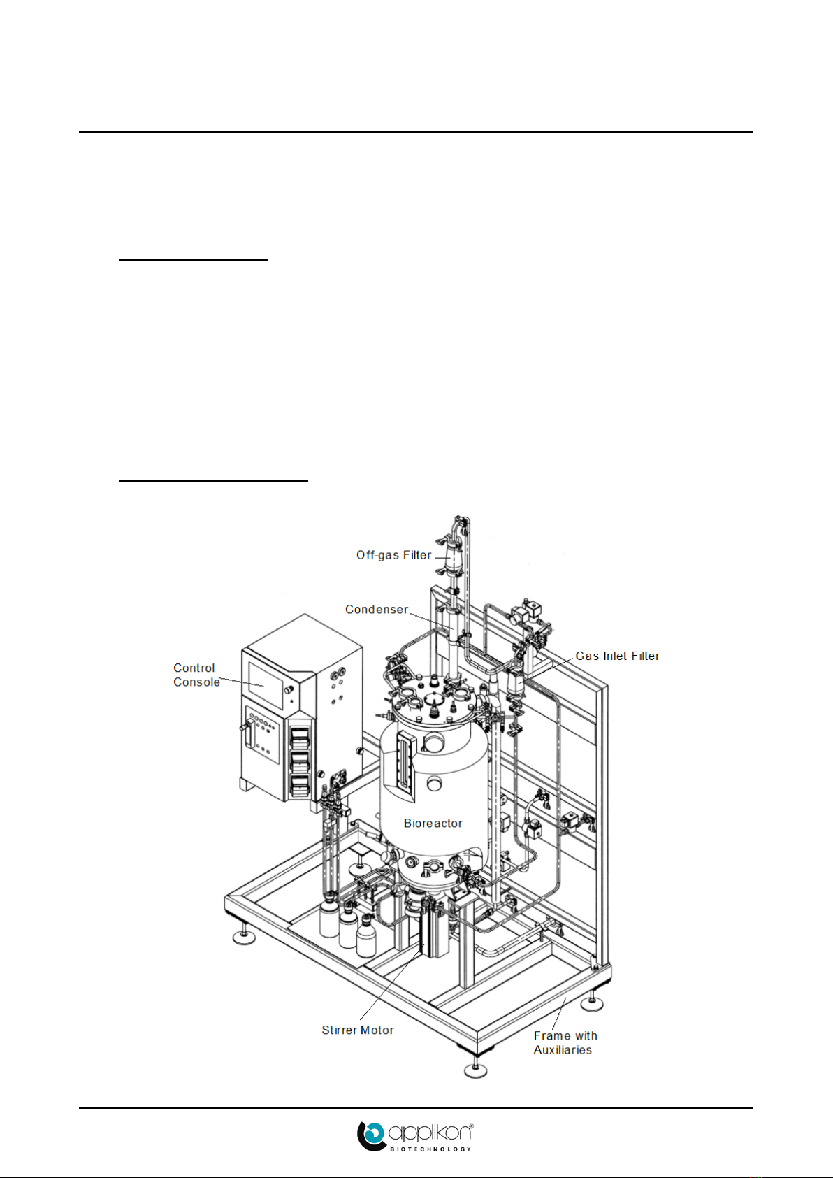
2.1 Introduction.......................................................................................................................................7
2.2 System Overview...............................................................................................................................7
2.3 Home Screen .....................................................................................................................................8
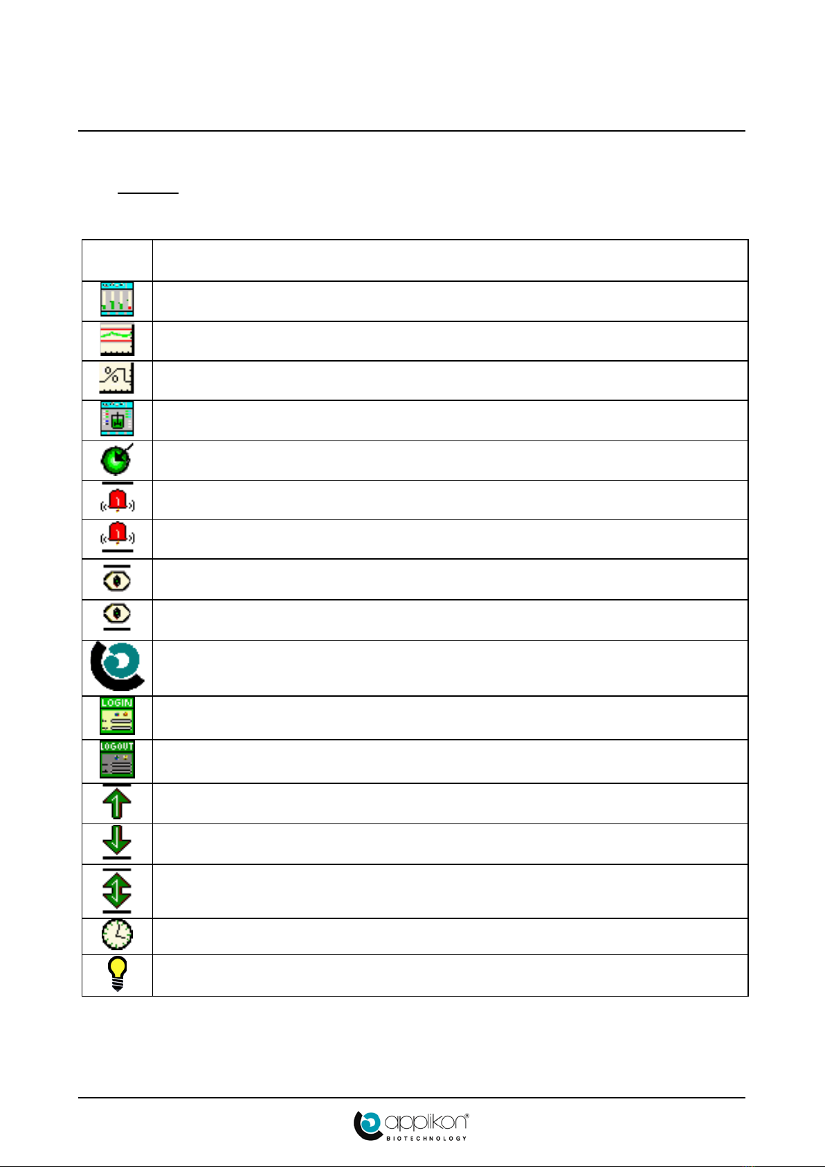
2.4 Icons................................................................................................................................................10
2.5 Keypad and Keyboard.....................................................................................................................11
2.6 Bar Graph and Trend View Screens................................................................................................12
2.7 Set-Points ........................................................................................................................................13
2.8 Configurable Outputs......................................................................................................................14
2.9 Related Manuals..............................................................................................................................14
3GENERAL PREPARATIONS.................................................................................................................15
3.1 General............................................................................................................................................15
3.2 Preparing for a New Process ...........................................................................................................15
3.2.1 Calibrate the pH Sensor.....................................................................................................15
3.2.2 Check the DO Sensor ........................................................................................................16
3.2.3 Other Sensors.....................................................................................................................16
3.2.4 Other Hardware .................................................................................................................16
3.2.5 Prepare Supplies................................................................................................................17
4PRESSURE TEST AND STERILIZATION............................................................................................18
4.1 Pressure Hold Test...........................................................................................................................18
4.2 Sterilization Routine........................................................................................................................18
4.3 Sterilization Settings........................................................................................................................26
4.4 Actuator Activity Matrix .................................................................................................................27
4.5 Execution of the Sterilization Routine.............................................................................................30
4.5.1 Start ...................................................................................................................................30
4.5.2 Initialization.......................................................................................................................30
4.5.3 Pressure Hold Test.............................................................................................................30
4.5.4 Phase 1...............................................................................................................................31
4.5.5 Preheating..........................................................................................................................31
4.5.6 Phase 2...............................................................................................................................31
4.5.7 Sterilization........................................................................................................................32
4.5.8 Natural Cooling .................................................................................................................32
4.5.9 Cooling 2...........................................................................................................................33
4.5.10 Cooling 3...........................................................................................................................33
4.5.11 End ....................................................................................................................................33
5CULTIVATION.......................................................................................................................................34
5.1 Preparing for Cultivation.................................................................................................................34
5.1.1 Prepare the Sensors............................................................................................................34
5.1.2Connect Addition Fluids....................................................................................................36
5.1.3 Activate the Control Loops................................................................................................37
5.2 Start Cultivation by adding Inoculum..............................................................................................38
5.3 Drain Valve.....................................................................................................................................39

OPERATOR MANUAL
ez-Control for In Situ sterilizable Bioreactors CONTENTS
Project 310420; PS70 IST (AU)
3
6CLEANING..............................................................................................................................................40
6.1 Cleaning the sensors........................................................................................................................40
6.2 Cleaning the Bioreactor...................................................................................................................40
6.3 Cleaning Auxiliaries and Tubing.....................................................................................................41
6.4 Maintenance....................................................................................................................................41
7SYSTEM WARNINGS............................................................................................................................42
7.1 Power Failure During Operation .....................................................................................................42
7.2Emergency Stop During Operation .................................................................................................43
© 2015 Applikon-Biotechnology, Delft.
All rights reserved.
This document is protected by copyright law. It may not be reproduced, stored or made public in any form by
any means without the prior written approval of Applikon Biotechnology B.V.

OPERATOR MANUAL
SAFETY ez-Control for In Situ sterilizable Bioreactors
Project 310420; PS70 IST (AU)
4
1GENERAL SAFETY
1.1 SAFETY SYMBOLS
The following symbols are used on the equipment and in this manual.
WARNING
Risk of personal injury or danger to life.
WARNING
Risk of electrical shock hazard.
WARNING
Risk of physical hand injury.
WARNING
Hot surfaces. Take precautions to prevent burns!
Additional information
Applikon Biotechnology B.V. Heertjeslaan 2
2629 JG Delft The Netherlands
Tel.: +31 (0)10-2083555 Fax.: +31 (0)10-2083505
Web: www.applikon-biotechnology.com E-mail: info@applikon-biotechnology.com

OPERATOR MANUAL
ez-Control for In Situ sterilizable Bioreactors SAFETY
Project 310420; PS70 IST (AU)
5
1.2 SAFETY WARNINGS
GENERAL
•This set of equipment has been designed in accordance with EN61010-1 "Safety Requirements for
Electrical Equipment for Measurement, Control and Laboratory Use", and has been supplied in a safe
condition.
•The Hardware manual contains information and warnings, which have to be followed by the user to
ensure safe installation, operation and to retain the equipment in safe condition.
•Before switching on the equipment, make sure that it is set to the line voltage.
•This equipment is designed for bioprocess control; it must not be used for other purposes!
CAUTION
Potential hazard of machinery.
•The stirrer assembly including motor at the bioreactor is a machine with potential hazard (moving parts).
The stirrer motor must not be put into service until the machinery into which it is to be incorporated has
been declared to conform the machinery directive 2006/42/EEC.
WARNING
Risk of electrical shock hazard.
•The cabinet that contains the stirrer speed controller must not be switched on until the motor cable and the
encoder cable are properly connected to both the cabinet and the stirrer motor.
•When the cabinet that contains the stirrer speed controller is switched on, the motor cable and the encoder
cable must not be disconnected. When the motor cable is disconnected, high voltage will be interrupted
(risk of burns and electric shock). When the encoder cable is disconnected, the stirrer speed will increase
in an incontrolled manner since no feed back is available.
CAUTION
Potential hazard of machinery.
•Make sure that the stirrer motor is only operated when it is properly seated in the stirrer assembly of the
bioreactor.
•When the stirrer motor has been put into operation, it will become hot. Take precautions to prevent
personal injury!
WARNING
Risk of physical hand injury caused by pumps.
•In most cases, one or more pumps are installed in the ez-Control.
•According to the European Community legislation on machinery, a pump drive is a machine with
potential hazard. Only apply these drives with the pump heads and tubing that are described in this
manual (chapter: pumps)!
•Switch off the power of the pump drive before replacing any tubes or pump heads.

OPERATOR MANUAL
SAFETY ez-Control for In Situ sterilizable Bioreactors
Project 310420; PS70 IST (AU)
6
CAUTION
Risk of damage to the equipment.
•Do not use the tubing pump drives for other purposes than displacement of fluids (or gas).
•Advised pump tubing (silicone or norprene food) have their limitations in physical and
chemical resistance. Make sure that the pump tubing and the selected reagent type are
compatible. Refer to a Chemical Compatibility Database like:
http://www.coleparmer.com/Chemical-Resistance
•Application of damaged tubes may result in fluid leaking into the pump drive.
•Verify the tube quality inside the pump head before every fermentation run.
Additional information
•Do not apply an Earth Leakage Circuit Breaker in the power supply of the Applikon control equipment
(in an industrial environment or laboratory, an earth leakage circuit breaker is not mandatory).
•Because of the built-in main supply filters, an Earth Leakage Circuit Breaker may be activated. As a
result, the power will be switched off!
•Additional electrical protection can be realized by installing a separation transformer between the mains
and the control equipment.

OPERATOR MANUAL
ez-Control for In Situ sterilizable Bioreactors SAFETY
Project 310420; PS70 IST (AU)
7
2GENERAL
2.1 INTRODUCTION
The Applikon In Situ sterilizable Bioreactor Systems basically consist of the following parts:
•An In Situ sterilizable Bioreactor with the appropriate auxiliaries, like a stirrer assembly, baffles, sensors,
an aeration assembly, etc.
•A wet part for temperature control and steam sterilization.
•An ez-Control with Power Box for measurement and control of process variables (pH, temperature, DO,
level, pressure, and stirrer speed) with corresponding controller outputs in order to keep process
conditions on set-point.
The ez-Control combines and supports actuators like pumps and valves.
2.2 SYSTEM OVERVIEW
Below the combination of the ez-Control and the Pilot System 70L is presented.

OPERATOR MANUAL
GENERAL ez-Control for In Situ sterilizable Bioreactors
Project 310420; PS70 IST (AU)
8
2.3 HOME SCREEN
After switching on the power of the ez-Control, it presents itself (after initialization) on the touch screen
display with its Home Screen.This will be either the Synoptic Screen or the Bar Graph Screen.
The Synoptic Screen shows the actuator activity and measured sensor values (on Process Value buttons).
To view an additional Process parameter (like Pressure for Steam-In-Place applications) in this and other
screens, repeatedly press the Scroll button (which is present in the Synoptic Screen only).
The Bar Graph screen shows Set-points, Alarm Limits, and actual measured values.

OPERATOR MANUAL
ez-Control for In Situ sterilizable Bioreactors GENERAL
Project 310420; PS70 IST (AU)
9
Control loop
The combination of a bar, a Process Value button and a Parameter button represent a single control loop.
Depending on the parameter value and the status of the control loop, the buttons and bars have different
colours.
*) If a control loop has no actuator allocated to it, its deviation alarms will be shown on a red background.
Control buttons
Functional (control) buttons are presented as rectangles
with rounded corners.
Process information
Rectangles with straight corners represent process information
(not a button) or a button without access.
Colours of buttons
Depending on the status of the ez-Control, the specific control loop and the actual screen and on the login
level, the Parameter buttons and other functional (control) buttons have different colours.
Project name
The Project Name / Application Name can be edited after
pressing the top-left button of any screen: the alphanumeric
keyboard that is presented, is discussed in Section 2.5.
At least Operator authorization is required (see Chapter 3).
Colour of Process Value button / Bar Control loop Deviation alarm
Grey Off No alarm
Green On No alarm
Yellow Off *) Alarm
Red On Alarm
Colour of Control / Parameter button Remark
Blue Parameter button or selection button
White The Home button
Brown Option is selected / Device is active
Dark Grey Indicates the path from Home screen to the current
screen
Grey Passive button

OPERATOR MANUAL
GENERAL ez-Control for In Situ sterilizable Bioreactors
Project 310420; PS70 IST (AU)
10
2.4 ICONS
The various buttons and screens show various icons, depending on the actual screen and the control loop
status.
ICON DESCRIPTION
Home: returns to the Home screen (Synoptic or Bar Graph)
Trend: opens the Trend View screen of the corresponding parameter
Trend: opens the percentage-oriented Trend View screen
Synoptic: opens the Synoptic screen
Set-point
High Alarm Limit
Low Alarm Limit
Upper Range Value
Lower Range Value
Applikon logo: enables changing the Project name / Application name
Login (Access Control)
Logout (returns to the View level)
Upper Limit of the Actuator action < 100 %
(default = 100 %)
Low Limit of the Actuator action > 0 %
(default = 0 %)
Low Limit of the Actuator action > 0 %
and
Upper Limit of the Actuator action < 100 %
Actuator has a Timer function with defined On and Off times
Illumination: switches on the lamp in the reactor for a predefined period

OPERATOR MANUAL
ez-Control for In Situ sterilizable Bioreactors GENERAL
Project 310420; PS70 IST (AU)
11
2.5 KEYPAD AND KEYBOARD
The ez-Control presents a numeric keypad when data like Set-points and parameter values must be edited.
Follow the instructions shown above the edit field.
The current value of the parameter is shown in a blue edit field. During editing, this field has a white
background.
The minimum and maximum values for the specific parameter are shown to the right of the edit field.
Notice the current raw value of the parameter as shown near the Cancel button.
Press the ENTER button in order to confirm the new parameter value.
The <=BS button means Back-Space.
The +/-, ., ENTER and EXP buttons are only active when their functions are valid.
The +/-button is a toggle.
For entering texts (like a password), an alphanumeric keyboard is used.
Password recognition in the ez-Control is case-sensitive!

OPERATOR MANUAL
GENERAL ez-Control for In Situ sterilizable Bioreactors
Project 310420; PS70 IST (AU)
12
2.6 BAR GRAPH AND TREND VIEW SCREENS
The Bar Graph screen is an overview of the various parameters of the ez-Control.
Each Set-point value that is shown on a blue Set-point Value button can be edited (see Section 2.7).
The Bar Graph screen gives access to the Parameter Settings screen of a parameter via the corresponding blue
Parameter button (see Chapter 4).
The Process Value button toggles between the Trend View screen(s) of the specific parameter and the Home
screen. Example of a Temperature Trend View screen (press the Temperature Process Value button):

OPERATOR MANUAL
ez-Control for In Situ sterilizable Bioreactors GENERAL
Project 310420; PS70 IST (AU)
13
The Trend View screen shows the following information as a function of time:
•Two red lines represent the alarm limits.
•A black line shows the measured process value.
•A blue line represents the Set-point value (only presented for the time periods when the control loop has
been active).
Only values between the current Range Values will be visible.
In the Trend View screen you can:
•Press on the Lower Range Value or Upper Range Value button, and use the numeric keypad to set a
new view range value.
•Press the Hour Scale button and select a time scale: this time scale applies to all Trend View screens.
•Press the Home button to return to the Home screen.
The alarm limits are defined as part of the control loop settings: press the blue parameter button
and select the Alarm limits option.
The parameter Level has no Trend View screen (therefore, pressing its Process Value button
returns to the Home screen).
The Stirrer parameter has two subsequent Trend View screens: one for the output power (in %)
and one for the stirrer speed (in rpm).
2.7 SET-POINTS
Changing Set-points requires at least Operator authorization (see Chapter 3).
Each Set-point value that is shown on a blue Set-point Value button in the Bar Graph screen or Synoptic
screen can be edited after pressing that button: the numeric keypad will pop up.
The Set-point values can also be changed after pressing the parameter button to display the parameter Setting
screen and then pressing the button Set point.
In case stirrer speed control is configured in a cascade as part of the DO (dissolved oxygen) control loop, the
stirrer speed Set-point will not be shown (example above).

OPERATOR MANUAL
GENERAL ez-Control for In Situ sterilizable Bioreactors
Project 310420; PS70 IST (AU)
14
2.8 CONFIGURABLE OUTPUTS
The default assignment of actuators to control loops can be
edited. This means that the available actuators can be re-
assigned according to specific demands.
The actuators can be renamed to the current assignment.
The lay-out of the parameter status bar can be edited according
to specific demands.
The free assignment of actuators (controller outputs),
renaming actuators and redefining the parameter status bar is
described in section 4.3 (System Configuration) of this
manual!
2.9 RELATED MANUALS
•ez-Control Hardware Manual for In Situ sterilizable Bioreactors,
•ez-Control Operator Manual for In Situ sterilizable Bioreactors,
•ez-Control PID Control Manual for In Situ sterilizable Bioreactors,
•ez-Control Extended I/O Manual.

OPERATOR MANUAL
ez-Control for In Situ sterilizable Bioreactors GENERAL PREPARATIONS
Project 310420; PS70 IST (AU)
15
3GENERAL PREPARATIONS
3.1 GENERAL
Unpacking
•When unpacking the equipment, verify if there is any transport damage and if the reactor is complete (the
way you ordered it).
Cleaning
•Clean all parts with 70% ethanol to remove dust or dirt from shipping.
Assembling
•When assembling the reactor, make sure not to damage the ports, sensors, actuators, or the inside of the
reactor.
3.2 PREPARING FOR A NEW PROCESS
The preparation of the bioreactor for a new cultivation / fermentation process consists of the following steps:
•Check the hardware and its functionality, autoclave contained assemblies separately and mount them in
the reactor;
•Sterilize the reactor, starting with executing a pressure test;
•Prepare for cultivation.
3.2.1 CALIBRATE THE pH SENSOR
Before mounting the sensor in the DN 25 sensor
holder in the reactor, it must be calibrated.
Preparation
1. Connect the pH sensor and the temperature sensor
to the right-hand side of the ez-Control.
2. Start the ez-Control.
3. On the touch screen:
a. Press the pH parameter button.
b. Select the Calibrate pH option.
c. Now press the option 2-point calibration.
It is advised to calibrate on buffer
solutions with pH = 7 and pH = 4
(normal measuring range, stable buffers).
Calibration procedure
1. Place the temperature sensor in the buffer solutions. Enter the temperature of the buffer solutions.
2. Insert the pH sensor in the first buffer solution.
Enter the buffer pH value using the numeric keypad.
After a stability check, the first calibration value is stored.
3. Insert the pH sensor in the second buffer solution.

OPERATOR MANUAL
GENERAL PREPARATIONS ez-Control for In Situ sterilizable Bioreactors
Project 310420; PS70 IST (AU)
16
Enter the buffer pH value using the numeric keypad.
After a stability check, the second calibration value is also stored and the calibration data (slope and
offset) are calculated and stored in the memory of the ez-Control.
For additional information concerning the pH calibration, see the ez-Control Software Reference manual,
section “pH Calibration Routine”.
Mounting the pH sensor
•Insert the gel-filled pH sensor in the sensor holder that fits in a DN 25 port at the lower part of the reactor
wall.
3.2.2 CHECK THE DO SENSOR
Calibration
The DO sensor is calibrated after sterilization is completed and the reactor is cooled down to cultivation
temperature.
If during the previous calibration or cultivation any malfunctioning of the DO sensor was observed, the
membrane module must be replaced. Information about replacing this module can be found in the manual of
this sensor (delivered in the sensor box).
Mounting the DO sensor
1. Mount the DO sensor in a DN 25 port at the lower part of the reactor wall.
3.2.3 OTHER SENSORS
Other sensors, like for temperature, level and pressure, do not need frequent maintenance.
Level sensor
1. Mark the required insertion depth of the level sensor in the head plate with a permanent marker
2. Insert the level sensor completely so that it will be sterilized over the total length
3. After sterilization the level probe can slowly be pulled up until the mark becomes visible (see Section
5.1.1).
3.2.4 OTHER HARDWARE
Push valves, tubing and bottle
The push-valves together with the tubing and filled reagent bottle need to be autoclaved now. For detailed
information, refer to Section 5.1.2.
Other connections to the reactor
Check if all connections are properly fixed. Make sure that all hose clamps are securely tightened.
All ports in head plate and reactor wall must be closed properly by assemblies, sensors or blind stoppers.
Filter elements must be verified and properly fitted.

OPERATOR MANUAL
ez-Control for In Situ sterilizable Bioreactors GENERAL PREPARATIONS
Project 310420; PS70 IST (AU)
17
Rupture disc
If applied, verify that the rupture disc is free of cracks and properly fitted.
Filling the reactor
Fill the reactor with water or medium to working volume (only in case the reactor is sterilized while filled
with liquid).
If the reactor is sterilized empty, there is no need for filling it with liquid.
Empty the gas outlet condenser
Empty the jacket of the gas outlet condenser.
Pump tubing
Application of damaged pump tubes may result in fluid leaking into the pump drive. Verify the tube
quality inside the pump head before each cultivation.
3.2.5 PREPARE SUPPLIES
Verifications
1. Steam supply pressure is minimum 2.0 barg and maximum 2.5 barg.
2. Cooling water is present.
3. Gas supply (compressed air) is available at required pressure (2 barg).
4. Instrument air is present at 6 barg (only if pneumatic membrane valves are applied in the wet part of the
bioreactor).
The reactor system is now prepared for the pressure test and sterilization.

OPERATOR MANUAL
PRESSURE TEST AND STERILIZATION ez-Control for In Situ sterilizable Bioreactors
Project 310420; PS70 IST (AU)
18
4PRESSURE TESTAND STERILIZATION
The pressure hold test and sterilization routine is fully controlled by the Software of the ez-Control (see the
ez-Control Software Reference Manual, section “Menu Options”).
The routine consists of a sequence of discrete steps.
The bioreactor can either be sterilized empty or while it is filled with liquid.
WARNING
Before starting the sterilization routine, make sure that safety measures are taken to prevent
personal injury.
HOT SURFACES
During sterilization of (parts of) the Bioreactor system, the reactor surface, steam supply, wet part,
and drain tubing will be very hot. Take precautions to prevent burns!
4.1 PRESSURE HOLD TEST
One of the first steps of the sterilization routine is a Pressure Hold Test to make sure that the reactor is
airtight. Since the system does not contain a Back Pressure Control Valve, the Pressure Hold Test must
be performed manually!
•Aerate the reactor and close the exhaust valve V-11.02.
•Monitor the pressure gauge at the reactor until the internal pressure reaches 1.3 barg.
•Close aeration valve V-10.19. Wait and monitor the internal reactor pressure.
In case the pressure does not drop more than 0.1 barg in 30 minutes, the Pressure Hold Test is
successfully completed!
In case the pressure drops more than 0.1 barg, the system is not free of leaks. Fix the leak(s) and
perform the test again!
4.2 STERILIZATION ROUTINE
The sterilization of an In-Situ sterilizable bioreactor consists of discrete steps, which are executed in a fixed
order.
In between sterilization steps the operator is prompted to carry out actions with manually operated valves.
The prompts for manual operator actions can be disabled (button Preparation prompts in the Menu –
Sterilization – Configure sterilization screen).
The sterilization routine is based on a specific configuration of manually and automatically operated valves.
Section 4.4 contains a complete overview of the relevant actuator statuses per sterilization / cultivation step.
System Engineers can edit this actuator activity matrix (see ez-Control Software Reference Manual , section
“Sterilization Outputs”).
The schematic diagrams in this section show the major flow schemes for temperature control and aeration
during sterilization and cultivation.

OPERATOR MANUAL
ez-Control for In Situ sterilizable Bioreactors PRESSURE TEST AND STERILIZATION
Project 310420; PS70 IST (AU)
19
Step 1: Start (full or empty) sterilization
At this point in the procedure, the operator needs to confirm that the pH-sensor is calibrated. The
states of the valves and other related actuators are kept as they were during fermentation /
cultivation. When the prompt is confirmed, the Initialization step is started.
Step 2/3: Initialization / Pressure Hold Test
Since no Back Pressure Control Valve is installed, the initialization and automatic Pressure
Hold Test are skipped. The Pressure Hold Test must be performed manually (see section 4.1).
Schematic presentation:
Initialization

OPERATOR MANUAL
PRESSURE TEST AND STERILIZATION ez-Control for In Situ sterilizable Bioreactors
Project 310420; PS70 IST (AU)
20
Step 4: Phase 1
Sterilization is activated: the temperature set-point is set to sterilization temperature (e.g. 123 °C).
Steam valves are opened. Steam is introduced in the reactor jacket. Water (and condensate) from the
jacket of the reactor is drained. The gas inlet filter is not heated with steam yet.
This step is completed when the Preheat temperature is reached.
Since no Back Pressure Control Valve is installed, the sterilization routine cannot be performed
automatically. Throughout the sterilization process (phase 1 . . . sterilization), Off-gas Block valve
V-11.02 must be tuned to such extent that the internal reactor pressure can reach 1.2 . . 1.3 barg!
Phase 1
Other manuals for ez-Control
1
Table of contents
Other Applikon Laboratory Equipment manuals