manuals.online logo
Brands
  1. Home
  2. •
  3. Brands
  4. •
  5. Appsys ProAudio
  6. •
  7. Media Converter
  8. •
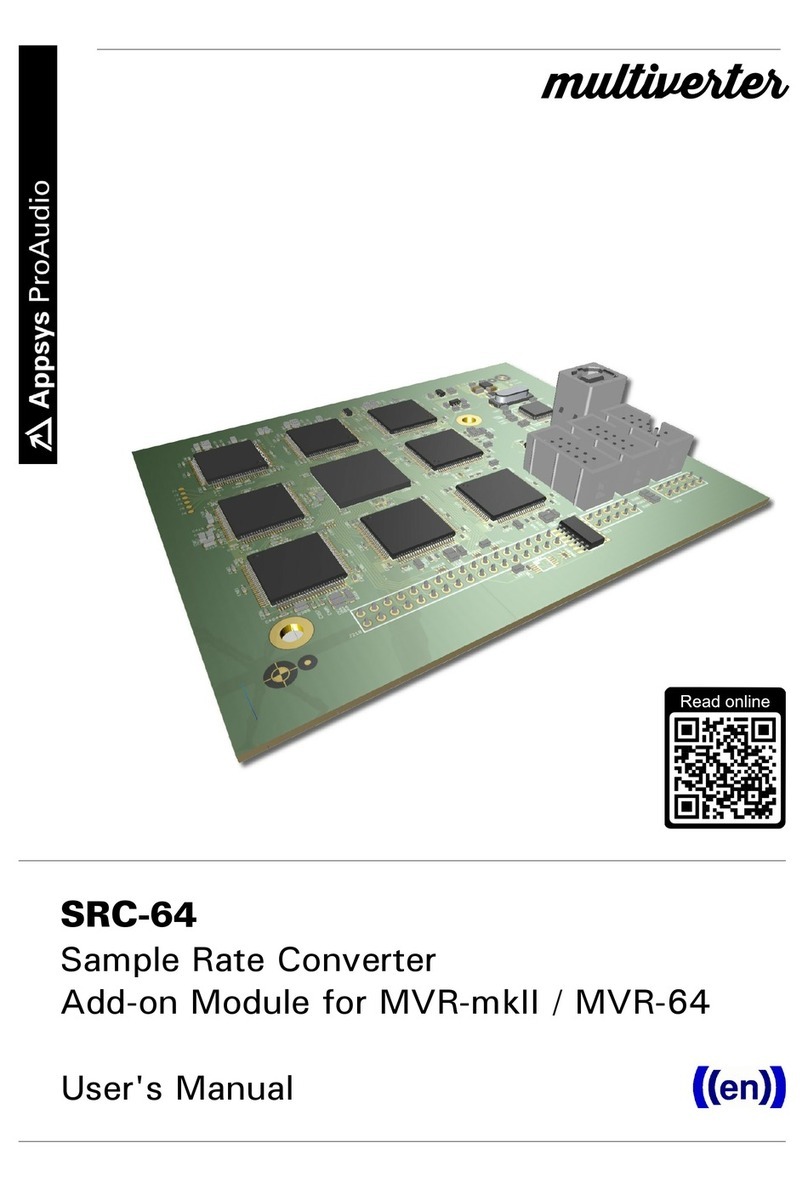
  9. Appsys ProAudio multiverter SRC-64 User manual

Appsys ProAudio multiverter SRC-64 User manual

Other manuals for multiverter SRC-64

1

Other Appsys ProAudio Media Converter manuals

Appsys ProAudio multiverter SRC-64 User manual

Appsys ProAudio

Appsys ProAudio multiverter SRC-64 User manual

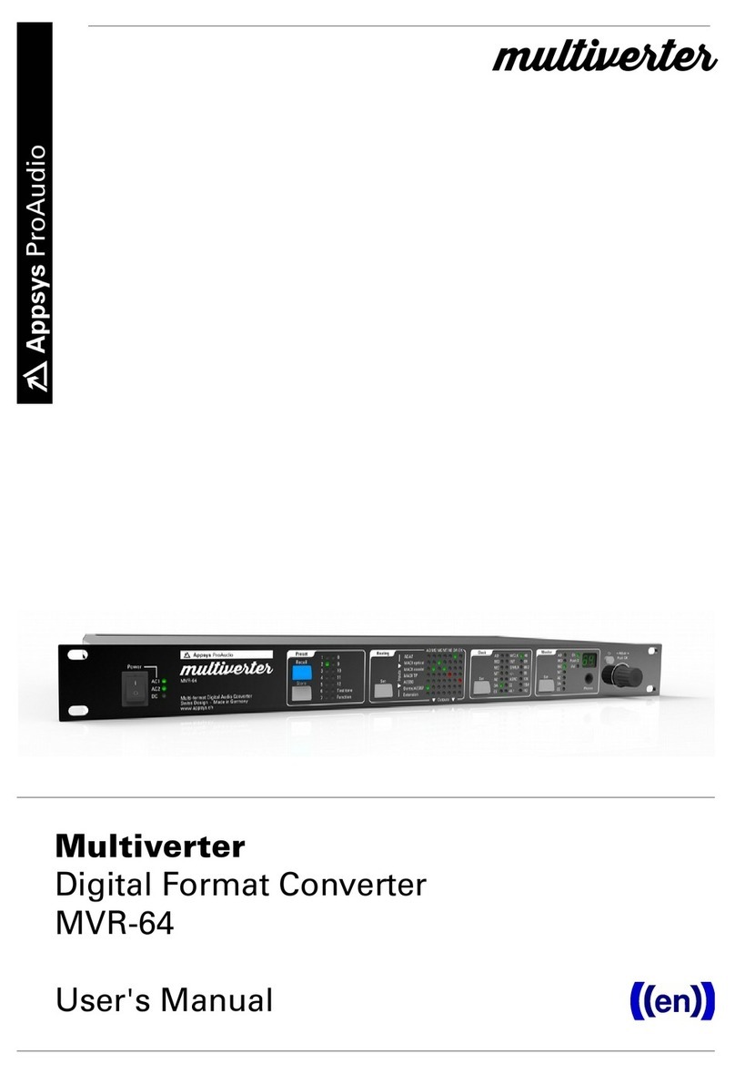
Appsys ProAudio multiverter MVR-64 User manual

Appsys ProAudio

Appsys ProAudio multiverter MVR-64 User manual

Appsys ProAudio Flexiverter AES3 User manual

Appsys ProAudio

Appsys ProAudio Flexiverter AES3 User manual

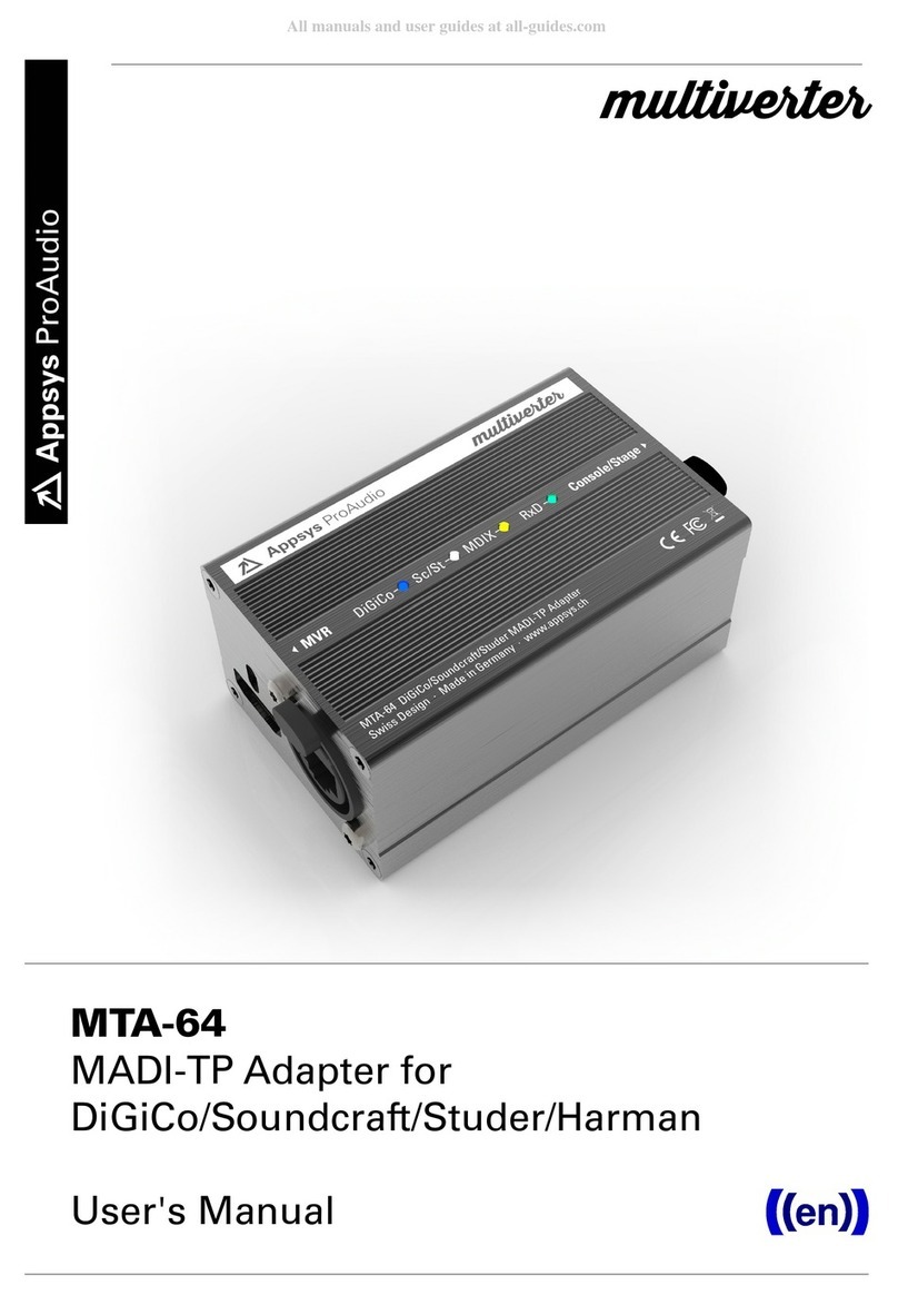
Appsys ProAudio MTA-64 User manual

Appsys ProAudio

Appsys ProAudio MTA-64 User manual

Appsys ProAudio multiverter MVR-64 User manual

Appsys ProAudio

Appsys ProAudio multiverter MVR-64 User manual

Appsys ProAudio Flexiverter MADI User manual

Appsys ProAudio

Appsys ProAudio Flexiverter MADI User manual

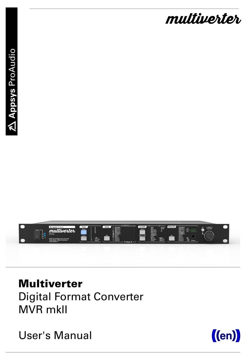
Appsys ProAudio Multiverter MVR mkII User manual

Appsys ProAudio

Appsys ProAudio Multiverter MVR mkII User manual

Popular Media Converter manuals by other brands

TR-Electronic CMS582M-4096/4096 IOL DMS 14H7 KRF Assembly instructions

TR-Electronic

TR-Electronic CMS582M-4096/4096 IOL DMS 14H7 KRF Assembly instructions

Korenix JetCon 2301S user manual

Korenix

Korenix JetCon 2301S user manual

StarTech.com ET91000LCOAM manual

StarTech.com

StarTech.com ET91000LCOAM manual

Alesis AI-3 Reference manual

Alesis

Alesis AI-3 Reference manual

Caton Vpro 5100 user guide

Caton

Caton Vpro 5100 user guide

Cypress CSC-5500 Operation manual

Cypress

Cypress CSC-5500 Operation manual

H&B TX-100 Installation and instruction manual

H&B

H&B TX-100 Installation and instruction manual

Bolin Technology D Series user manual

Bolin Technology

Bolin Technology D Series user manual

IFM Electronic Efector 400 RN30 Series Device manual

IFM Electronic

IFM Electronic Efector 400 RN30 Series Device manual

GRASS VALLEY KUDOSPRO ULC2000 user manual

GRASS VALLEY

GRASS VALLEY KUDOSPRO ULC2000 user manual

Linear Technology DC1523A Demo Manual

Linear Technology

Linear Technology DC1523A Demo Manual

Lika ROTAPULS I28 Series quick start guide

Lika

Lika ROTAPULS I28 Series quick start guide

Weidmuller IE-MC-VL Series Hardware installation guide

Weidmuller

Weidmuller IE-MC-VL Series Hardware installation guide

Optical Systems Design OSD2139 Series Operator's manual

Optical Systems Design

Optical Systems Design OSD2139 Series Operator's manual

Tema Telecomunicazioni AD615/S product manual

Tema Telecomunicazioni

Tema Telecomunicazioni AD615/S product manual

KTI Networks KGC-352 Series installation guide

KTI Networks

KTI Networks KGC-352 Series installation guide

Gira 0588 Series operating instructions

Gira

Gira 0588 Series operating instructions

Lika SFA-5000-FD user guide

Lika

Lika SFA-5000-FD user guide

manuals.online logo
manuals.online logoBrands
  • About & Mission
  • Contact us
  • Privacy Policy
  • Terms and Conditions

Copyright 2025 Manuals.Online. All Rights Reserved.

SRC-64
Asynchronous Sample Rate Converter
Add-on Module for MVR-64
User's Manual
multiverter
User's Manual
Table of Contents
1. ENERAL.....................................................................................................................................3
1.1. Features................................................................................................................................3
1.2. Box Contents........................................................................................................................4
1.3. Conventions used in this manual......................................................................................4
2. INSTALLATION...........................................................................................................................5
2.1. Multiverter Firmware Check...............................................................................................5
2.2. Hardware Installation.........................................................................................................6
3. OPERATION.................................................................................................................................8
3.1. eneral.................................................................................................................................8
3.2. Select the async input........................................................................................................8
3.3. Select the async output......................................................................................................9
3.4. Select the async clock source..........................................................................................10
3.5. ASRC Status Display.........................................................................................................10
4. CONFI URATION EXAMPLES................................................................................................12
4.1. Typical Setups....................................................................................................................12
5. MAINTENANCE........................................................................................................................14
5.1. ASRC selftest......................................................................................................................14
5.2. Determining ASRC Firmware/Hardware version...........................................................14
5.3. ASRC Firmware Upgrade.................................................................................................14
6. SPECIFICATIONS......................................................................................................................16
7. APPENDIX..................................................................................................................................17
7.1. Warranty..............................................................................................................................17
7.2. Manufacturer contact........................................................................................................17
7.3. Recycling............................................................................................................................17
7.4. Document Revision History..............................................................................................17
7.5. About this document.........................................................................................................17
2
SRC-64
1. GENERAL
1.1. Features
The SRC-64 add-on module adds the capability of asynchronous sample rate
conversion to your multiverter. Designed as internal add-on module, it leaves the
"Extension" port available to other break-out boxes.
(Note: The module is called "ASRC" in this manual for clarity).
It features highest analog performance (THD+N -134dB typ.) , 64-channel, bi-
directional conversion between any interfaces supported by the multiverter plus a
number of special modes for maximum flexibility.
The ASRC can be assigned to any input interface and also any output of the
multiverter, giving a true bi-directional conversion between both clock domains:
The ASRC is inserted (by software) between the selected input and the rest of
the multiverter. The input can run independently, and the ASRC takes care of
matching the data to the main clock of the multiverter.
For the output, the ASRC can be inserted between the main clock of the
multiverter and the selected output. The data is then converted to match the
ASRC's asynchronous clock ("async clock") and sample rate before it is sent out.
Existing multiverter routing capabilities are fully preserved.
3
User's Manual
Special modes allow the use of two MADI or AES50 ports together, to send and
receive all 64 channels at 96 kHz (48ch for AES50). Conversions between MADI
64ch@96k => MADI 64ch@48k or vice versa - using two MADI ports for the 96k
part and one for the 48k part - are also supported.
1.2. Box Contents
1 SRC-64 PCB Module
2 Screws M3x20 T10
2 Spacers
This manual
1.3. Conventions used in this anual
A button on the front of the device is shown like this: Set
The encoder can be pushed. This is shown as OK
A particular LED on the front of the device is shown like this: ☼ WCLK
Text indicated on the seven-segment display is shown as 02
A section marked with a warning sign mark tells you that the
information is particularly important to avoid damage or
malfunction.
Filled circles with an exclamation mark indicates an action that
must
be performed (“Required”)
A section marked with a prohibited sign tells you that the action
indicated is prohibited (“Prohibited”)
A section marked with a “information” icon indicates a useful
tip.
4
SRC-64
2. INSTALLATION
2.1. Multiverter Fir ware Check
The multiverter requires at least fir ware 2.0 for the SRC to
work.
Please check and update if required (see below).
Check the multiverter's firmware version: Press Recall , move to
☼ Function , press OK , move to ☼ 12 , press OK , move to ☼ AD
If the seven-segment display shows 02 or higher, your firmware is already
capable of addressing the ASRC, and you can proceed with the next section (2.2
Hardware Installation).
If 01 is shown, a firmware update is required. Download the firmware update
from our website and follow the instructions in the README.TXT file contained
in the package.
5
User's Manual
2.2. Hardware Installation
CAUTION: To prevent electric shock, re ove all ains power
plugs fro the ultiverter before opening!
ATTENTION: Static Sensitive Devices
Observe Precautions for Handling!
Remove the two screws at the rear of the multiverter's top cover
(Torx T10):
Flip the multiverter to detach the top cover. Disconnect the cover's ground
connection at the base.
6
SRC-64
Remove the indicated two screws from the multiverter's main board:
Place the supplied spacers on top of the holes, and carefully plug the ASRC into
the main board.
Insert the supplied screws through the ASRC holes and the spacers, then fasten
them.
Re-connect the cover's ground connection to the base.
Slide the top cover into the front panel slit, then close the lid and mount the
cover using the two black screws.
7
User's Manual
3. OPERATION
3.1. General
The ASRC is configured and enabled/disabled through the "Clock" menu in a few
simple steps, described below.
The general sequence is:
1) Select the async input
2) Select the async output
3) Select the async clock (the clock source for async input+output)
4) Configure the routing matrix (same as without ASRC)
You can always go back to the previous step by pushing the Back⮌ button.
See chapter "4. Configuration Examples" for typical setups.
3.2. Select the async input
This selects the input interface whose data is received at its own asynchronous
clock and sample rate, and is then converted to the multiverter's main clock and
sample rate.
Push the Set button in the "Clock" menu.
Navigate the cursor to the ☼ ASRC LED and push OK to confirm. The seven-
segment display shows1n to indicate the input selection mode.
You can now select the appropriate input row(s). The example shows how to
select "MADI optical" as asynchronous input:
Note: For some configurations it is possible to select two rows at once. This is
used if you want to concatenate the channels from two inputs to make use of all
8
SRC-64
64 channels at 96kHz (48ch with AES50), or 32ch at 192kHz.
When ready, push OK to confirm.
If you need only asynchronous outputs, select "X" for the
inputs.
This disables the receive part of the ASRC, and all inputs run
now on the main clock.
3.3. Select the async output
This selects the output interface whose data is converted from the multiverter's
main clock/sample rate to the async clock on output.
Some interfaces (AES50, Dante/AES67) do not allow dierent
receive and transmit clocks. When such an interface is selected
as input, the output runs automatically at the same clock and
cannot be chosen separately.
Assign the input as described. When this is finished, the seven-segment display
shows 0u to indicate the output selection mode.
Select the appropriate output column(s). The example shows how to select
"MADI optical" as asynchronous output:
Note: For some configurations it is possible to select two rows at once. This is
used if you want to concatenate two outputs together to make use of all 64
channels at 96kHz (48ch with AES50), or 32ch at 192 kHz.
Selecting "X" disables the ASRC for the output direction.
9
User's Manual
If you need only asynchronous inputs, select "X" for the
outputs. Transmitted data is then output at the multiverter's
main clock/sample rate (no samplerate conversion happens for
transmit data).
If no async input and no async output is selected (both "X"),
the ASRC function is disabled and the ASRC is turned o.
3.4. Select the async clock source
This selects the source for the asynchronous clock (the clock which is used for the
selected async inputs and outputs).
Depending on the async interfaces selected, not all interfaces can be used as
source for the async clock. Usually, it's possible to select a) the async input as
clock source, b) the BNC wordclock input, or c) an internally generated clock.
The seven-segment display shows A5 to indicate the "async" clock selection
mode, and the ☼ASRC LED shows yellow.
Navigate the cursor to the desired clock source and push OK to confirm.
Depending on the clock source, the multiverter may ask you now to choose the
SMUX mode (how single-speed data should be interpreted) or the samplerate (if
you are using an internal clock). Push OK to confirm.
3.5. ASRC Status Display
The status LEDs for "Routing", "Clock" and "Monitor" show yellow instead of green
to indicate that the respective function makes use of the ASRC.
When the ASRC is active, the ☼ ASRC LED is lit.
Yellow color indicates that the selected input clock is valid, while red color
indicates that the input clock is missing or invalid.
The ASRC clock source and samplerate are shown in yellow if the clock is valid,
otherwise in red.
In the routing matrix, connections using the ASRC are displayed yellow (in
contrast to the normal green) when the selected conversion involves the use of
the ASRC. If there is any condition which prevents the data from being
converted (i.e. missing input data or clock) the respective connection is shown
in red.
10