Appsys ProAudio multiverter MVR-64 User manual

Multiverter
Digital Format Converter
MVR-64
User's Manual
multiverter

User's Manual
Table of Contents
1. GENERA .....................................................................................................................................4
1.1. Conventions used in this manual.......................................................................................4
1.2. Safety precautions..............................................................................................................5
1.3. Foreword..............................................................................................................................5
1.4. Box Contents........................................................................................................................5
2. INTRODUCTION.........................................................................................................................6
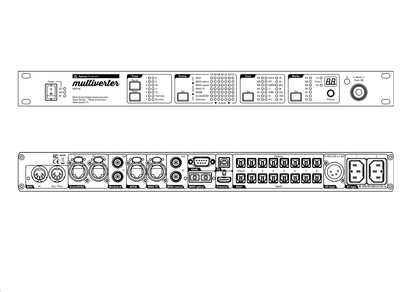
2.1. Front panel...........................................................................................................................6
2.2. Rear panel............................................................................................................................6
2.3. Overview..............................................................................................................................7
2.4. User interface......................................................................................................................7
3. CONNECTIONS OVERVIEW.....................................................................................................12
3.1. AC Power............................................................................................................................12
3.2. DC Power...........................................................................................................................12
3.3. ADAT/SPDIF/AES3 optical................................................................................................12
3.4. PC/USB...............................................................................................................................13
3.5. RS485.................................................................................................................................13
3.6. Extension...........................................................................................................................14
3.7. MADI optical.......................................................................................................................14
3.8. MADI BNC..........................................................................................................................15
3.9. MADI TP.............................................................................................................................15
3.10. AES50...............................................................................................................................15
3.11. Wordclock.........................................................................................................................16
3.12. Dante/AES67....................................................................................................................16
3.13. MIDI..................................................................................................................................17
3.14. Control data forwarding.................................................................................................17
4. PRESETS....................................................................................................................................19
4.1. Preset Recall.......................................................................................................................19
4.2. Preset Store.......................................................................................................................20
4.3. Changed presets...............................................................................................................20
4.4. Auto-Store..........................................................................................................................21
5. ROUTING..................................................................................................................................22
6. C OCKING.................................................................................................................................26
6.1. ClockShield........................................................................................................................26
6.2. Clock source selection......................................................................................................27
6.3. Dante Clock........................................................................................................................29
7. PANE OCK..............................................................................................................................30
8. MONITOR..................................................................................................................................31
9. ADVANCED TOPICS..................................................................................................................33
9.1. Test tone mode..................................................................................................................33
9.2. Configuration settings......................................................................................................33
2

MVR-64
9.3. Audio Interface self-test...................................................................................................37
9.4. ED and button test..........................................................................................................38
9.5. ASRC self-test....................................................................................................................39
10. FIRMWARE..............................................................................................................................40
10.1. Version check....................................................................................................................40
10.2. Upgrade...........................................................................................................................41
11. COMMAND INE REFERENCE...............................................................................................42
12. SPECIFICATIONS....................................................................................................................43
13. ACCESSORIES........................................................................................................................45
13.1. AES50/MADI-TP Pin swap adapter cable......................................................................45
13.2. MTA-64 Adapter for MADI-TP........................................................................................45
13.3. SRC-64 Asynchronous Samplerate Converter Module (optional hardware).............46
13.4. Break-out boxes..............................................................................................................47
14. APPENDIX...............................................................................................................................48
14.1. Warranty...........................................................................................................................48
14.2. Manufacturer contact.....................................................................................................48
14.3. FCC Compliance..............................................................................................................48
14.4. Recycling..........................................................................................................................49
14.5. About this document......................................................................................................49
3

User's Manual
1. GENERAL
1.1. Conventions used in this manual
A button on the front of the device is shown like this: Set
A particular ED on the front of the device is shown like this: ☼ WCLK
Text indicated on the seven-segment display is shown as 02
Operations in a particular control method are indicated by a triangle:
Front panel, Web or Command line
A section marked with a warning sign mark tells you that the
information is particularly important to avoid damage or
malfunction.
Filled circles with an exclamation mark indicates an action
that must be performed (“Required”)
A section marked with a prohibited sign tells you that the
action indicated is prohibited (“Prohibited”)
A section marked with a “information” icon indicates a
useful tip.
4

MVR-64
1. . Safety precautions
This device is intended to be used in a professional
environment with restricted access only.
1.3. Foreword
Thank you for purchasing one of the most innovative digital audio converters on
the market. The multiverter was designed with true vendor independence and
interoperability in mind, with the idea to make all your gear interact seamlessly.
Please note that due to the complex nature of such a product we decided to
introduce functionality step-by-step, so you will find some functions described in
this manual marked “available as firmware update”. We will continue to supply
firmware updates to continuously improve the functionality of the device.
Please don't hesitate to tell us your feedback, thoughts and ideas, we try hard to
make the multiverter your most valuable tool!
1.4. Box Contents
MVR-64 multiverter device
AC power cord (country specific)
This manual
5

. INTRODUCTION
.1. Front panel
. . Rear panel

MVR-64
.3. Overview
The multiverter is a unique device which allows you to convert digital audio data in
any direction between the most popular formats: ADAT, MADI optical, MADI
coaxial, MADI-TP, AES50, Dante and others (via break-out boxes).
All inputs can freely be routed to all of the outputs, with an arbitrary number of
splits and merges supported at the same time.
Channel-wise routing between dierent interfaces is supported via the remote
control via integrated web server, or via command line.
The routing matrix supports 448x448 channels (7x7 interfaces with 64ch each) at
single speed modes, 224x224 channels at double-speed and 112x112 channels at
quad-speed modes.
Using the optional SRC-64 Asynchronous Samplerate Converter Module (optional
hardware), asynchronous sample rate conversion on 64x64 bi-directional channels,
up to 192kHz is supported.
The device is prepared for headamp remote control (Yamaha, Behringer, MIDAS)*.
Diagnostics are made simple by an integrated headphones amplifier and a test
tone generator. Three power inlets allow operation from either AC or DC (battery
pack) with full redundancy.
.4. User interface
The device has been designed for fast and simple operation, with a no-frills
everything-at-a glance concept. The unit can be operated either
directly on the front panel
via the integrated web server
via command line (telnet or USB)
via MIDI (Preset recall only)
In this manual, the required steps for each operation mode are indicated by
Front panel, Web and Command line headers.
All operation modes can be used simultaneously, and any status change is
immediately reflected on all interfaces. For example, it's possible to make some
routing connections on the front panel, and later change them via the web
interface or the command line.
* Not supported in firmware 4.1. Functionality will be supplied later via firmware update
7

User's Manual
Front panel
Most settings are directly accessible without the need to walk through lengthy
menus:
To change a setting, first push the appropriate rectangular button (e.g. Set ).
You have now entered “Menu” mode, indicated by a yellow blinking cursor.
Move the cursor by turning the encoder (rotary knob) left or right to move it to
the desired setting.
When the cursor is at the beginning or end of the column or line, continue
turning to make it wrap around.
Push the encoder knob (or push the appropriate menu button again) to confirm
your changes. To return to the previous state without making any changes, push
the ⮌ Back button.
When the device is normal operation (i.e. not within a menu), turning the
encoder knob changes “Volume” or “Channel” of the monitor headphones,
while pushing the encoder toggles between “Volume” and “Channel” mode.
Channel-wise routing is not available from the front panel due to the lack of
controls.
Web
Thanks to the integrated web server, the multiverter can be remotely operated
from any browser. This is completely self-contained, platform independent and
does not need any additional software.
Web control is the preferred method because it oers channel-
wise routing and provides the most convenient graphical
interface.
The web server runs on the Dante module, and can be configured to run.
(A) on the same network as the Dante audio. This is the normal configuration and
allows to use Dante Audio redundancy.
(B) on a separate network, isolated from the Dante audio. In this case, the
"Primary" port is used for audio, while "Secondary" port is used for remote control.
8

MVR-64
(A) Remote control on the audio network
To access the web control, figure out the symbolic name (as displayed in the
Dante controller, usually MVR-64-xxxxxx (with xxxxxx being some individual
number of the multiverter), and type the following into the browser's address
bar:
http://MVR-64-xxxxxx.local
Alternatively, you can type the IP address of the Dante module (as displayed
in the "Network Config" tab) into the address bar, e.g. 192.168.0.204
Please note that, depending on the network configuration, the module's IP
address can be reassigned by the server.
9

User's Manual
(B) Remote control on a dierent network
In the Dante Controller, under "Network Config", set Dante Redundancy to
"Redundant".
Connect the Audio network to the "Primary" port only and configure it as
desired.
Connect the Control network to the "Secondary" port and configure it as
desired.
10

MVR-64
General remote control considerations
The app uses latest web technologies (HTM 5, AJAX, Server-sent Events etc.)
which require an up-to-date browser. It has been extensively tested with mid-
2018 editions of Chrome, Firefox, Safari and Edge.
Older browsers - including all versions of Internet Explorer - are not supported!
You can run up to four sessions at the same time (i.e. have the page open on
four dierent computers). Any change or status update will propagate within a
few seconds to all connected devices.
Web control has been carefully designed to transfer data only when a change
occurred (and even then only a few bytes) so it generates virtually no additional
load on the Dante network.
Command line
Command line control is available via standard telnet, and also on USB (FT2232
COM port). It provides access to all multiverter functions and routings, and is
perfectly suited for automated tasks.
The telnet server listens on the Dante network, on port 2300. Use a telnet client
to connect to it:
telnet MVR-64-xxxxxx.local 2300
Alternatively, you may use the IP address of the Dante module, either on the
audio network on a separate control network (see Web Control).
When connected via USB, the multiverter shows up as COM port.
Communication can be done with a standard serial terminal (i.e. PuTTY or
minicom). Communication parameters are 115200,8N1.
To obtain a list of all commands, type help at the MVR> command prompt and
press enter.
To exit a command line session, type exit end press enter.
MIDI
The only command understood via MIDI is "Preset Recall".
See 4.1. Preset Recall for details.
Besides this command, the MIDI port may be used to receive and transmit MIDI
data in order to embed/de-embed it to any MADI stream. See 3.14. Control data
forwarding for details.
11

User's Manual
3. CONNECTIONS OVERVIEW
This chapter gives you an overview of all connections on the back of the device.
Please refer to 12. Specifications for full characteristics of each port.
3.1. AC Power
Mains AC inlet, 90-240VAC, 0.75A max.
Together with the DC power port, the inputs are full redundant. If any of the inputs
fail, the other takes immediately over. During the switch-over process, full
operational state is maintained (i.e. no interruptions in the audio flow).
3. . DC Power
Battery / DC inlet, nominal 9-18V, tolerates up to 30V.
Maximum current 2.5A, typical operating current < 1A, standby current ca. 10mA.
Use this port
to operate independently from AC power,
e.g. from a camera battery pack in the field
as battery backup if the AC input(s) fail. To prevent the backup battery from
draining while AC power is present, keep the voltage below 16 volts.
3.3. ADAT/SPDIF/AES3 optical
Eight optical input/output ports are available. Each input and output port can be
run in dierent modes:
ADAT with up to 8 channels per port
SPDIF with up to 2 channels per port
AES3 optical with up to 2 channels per port
For the inputs, the mode is detected automatically. For the outputs, the desired
mode can be set individually via the Web UI on the SETTINGS page (see 9.2
Configuration settings).
12

MVR-64
The ports are mapped to the channels as shown in the table below. Please note
that SPDIF/AES3 channel mapping is not linear, but starts with the same channel
number as ADAT for each port. This allows to keep all routings the same even
when the protocol changes.
Port
Protocol SMUX 1 3 4 5 6 7 8
ADAT x1 1..8 9..16 17..24 25..32 33..40 41..48 49..56 57..64
SPDIF / AES3 x1 1..2 9..10 17..18 25..26 33..34 41..42 49..50 57..58
ADAT x2 1..4 5..8 9..12 13..16 17..20 21..24 25..28 29..32
SPDIF / AES3 x2 1 5 9 13 17 21 25 29
ADAT x4 1..2 3..4 5..6 7..8 9..10 11..12 13..14 15..16
SPDIF / AES3 x4 not supported
Table 1: Optical port channel mapping
When ADAT, SPDIF or AES3 is used as clock source, Port 1 must be connected and
is used as master clock.
3.4. PC/USB
The USB port is used for firmware update, and as Remote Control Port for the PC
(serial terminal, 115200, 8N1. See Command line on p.11 for details).
The USB port does NOT carry audio data!
To interface the audio system of the multiverter to a computer,
connect is using Ethernet to the Dante port and use the Dante
Virtual Soundcard software.
3.5. RS485
The RS485 port is prepared to send and receive Yamaha Headamp Remote control
information*.
* Not implemented in firmware 4.1. Functionality will be supplied later via firmware update
13

User's Manual
3.6. Extension
This port is designed to connect break-out boxes to support other, non-built-in
protocols and standards (e.g. AVB), or to connect additional ports for system
extension.
Currently supported (as of 2019-08):
Product Purpose
MTA-64 Adapter for DiGiCo/Soundcraft/Studer/Harman MADI-TP variant
Note: The MTA-64 uses the Extension port only for power, not for audio. The port
is fed through on the MTA-64 and remains available for other extension boxes.
Please contact us for the scheduled availability of other break-out boxes.
Two multiverters can be connected together via the extension
port when a larger number of dierent ports is required.
Note: Although this port makes use of a standard HDMI connector, it is NOT
compatible with HDMI devices. Don't connect HDMI equipment! The HDMI
connector was chosen because cables are ubiquitous and can easily be replaced
(and also because the electrical characteristics are perfectly suited for this
purpose).
3.7. MADI optical
This port carries MADI data, according to the “optical” transmission method
specified in AES10.
The yellow ED indicates the current status:
O: No incoming MADI data detected
On: Incoming MADI detected, but no valid system clock
Flashing: Incoming MADI and valid system clock detected
Control data (e.g. for preamp control) can be forwarded over this port. See 3.14,
Control data forwarding for details.
Where possible, use the "MADI optical" connection
rather than BNC or TP connections to reduce the chances
of noise/interference and to increase reach.
14

MVR-64
3.8. MADI BNC
This port carries MADI data according to the “coaxial” transmission method
specified in AES10.
The yellow ED indicates the current status:
O: No incoming MADI data detected
On: Incoming MADI detected, but no valid system clock
Flashing: Incoming MADI and valid system clock detected
Control data (e.g. for preamp control) can be forwarded over this port. See 3.14,
Control data forwarding for details.
3.9. MADI TP
This port carries MADI data, according to the “MADI over Twisted Pair cabling”
method specified in the draft for the upcoming AES10 standard (AES-X-213).
To interface to the DiGiCo or Soundcraft/Studer/Harman
variants of MADI-TP, an external MTA-64 adapter is required.
See
The EDs indicates the current status:
Yellow: ink detected
Green: Input data valid and system clock valid
This port can also be used as second AES50 port (adapter cable and altered setting
required – see 9.2 Configuration settings, and 13.1 AES50/MADI-TP Pin swap
adapter cable). This second port may be used either as standalone port (48ch) or in
channel aggregation mode, meaning that both AES50 ports are treated as one
single interface with the first port carrying channels 1-48/1-32 (1-24/1-16@96kHz)
and the second port carries channels 49-64/33-64(25-32/17-32@96kHz).
Control data (e.g. for preamp control) can be forwarded over this port. See 3.14,
Control data forwarding for details.
3.10. AES50
This port carries Behringer/MIDAS compatible digital audio data (48ch@ 48kHz,
24ch@96kHz). It is also prepared to transmit control data from and to
15

User's Manual
Behringer/MIDAS preamps (i.e. for remote gain control).*
The EDs indicates the current status:
Yellow: ink detected
Green: Input data valid and system clock valid
To use more than 48/24 channels with AES50, the MADI-TP
port can be configured to work as second AES50 port.
Use the channel-wise routing feature from the Web remote
to map the channels as required.
This port can also be switched to work as second MADI-TP port (see 9.2
Configuration settings, and 13.1 AES50/MADI-TP Pin swap adapter cable). In MADI-
TP mode, Control data (e.g. for preamp control) can be forwarded over this port.
See 3.14, Control data forwarding for details.
3.11. Wordclock
The wordclock input accepts a square wave signal in the frequency of the sample
rate. x2 and x4 modes are automatically detected when the square wave has x2/x4
frequency, and can be manually set when the square wave has x1 frequency.
A 75 ohms termination resistor can internally be switched but is OFF by default.
Altering the setting requires opening of the device, please contact us for further
information.
The wordclock output is a square wave signal (50% duty cycle) and is able to drive
up to two 75 ohm resistors in parallel. Its frequency is either identical to the
sample rate or always x1 (see 9.2 Configuration settings).
3.1 . Dante/AES67
The “Primary” and “Secondary” ports are standard gigabit Ethernet ports,
designed to connect to Dante Digital Audio Network. AES67 mode is alternative to
Dante mode and can be set in the Dante Controller Software.
* Not implemented in firmware 4.1. Functionality will be supplied later via firmware update.
16

MVR-64
The Dante port provides also the Web UI and a telnet server
(on port 2300) for remote control. Both services are available
on the same IP address as the Dante audio interface (use the
Dante Controller software to determine or change the IP).
The port EDs indicates the current status:
Yellow: ink detected
Green: Input data valid and system clock valid
Please refer to the Audinate website for information about Dante Technology, the
latest Dante Controller drivers and related information.
By default, the ports are configured to act as switch (which allows daisy
chaining), but can be changed using the Dante Controller Software as redundant
ports for parallel connection.
3.13. MIDI
The only command supported via the MIDI port is "Preset Recall".
See 4.1 Preset Recall.
The yellow ED near the port flashes when incoming MIDI data is detected. All
incoming data is forwarded to the MIDI THRU port, to allow daisy-chaining of
devices.
Control data (e.g. for preamp control) can be forwarded over this port. See 3.14,
Control data forwarding for details.
3.14. Control data forwarding
The multiverter is able to forward control data (headamp/stagebox control)
between MADI ports, and from and to the MIDI ports. The multiverter provides
transparent forwarding of all extra AES3 bits (V)alid, (U)ser data and (C)hannel
status, which makes it compatible to all vendor-specific remoting protocols.
To enable remoting, the channels containing the control data must be routed 1:1
(i.e. linearly), depending on the vendor protocol.
17

User's Manual
Vendor Control method
DiGiCo Control data is contained in all bits (audio+user) of channel 57.
To enable forwarding between dierent MADI ports,
•Set MADI transmit mode of the involved MADI ports to 57ch
(see 9.2 Configuration settings)
•Route ch 57 to ch 57 both ways
Soundcraft Control data is contained in the "U" bit of channels 1..10.
•To enable forwarding between dierent MADI ports, route ch 1..10 to
ch 1..10 both ways
RME, FerroFish,
DirectOut
(MIDI over MADI)
Control data is contained in the "U" bit of channel 56 (ch28 in 96k mode)
•To enable forwarding between dierent MADI ports, route ch 56 to ch
56 both ways.
•To enable forwarding from/to the MIDI ports on the rear to/from a
particular MADI port, set "[08] MIDI forwarding" to the desired MADI
port (see 9.2 Configuration settings)
Table 2: Remote control over MADI
18

MVR-64
4. PRESETS
All settings (excluding headphones level) can be individually stored in one of the
12 preset locations, and may be recalled at any time later. The settings are stored
in non-volatile memory and are retained for years even if the device is switched o
or the power cable is unplugged. Additionally, the settings can be downloaded via
the Web UI, and restored on the same or a dierent device.
4.1. Preset Recall
Front panel
To recall a preset:
Push the Recall button from the “Preset” menu.
Select the desired storage location ☼ 1 to ☼ 12 by turning the encoder left or
right.
Note: The presets “Test tone” and “Function” have special purposes.
See 9. Advanced Topics.
Confirm the selected location by pushing the encoder, or push the
⮌ Back button to cancel the operation.
Web
From the "PRESET " menu, choose the desired preset number. An asterisk next
to the number indicates that modifications to the recalled preset have been done.
To save the modifications, choose "PRESET / Store".
Note: You can also upload presets from a file to the MVR. This is useful when
transferring setups between dierent multiverters.
Command line
preset recall <n m>
MIDI
Preset recall is done via "Program Change" messages
(program 00 = Preset 1 ... program 11 = Preset 12).
The MIDI channel is set to 1 by default but can be altered using function "07".
(Note: The channel is a per-preset setting, if you need to change it you will need to
do so in all 12 presets).
19

User's Manual
4. . Preset Store
Front panel
To store a preset:
Push the Store button in the “Preset” menu.
Select the desired storage location ☼ 1 to ☼ 12 by turning the encoder left or
right.
Confirm the selected location by pushing the encoder, or push the
⮌ Back button to cancel the operation.
Web
Select "PRESET / Store" menu to store the preset as current preset number, or
select "PRESET / Store as..." to choose a dierent number.
Note: You can also download presets to a file. This is useful when transferring
setups between dierent multiverters.
Command line
preset store [<n m>]
4.3. Changed presets
Front panel
When a preset is recalled, the corresponding location ☼ 1 to ☼ 12 is lit green.
If any setting is changed afterwards (except for headphones level), the ED turns
red to indicate that the current setting diers from the recalled preset. If you want
your changes to be reflected also in the stored preset, just store the preset again.
Otherwise, the changes are overwritten
the next time a preset is recalled.
Web
A changed preset is indicated by an asterisk (*) next to the preset number.
Use "PRESET / Store" to permanently store changes into that preset.
Command line
A changed preset is indicated by an asterisk (*) next to the preset number.
The current preset can be queried by calling preset without parameters.
20
Other manuals for multiverter MVR-64
1
Table of contents
Other Appsys ProAudio Media Converter manuals

Appsys ProAudio
Appsys ProAudio Flexiverter MADI User manual

Appsys ProAudio
Appsys ProAudio multiverter SRC-64 User manual

Appsys ProAudio
Appsys ProAudio multiverter SRC-64 User manual

Appsys ProAudio
Appsys ProAudio MTA-64 User manual

Appsys ProAudio
Appsys ProAudio multiverter MVR-64 User manual

Appsys ProAudio
Appsys ProAudio Flexiverter AES3 User manual

Appsys ProAudio
Appsys ProAudio Multiverter MVR mkII User manual