Appsys ProAudio multiverter MVR-64 User manual

multiverter
Multiverter
Digital Format Converter
MVR-64
User's Manual

User's Manual
Table of Contents
1. GENERAL.....................................................................................................................................4
1.1. Foreword...............................................................................................................................4
1.2. Box Contents........................................................................................................................4
1.3. Convent ons used n th s manual.......................................................................................5
2. INTRODUCTION..........................................................................................................................6
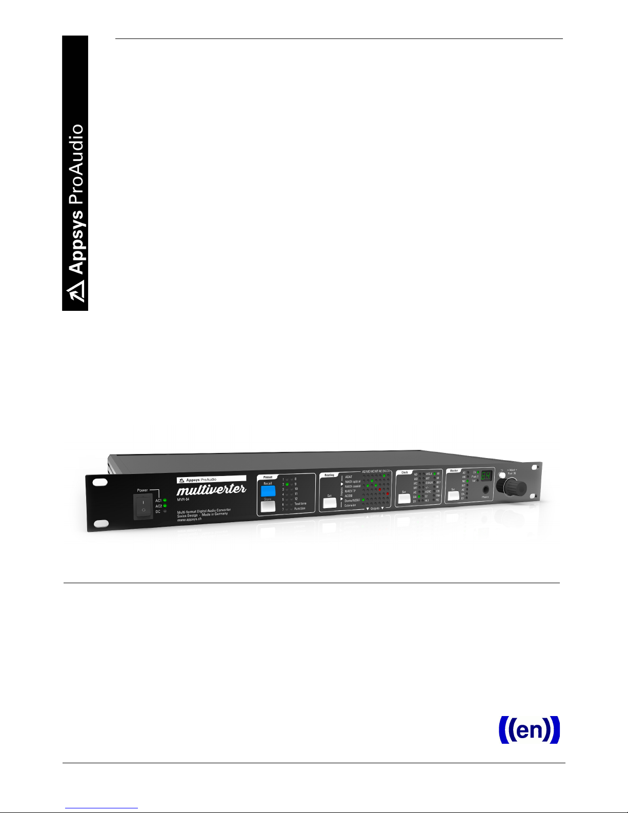
2.1. Front panel............................................................................................................................6
2.2. Rear panel.............................................................................................................................6
2.3. Overv ew...............................................................................................................................7
2.4. Operat ng Pr nc ples............................................................................................................7
3. CONNECTIONS OVERVIEW.......................................................................................................9
3.1. AC Power..............................................................................................................................9
3.2. DC Power..............................................................................................................................9
3.3. ADAT.....................................................................................................................................9
3.4. PC/USB..................................................................................................................................9
3.5. RS485..................................................................................................................................10
3.6. Extens on............................................................................................................................10
3.7. MADI opt cal.......................................................................................................................10
3.8. MADI BNC...........................................................................................................................11
3.9. MADI TP..............................................................................................................................11
3.10. AES50................................................................................................................................12
3.11. Wordclock.........................................................................................................................12
3.12. Dante/AES67.....................................................................................................................13
3.13. MIDI...................................................................................................................................13
4. PRESETS....................................................................................................................................14
4.1. Recall...................................................................................................................................14
4.2. Store....................................................................................................................................14
4.3. Changed presets................................................................................................................14
4.4. Auto-Store..........................................................................................................................14
5. ROUTING...................................................................................................................................15
6. CLOCK SOURCE........................................................................................................................16
6.1. Dante Clock.........................................................................................................................16
7. MONITOR...................................................................................................................................18
8. ADVANCED TOPICS..................................................................................................................19
8.1. Test tone mode..................................................................................................................19
8.2. Parameter sett ngs.............................................................................................................19
8.3. Mult verter Remote Control..............................................................................................21
8.4. Headamp Remote Control................................................................................................21
8.5. F rmware Upgrade.............................................................................................................21
9. SPECIFICATIONS.......................................................................................................................23
10. ACCESSORIES.........................................................................................................................25
2

MVR-64
10.1. AES50/MADI-TP P n swap adapter cable.......................................................................25
10.2. Asynchronous Sample Rate Converter (ASRC) module..............................................25
10.3. Break-out boxes...............................................................................................................25
11. APPENDIX................................................................................................................................26
11.1. Warranty...........................................................................................................................26
11.2. Manufacturer contact......................................................................................................26
11.3. Recycl ng...........................................................................................................................26
11.4. About th s document.......................................................................................................26
3

User's Manual
1. GENERAL
1.1. Foreword
Thank you for purchas ng one of the most nnovat ve d g tal aud o
converters on the market. The mult verter was des gned w th true vendor
ndependence and nteroperab l ty n m nd, w th the dea to make all your
gear nteract seamlessly.
Please note that due to the complex nature of such a product we dec ded
to ntroduce funct onal ty step-by-step, so you w ll f nd some funct ons
descr bed n th s manual marked “ava lable as f rmware update”. We w ll
cont nue to supply f rmware updates to cont nuously mprove the
funct onal ty of the dev ce.
Please don't hes tate to tell us your feedback, thoughts and deas, we try
hard to make the mult verter your most valuable tool!
1.2. Box Contents
MVR-64 mult verter dev ce
One AC power cable (country spec f c)
Th s manual
4

MVR-64
1.3. Convent ons used n th s manual
A button on the front of the dev ce s shown l ke th s: Set
A part cular LED on the front of the dev ce s shown l ke th s: ☼ WCLK
A sect on marked w th an warn ng s gn mark tells you that the
nformat on s part cularly mportant to avo d damage or malfunct on.
F lled c rcles w th an exclamat on mark nd cates an act on that must be
performed (“Requ red”)
A sect on marked w th a proh b ted s gn tells you that the act on nd cated
s proh b ted (“Proh b ted”)
A sect on marked w th a “ nformat on” con nd cates a useful t p.
5

2. INTRODUCTION
2.1. Front panel
2.2. Rear panel

MVR-64
2.3. Overv ew
The mult verter s a un que dev ce wh ch allows you to convert d g tal
aud o data between the most popular formats (ADAT, MADI opt cal, MADI
coax al, MADI-TP, AES50, and Dante - plus other formats v a break-out
boxes). All nputs can freely be routed to all of the outputs n a “matr x”
fash on: When a connect on n the matr x s made, all nput channels are
1:1 routed to the output nterface.1 Even mult ple s multaneous
convers ons are poss ble, w th a super low latency down to 3 samples
( nterface dependent).
Up to 64 channels per convers on are supported at s ngle speed (x1)
modes (32/44.1/48kHz), up to 32 channels at double-speed (x2) modes
(64/88.2/96kHz) and up to 16 channels at quad-speed (x4) modes
(128/176.4/192kHz).
The dev ce s prepared for headamp remote control (Yamaha, Behr nger,
MIDAS) and can even convert between the d fferent vendor-spec f c
control formats to allow true system nteroperab l ty*.
D agnost cs are made s mple by an ntegrated headphones ampl f er and a
test tone generator. Three power nlets allow operat on from e ther AC or
DC (battery pack) w th full redundancy.
2.4. Operat ng Pr nc ples
The dev ce has been des gned for fast and s mple operat on, w th a no-
fr lls everyth ng-at-a glance concept. Most sett ngs are d rectly access ble
w thout the need to walk through lengthy menus:
To change a sett ng, f rst push the appropr ate rectangular button (e.g.
Set ). You have now entered “Menu” mode, nd cated by a yellow
bl nk ng cursor.
Move the cursor by turn ng the encoder (rotary knob) left or r ght to
move t to the des red sett ng.
Push the encoder knob (or push the appropr ate menu button aga n) to
conf rm your changes. To return to the prev ous state w thout mak ng
any changes, push the ⮌ Back button.
When the dev ce s normal operat on ( .e. not w th n a menu), turn ng
the encoder knob changes “Volume” or “Channel” of the mon tor
headphones, wh le push ng the encoder toggles between “Volume”
and “Channel” mode.
1 Channel-w se rout ng (comb n ng channels from d fferent nterfaces nto one output) s currently
unsupported. Please contact us for poss ble solut ons.
* Not supported n f rmware package 1.0.0, w ll be suppl ed as update
7

User's Manual
3. CONNECTIONS OVERVIEW
Th s chapter g ves you an overv ew of all connect ons on the back of the
dev ce. Please refer to 9. Spec f cat ons for full character st cs of each port.
3.1. AC Power
Ma ns AC nlet, 90-240VAC, 0.75A max.
Together w th the DC power port, the nputs are full redundant. If any of
the nputs fa l, the other takes mmed ately over. Dur ng the sw tchover
process, full operat onal state s ma nta ned ( .e. no nterrupt ons n the
aud o flow).
3.2. DC Power
Battery / DC nlet, nom nal 9-18V, tolerates up to 30V.
Max mum current 2.5A, typ cal operat ng current < 1A, standby current ca.
10mA.
Use th s port
to operate ndependently from AC power, e.g. from a camera battery
pack n the f eld
as battery backup f the AC nput(s) fa l. To prevent the backup battery
from dra n ng wh le AC power s present, keep the voltage below 16
volts.
3.3. ADAT
E ght ADAT nput/output ports w th 8 channels each (4 channels n SMUX
mode). The ports are mapped to the channels as follows:
Port 1 2 3 4 5 6 7 8
Channels 1-8 9-16 17-24 25-32 33-40 41-48 49-56 57-64
Channels
(SMUX)
1-4 5-8 9-12 13-16 17-20 21-24 25-28 29-32
If ADAT s used as Clock Source, Input port 1 must be connected, and s
used as master clock.
3.4. PC/USB
The USB port s used for f rmware update, and as Remote Control Port for
the PC n the future. It s NOT capable of pass ng aud o data!
8

MVR-64
To nterface the aud o system of the mult verter to a computer, connect
s us ng Ethernet to the Dante port and use the Dante V rtual Soundcard
software.
3.5. RS485
The RS485 port s prepared to send and rece ve Yamaha Headamp
Remote control nformat on*.
3.6. Extens on
Th s port s des gned to connect break-out boxes to support other, non-
bu lt- n protocols and standards (e.g. AVB), or to connect add t onal ports
for system extens on.
Please contact us for the scheduled ava lab l ty of break-out boxes.
Two mult verters can be connected together v a the extens on port when
a larger number of d fferent ports s requ red.
Note: Although th s port makes use of a standard HDMI connector, t s
NOT compat ble w th HDMI dev ces. Don't connect HDMI equ pment
there! The HDMI connector was chosen because cables are ub qu tous
and can eas ly be replaced (and also because the electr cal character st cs
are perfectly su ted for th s purpose).
3.7. MADI opt cal
Th s port carr es MADI data, accord ng to the “opt cal” transm ss on
method spec f ed n AES10.
The yellow LED nd cates the current status:
Off: No ncom ng MADI data detected
On: Incom ng MADI detected, but no val d system clock
Flash ng: Incom ng MADI and val d system clock detected
The port s prepared to handle also MIDI control data (MIDI over MADI)
* Not mplemented n f rmware package 1.0.0. Funct onal ty w ll be suppl ed later v a f rmware update
9

User's Manual
compat ble to RME gear*.
Where poss ble, use the "MADI opt cal" connectect on rather than BNC or
TP connect ons to reduce the chances of no se/ nterference and to
ncrease reach.
3.8. MADI BNC
Th s port carr es MADI data accord ng to the “coax al” transm ss on
method spec f ed n AES10.
The yellow LED nd cates the current status:
Off: No ncom ng MADI data detected
On: Incom ng MADI detected, but no val d system clock
Flash ng: Incom ng MADI and val d system clock detected
The port s prepared to handle also MIDI control data (MIDI over MADI)
compat ble to RME gear*.
3.9. MADI TP
Th s port carr es MADI data, accord ng to the “MADI over Tw sted Pa r
cabl ng” method spec f ed n the draft for the upcom ng AES10 standard
(AES-X-213).
NOTE: Several propr etary mplementat ons of “MADI over Tw sted Pa r”
ex st pr or to standard zat on. Most of them are ncompat ble to the
method spec f ed n AES-X-213.
The LEDs nd cates the current status:
Yellow: L nk detected
Green: Input data val d and system clock val d
Th s port can also be used as second AES50 port (adapter cable and
altered sett ng requ red – see 8.2 Parameter sett ngs, and 10.1
AES50/MADI-TP P n swap adapter cable). Th s second port may be used
e ther as standalone port (48ch) or n channel aggregat on mode, mean ng
that both AES50 ports are treated as one s ngle nterface w th the f rst port
* Not mplemented n f rmware package 1.0.0. Funct onal ty w ll be suppl ed later v a f rmware update
10

MVR-64
carry ng channels 1-48 (1-24@96kHz) and the second port carr es channels
49-64 (25-32@96kHz).*
3.10. AES50
Th s port carr es Behr nger/MIDAS compat ble d g tal aud o data (48ch@
48kHz, 24ch@96kHz). It s also prepared to transm t control data from and
to Behr nger/MIDAS preamps ( .e. for remote ga n control).*
The LEDs nd cates the current status:
Yellow: L nk detected
Green: Input data val d and system clock val d
To use more than 48/24 channels w th AES50, the MADI-TP port can be
conf gured to work as second (aggregate) AES50 port wh ch carr es the
rest of channels.
Th s port can be sw tched to work as second MADI-TP port (see 8.2
Parameter sett ngs, and 10.1 AES50/MADI-TP P n swap adapter cable).
3.11. Wordclock
The wordclock input accepts a square wave s gnal n the frequency of the
sample rate. x2 and x4 modes are automat cally detected when the square
wave has x2/x4 frequency, and can be manually set when the square
wave has x1 frequency.
A 75 ohms term nat on res stor can nternally be sw tched but s OFF by
default. Alter ng the sett ng requ res open ng of the dev ce, please contact
us for further nformat on.
The wordclock output s a square wave s gnal (50% duty cycle) and s able
to dr ve up to two 75 ohm res stors n parallel. Its frequency s e ther
dent cal to the sample rate or always x1 (see 8.2 Parameter sett ngs).
* Not mplemented n f rmware package 1.0.0. Funct onal ty w ll be suppl ed later v a f rmware update.
11

User's Manual
3.12. Dante/AES67
The “Pr mary” and “Secondary” ports are standard g gab t Ethernet ports,
des gned to connect to Dante D g tal Aud o Network.
AES67 mode s alternat ve to Dante mode and can be set n the Dante
Controller Software.
Th s port prov des also remote control v a standard TCP/IP (telnet)*.
The port LEDs nd cates the current status:
Yellow: L nk detected
Green: Input data val d and system clock val d
Please refer to the Aud nate webs te for nformat on about Dante
Technology, the latest Dante Controller dr vers and related nformat on.
By default, the ports are conf gured to act as sw tch (wh ch allows da sy
cha n ng), but can be changed us ng the Dante Controller Software as
redundant ports for parallel connect on.
3.13. MIDI
The MIDI port s des gned to rece ve and send remote control nformat on
to the mult verter.*
The yellow LED near the port flashes when ncom ng MIDI data s
detected.
* Not mplemented n f rmware package 1.0.0. Funct onal ty w ll be suppl ed later v a f rmware update.
12

MVR-64
4. PRESETS
All sett ngs (exclud ng headphones level) can be nd v dually stored n one
of the 12 preset locat ons, and may be recalled at any t me later. The
sett ngs are stored n non-volat le memory and are reta ned for years even
f the dev ce s sw tched off or the power cable s unplugged.
4.1. Recall
To recall a preset:
Push the Recall button from the “Preset” menu.
Select the des red storage locat on ☼ 1 to ☼ 12 by turn ng the
encoder left or r ght.
Note: The presets “Test tone” and “Funct on” have spec al purposes.
See 8. Advanced Top cs.
Conf rm the selected locat on by push ng the encoder, or push the
⮌ Back button to cancel the operat on.
4.2. Store
To store a preset:
Push the Store button n the “Preset” menu.
Select the des red storage locat on ☼ 1 to ☼ 12 by turn ng the
encoder left or r ght.
Conf rm the selected locat on by push ng the encoder, or push the
⮌ Back button to cancel the operat on.
4.3. Changed presets
When a preset s recalled, the correspond ng locat on ☼ 1 to ☼ 12 s l t
green. If any sett ng s changed afterwards (except for headphones level),
the LED turns red to nd cate that the current sett ng d ffers from the
recalled preset. If you want your changes to be reflected also n the stored
preset, just store the preset aga n. Otherw se, the changes are overwr tten
the next t me a preset s recalled.
4.4. Auto-Store
In add t on to the presets stored n locat ons 1-12, the mult verter
remembers always the current sett ng, even when power cycled or left
unpowered for a long t me. Th s means that you can always reset the
mult verter and have the sett ngs fully restored by sw tch ng t off and on.
13

User's Manual
5. ROUTING
The rout ng matr x nd cates the nterfaces between convers ons are
currently act ve.
A green LED means that a connect on s made between the two
nterfaces, and a convers on s currently n progress.
A red LED means that a connect on s made, but nact ve because the
nput or clock s gnals are m ss ng.
A yellow LED means that a test tone s currently output nstead of the
nput s gnal.
Rout ng s easy f you th nk th s way:
Wh ch nput should appear on my selected output?
To make or break a connect on n the Rout ng matr x:
Push the Set button n the “Rout ng” menu
A yellow bl nk ng cursor nd cates the current pos t on w th n the
matr x. Move t by turn ng the encoder to the des red po nt where you
want to make or break a connect on.
Push the encoder or press the Set button to make/break a connect on.
When the cursor bl nks yellow/red or yellow/green, the connect on has
been made; when the cursor bl nks yellow/dark, the connect on was
broken.
To ex t the rout ng matr x, push the ⮌ Back button.
14

MVR-64
6. CLOCK SOURCE
Th s selects the source for the mult verters master clock. In general, all
components w th n a d g tal aud o system must reference to the same
master clock to ensure that all components run synchronously.
The mult verter can use any of the nterfaces as clock source, or
alternat vely t can act as clock master us ng ts nternal, h gh-qual ty clock
synthes zer.
To set the clock source:
Push the Set button n the “Clock” menu.
Move the yellow bl nk ng cursor to the des red clock source.
Push the encoder or press the Set button to select the nterface, or
press ⮌ Back to cancel.
Depend ng on the select on, you w ll be asked to prov de add t onal
nformat on:
When the clock source s set to nternal ☼ INT , you w ll be asked for
the sample frequency where the nternal clock should run at. Choose
one from the ☼ 32kHz to ☼ 192kHz , or press ⮌ Back to return to the
clock source select on.
When MADI opt cal ☼ MO , MADI coax al ☼ MC , MADI-TP ☼ MT or
BNC wordclock ☼ WCLK s chosen, you need to set f the mult verter
should run n x1 (32/44.1/48kHz), n x2 (64/88.2/96kHz) or n x4
(128/176.4/192kHz) mode. Choose the des red mode and push the
encoder to conf rm, or press ⮌ Back to return to the clock source
select on.
6.1. Dante Clock
When us ng Dante , the clock sett ngs must be set n two locat ons:
n the mult verter, and n the Dante controller software.
When the clock source s Dante ( ☼ DA ) the
Enable sync to external opt on must not be set.
In th s case, the clock master can e ther be the mult verter's Dante
module, or another Dante node on the network.
When the clock source s set to anyth ng other than Dante (and hence
the Dante network slaves tself to someth ng non-Dante),
Enable sync to external must be set. In th s case, the mult verter's
Dante module takes ts clock from some an external (read: non-Dante)
sources and feeds t nto the Dante network, act ng as clock master
w th n the Dante network. That's why Preferred Master should also
15

User's Manual
be checked.
16
Picture 1: Clock options in Dante Controller

MVR-64
7. MONITOR
The “Mon tor” sect on controls the headphone ampl f er wh ch allows you
to l sten to any channel rece ved on the nputs.
To select a part cular nput to l sten to:
Press the Set button n the “Mon tor” menu.
Move the yellow bl nk ng cursor to the des red nterface.
Push the encoder or press the Set button to select the nterface, or
press ⮌ Back to cancel.
To select a channel:
Make sure that ☼ Ch mode s selected. If not, push the encoder once.
Rotate the encoder left to decrease the channel, or r ght to ncrease the
channel.
You can adjust f mono (same channel on both ears) or stereo s gnals
are output on the headphones.
Mono mode: Both L and R speakers play the same mono channel. The
7-segment d splay changes n steps of 1.
Stereo mode: odd channels = L, even channels = R. The 7-segment
d splays only the left channel numbers and changes n steps of 2.
Please refer to 8.2. Parameter sett ngs how to change modes.
To change the volume:
Make sure that ☼ Vol mode s selected. If not, push the encoder once.
Rotate the encoder left to decrease the volume, or r ght to ncrease the
volume.
17

User's Manual
8. ADVANCED TOPICS
8.1. Test tone mode
For d agnost c purposes, the mult verter s able to play a test tone (1kHz,
-20dB s ne wave) on all outputs wh ch are currently act ve. Th s feature s
espec ally helpful to determ ne problems n your s gnal flow, as t does
not rely on any external sources (except for the clock).
To enter test tone mode:
Push the blue Recall button
Move the cursor to ☼ Te t tone by turn ng the encoder left or r ght
Conf rm your select on by push ng the encoder, or push ⮌ Back to
cancel the operat on.
The test tone mode s now act ve. All outputs wh ch are act ve n the
Rout ng matr x are replaced by the test tone s gnal ( nd cated by yellow
l t LEDs n the Rout ng area).
To ex t test tone mode:
Push the blue Recall button
Move the cursor to “Test tone” by turn ng the encoder left or r ght
De-select Test tone mode by push ng the encoder, or push ⮌ Back to
cancel the operat on.
8.2. Parameter sett ngs
The mult verter offers f ne-tun ng of var ous parameters and seldom used
sett ngs v a the “Funct on” tem n the Preset menu. The “ ndex” nd cates
the parameter to change, wh le the correspond ng “value“ reflects ts
current sett ng. A complete l st of “ ndex/value” pa rs can be found n
the table below.
The “ ndex” s nd cated by ☼ 1 to ☼ 12 n the “Preset” menu, wh le the
correspond ng “value” s d splayed n the 7-segment d splay.
To adjust a part cular value:
Push the blue Recall button
Move the cursor to ☼ Function by turn ng the encoder left or r ght
Conf rm by push ng the encoder (or push ⮌ Back to cancel the
operat on).
The ☼ Function LED should now be l t.
Move the cursor to the des red ndex ☼ 1 to ☼ 12
Conf rm by push ng the encoder (or push ⮌ Back to cancel the
operat on)
The current value s d splayed n the 7-segment d splay. Rotate the
encoder to change the value, and push t to conf rm.
18

MVR-64
Index Purpose Values (bold: default sett ng)
1 Headphones mode 1 = Mono: Both L and R speakers of the headphones play the same
mon tor channel,. The channel nd cat on ranges from 1 to 64 and
changes n steps of 1.
2 = Stereo: Odd channels are played on the L speaker and the subsequent
even channel s played on the r ght speaker. The channel nd cat on ranges
from 1 to 63 and changes n steps of 2.
2 MADI opt cal
transm t mode1
0 = Transm t 56 channels, x2 w ll be sent as 48k frame
1 = Transm t 56 channels, x2 w ll be sent as 96k frame
2 = Transm t 64 channels, x2 w ll be sent as 48k frame
3 = Transm t 64 channels, x2 w ll be sent as 96k frame
3 MADI coax al
transm t mode1
0 = Transm t 56 channels, x2 w ll be sent as 48k frame
1 = Transm t 56 channels, x2 w ll be sent as 96k frame
2 = Transm t 64 channels, x2 w ll be sent as 48k frame
3 = Transm t 64 channels, x2 w ll be sent as 96k frame
4 MADI-TP port
operat on mode
0 = Transm t 56 channels, x2 w ll be sent as 48k frame
1 = Transm t 56 channels, x2 w ll be sent as 96k frame
2 = Transm t 64 channels, x2 w ll be sent as 48k frame
3 = Transm t 64 channels, x2 w ll be sent as 96k frame
4 = AES50 (standalone port)
5 = AES50 (dual port/channel aggregat on mode: second port of l nk)*
5 AES50 port
operat on mode
0 = MADI-TP w th 56 channels, 48k frame n x2 mode
1 = MADI-TP w th 56 channels, 96k frame n x2 mode
2 = MADI-TP w th 64 channels, 48k frame n x2 mode
3 = MADI-TP w th 64 channels, 96k frame n x2 mode
4 = AES50 (standalone port)
5 = AES50 (dual port/channel aggregat on mode: f rst port of l nk)2
6 Wordclock output
mode
0 = Wordclock output frequency dent cal to sample rate
1 = Wordclock output frequency s always s ngle speed (base sample rate)
7 Reserved
8 Reserved
9 Reserved
10 D splay br ghtness 1...5. Default: 5
11 Serv ce menu 1 = Selftest (external cabl ng requ red, contact us for deta ls)
2 = LED test: All LEDs should be l t yellow, 7-seg d splay should d splay 88
n green
99 = Reset to Factory Defaults
12 Vers on nfo Turn the encoder left or r ght to d splay the d fferent vers on numbers n
the 7-segment d splay:
☼ AD FPGA F rmware Major vers on
☼ MO FPGA F rmware M nor vers on
☼ MC Control F rmware Major vers on
☼ MT Control F rmware M nor vers on
1 Sett ng appl es only to transm t funct on. Rece ce data format s automat cally detected depend ng on the
clock sett ngs.
* Not mplemented n current f rmware. Funct onal ty w ll be suppl ed later v a f rmware update.
19

User's Manual
Index Purpose Values (bold: default sett ng)
☼ AE Hardware vers on Ma nboard
☼ DA Hardware vers on Frontpanel
Press ⮌ Back to ex t the vers on d splay mode.
Note: The vers on of the Dante module can be read out us ng the Dante
Controller software.
8.3. Mult verter Remote Control
All of the mult verter's funct ons can be remote controlled over mult ple
nterfaces and controll ng methods*:
USB port (ser al port)
Standard MIDI port
Standard MIDI over MADI (embedded MIDI s gnal n MADI stream),
RME compat ble
Ethernet (telnet)
All of the remot ng methods can e ther be tr ggered by the mult verter's
PC-based conf gurat on tool*, or by 3rd party software.
8.4. Headamp Remote Control
The mult verter s prepared* to send and rece ve headamp remote control
data ( .e. ga n and phantom power) for the follow ng models:
Behr nger and MIDAS stage boxes (e.g. S16) over AES50
Yamaha AD8HR over RS485
There are plans to ntegrate also a translat on between these two
protocols and a method to make them ava lable v a MIDI. Th s allows to
e.g. operate Behr nger preamps on Yamaha consoles and v ce versa (and
much more).
8.5. F rmware Upgrade
F rmware upgrade nvolves two ndependent operat ons to update all of
the mult verter's subsystems:
The MVR-64's core FPGA and Control f rmware s updated v a the PC
(USB) port. Please follow the nstruct ons suppl ed w th the MVR-64
f rmware updater software.
* Not mplemented n f rmware package 1.0.0. Funct onal ty w ll be suppl ed later v a f rmware update.
20
Other manuals for multiverter MVR-64
1
This manual suits for next models
1
Table of contents
Other Appsys ProAudio Media Converter manuals

Appsys ProAudio
Appsys ProAudio Flexiverter MADI User manual

Appsys ProAudio
Appsys ProAudio multiverter SRC-64 User manual

Appsys ProAudio
Appsys ProAudio Flexiverter AES3 User manual

Appsys ProAudio
Appsys ProAudio multiverter SRC-64 User manual

Appsys ProAudio
Appsys ProAudio MTA-64 User manual

Appsys ProAudio
Appsys ProAudio multiverter MVR-64 User manual

Appsys ProAudio
Appsys ProAudio Multiverter MVR mkII User manual