APRI FBSN-8TRF User manual

ELECTRONIC PARKING SYSTEM FBSN-8TRF
WITH TIRE PRESSURE MONITORING (TPM) OPTION
SET CONTENTS:
1
Green
2
Black
3
Blue
4x 2x 2x
11 12
8x
4x
6
1x
19
2x
9
8x
10
9x
15
1x
13
8x
21 22
1x
1x
km/h
PRIMER
3M4298UV
1x 1x 1x 1x 1x 1x
20
18
1x
Black-yellow: velocity
Brown: GND
3M
3M
24
2x
Green
Green
1
14
58
7
62
Black
2
Black
3
Blue
+12 / 24V
R
FBSN-R
F
REARUN
IT
FBSN-FRF
km/h
3M
+-
25
4x
4x
17
4x
4x
14
20x
16
2x
Black-blue: 12 / 24V
Brown GND
Black-blue:
7
1x
8
1x
5
1x
4
1x
Black-blue +12/24V
R
FBSN-RF
REAR UNIT
12/24V xx
FBSN-FRF
FRONT UNIT
12/24V xx
Green
Green
1
121
20 3
Blue
CONNECTION INSIDE THE CAR
Brown GND
Black-yellow:
optional velocity
OR
+-
+24V ONLY
+12V
X
26
1x
4x
4x
4x
OPTIONAL SET OF TS3 SENSORS:
(TIRE PRESSURE SENSORS)

SENSORS INSTALLATION
9
25
2
2
3
3
1 +
+
1
5 A 6 A
234
8 x
H
H = 400 - 500 mm
H
H = 500 mm H = 650 mm
H = 350 mm
+10°
0° -10°
MAX
18
22 15
13
250
600
250
100
100
600
+18°C
12 25
11
2
32
+10°
0°
320
320
1
3
9
9
122
2
3
31
+
+
24
24
11
11 12
13
2 3
1
6 B
5 B
19
2
3
1
1211
! !
Blue Blue
Green
Green
Black Black
Green Green
Blue
Blue
Green
Green
Black Black
Green Green
Front Rear
FRONT
REAR
FRONT
REAR
15
9 25
25
10

2. Stick the tire valve in, put washer and
nut on. Use small stick to avoid valve
spinning and tighten the nut.
4. Tighten hollow screw by hexagon
socket screw key (size 4mm). Tightening
moment 2.5 Nm.
3.
Attach sensor to tire valve using
hollow screw with washer. The base
of the drop centre well must be flat
and wide enough to allow sensor to fit
into it.
5. Place label with the number of
sensor on tire valve.
1. Demount tire valve top, nut and
washer.
6. Standard sensor arrangement:
1
2
4
3
TS3 SENSOR INSTALLATION (OPTION)

INSTALLATION OF DISPLAY UNIT
22
22
RIGHT position
621
20
22
Black-blue: 12 ... 30V
Brown: GND
Black-yellow: velocity
km/h
21
6
21
7a
18
8a
9a
18
WINDSCREEN
DET.
12
3
21 21
20 20
21
4
20
11b
DASHBOARD
24
3M
3M
3M
7b
24
3M3M
3M
2x
2x
DASHBOARD
24
8b 9b 10b
3M
6x
20
Alternative attach:
5
24

INSTALLATION OF ELECTRONIC CONTROL UNITS
17
16
50
2x O5.4
1 BY FASTENING BELT 2BY SCREW
ZONES OF DETECTION
REAR
CORNER
STOP-R
STOP-F
CORNER
FRONT
160 135
110
85
60
35
Pressure
warning
symbol
35
50 central / 60 corner
65
80
ZONE Distance
(cm)
FRONT 80
CORNER 60
STOP-F 35
STOP-R 35
REAR 160
(FACTORY SETTINGS)

Electronic parking system FBSN-8TRF
System consists of following parts
•Display unit (6) with LCD display, containing microcontroller driving the system and wireless communication interface.
•4 front sensors (1) (marked with green color) are installed in the front bumper.
•4 rear sensors [2 central (2) marked with black color, 2 corner (3) marked with blue color] are installed in the rear
bumper.
•Optional 4 TPM sensors (26).
•Electronic control unit (ECU) driving front sensors (4) with communication interface, inside a splash proof box.
•Electronic control unit (ECU) driving rear sensors (7) with communication interface, inside a splash proof box.
•Front cable harness (5).
•Rear cable harness (8).
•Display unit holder (20)
•Display unit power cord (21).
Rem.: system variability – system can work with various configurations of parking sensors:
-only 2 rear sensors (central)
-4 rear sensors
-only 2 front sensors (corner)
-4 front sensors
-2 front and 2 rear sensors
-2 front and 4 rear sensors
-4 front and 4 rear sensors
-only 2 rear sensors (central) and 4 tire pressure sensors TS3
-4 rear sensors and 4 tire pressure sensors TS3
-only 2 front sensors (corner) and 4 tire pressure sensors TS3
-4 front sensors and 4 tire pressure sensors TS3
-2 front and 2 rear sensors and 4 tire pressure sensors TS3
-2 front and 4 rear sensors and 4 tire pressure sensors TS3
-4 front and 4 rear sensors and 4 tire pressure sensors TS3
! Repeat learning procedure in case of sensors configuration change!

Functional description
Parking assistant
After switching the ignition ON, front sensors are activated. Detection of obstacles and their signaling is launched
immediately. After shifting into reverse gear you can hear control signal. Now, both front and rear sensors are activated.
Obstacles are signaled audibly by speaker inside the display unit and visually on LCD display. The faster beeping the closer
obstacle is. Consequently restricted zone segments appear on the display and displayed value means distance to the nearest
obstacle (front or rear).
There are 3 rear zones distinguished by the height of the warning tone. The front zone warning tone is also different from
the rear tones. Continuous tone means STOP zone (STOP icon appears on the display and obstacle distance disappear).
Range of separate zones can be adjusted to vehicle geometry (see chapter Parameters adjustment).
Volume of the speaker can be adjusted as well as the color of the display illumination (see chapter Parameters adjustment).
Vehicle speed can be displayed when there is no need to display parking situation (drive forward in speed > 15 km/h). To
do so, attach speed signal to the display unit and set parameter No. 14 value to 2. Now you can also activate speed limit
warning by pressing right pushbutton when driving just the limit speed. To deactivate this warning press the left pushbutton
during drive > 15 km/h (“SET 250 km/h” appears on the display).
To avoid undesirable signaling, utilize possibilities of front sensors deactivation:
•Automatic deactivation of the front sensors, if vehicle speed exceeds approximately 15km/h.
•Deactivation by Push-button on the display unit. It is possible to deactivate front and rear sensors
independently. Deactivation is valid only until next reverse gear or ignition ON.
•Time window - if signal of vehicle speed is not at disposal (see chapter Parameters adjustment – parameter No.13).
Front sensors are then active only after ignition ON or after reverse gear. Deactivation is done automatically after
certain time (time window) since ignition ON or reverse gear rejection (if there is no front obstacle indicated). It is
also possible to activate front sensors for next period of time window by pressing left pushbutton of Display unit.
Rem.: If you don´t use for deactivate front sensors default function „Time window“ and in the vehicle isn´t available analog
speed signal, we recommend using one of the external units „Universal CAN-Bus Interface“ or „GPS SPEED MODULE“
which aren´t included in the kit.
Rem1.:
Time window deactivation of front sensors is in play every time after switching ignition ON. When vehicle speed
signal is detected after vehicle start up, automatic deactivation of front sensors comes in play. If no speed signal is
connected (to the display unit or to the front ECU), time window deactivation remains in play.
Rem2.:
If no TPM option is active, nothing can be seen on the display after speed increases over and subsequently
decreases under 15 km/h and no obstacles are detected. But system remains active – picture and illumination appears
immediately after an obstacle detection or after reverse gear. Some short pushbutton pushes are also deactivated when no
picture is on the display.
Rem3.:
In case of wireless communication problems between ECUs (electronic disturbances, insufficient placement of
ECUs inside the vehicle etc.) antenna icon with exclamation sign turns on and warning ticks will sound (ticks can be quiet
by pressing any pushbutton). After communication recovery the icon turns off.
WARNINGS:
Even with electronic parking system installed it is necessary to watch surroundings of the vehicle carefully during
maneuvering. Small obstacles and items with low reflectance do not have to be captured by the system. Strong frost
may also decrease sensitivity of the parking system.
It is possible to switch off the speaker sound using this parking system. A crossed speaker icon appears on the
display in this case. Don’t rely on the speaker sound during maneuvering with this icon on the display!
Optional Tire Pressure Monitoring
If optional TPM sensors are installed inside the tires, system monitors pressure and temperature in the tires during vehicle
drive. In case of any tire problem, warning or alarm is given through the display unit.
Moreover display shows pressure inside the tire with largest difference from required pressure. Pressure is displayed any
time when there is no need to display parking situation. Temperature dependence of pressure is automatically compensated.
You can rotate displayed wheels by means of pushbuttons. You can use right pushbutton any time, left pushbutton only
when “time window” deactivation of front sensors is not in play.
Warning
is given when pressure deviation from required value is more than +-25%.
Blinking pressure warning symbol appears on the display and the unit shortly beeps. Pressure inside troubled tire is
displayed and the tire is pointed out by blinking. If you press any pushbutton the warning symbol blinking will cease.
Take the first chance to correct the tire pressure!
Alarm
is given when pressure falls more than 40% under required value.
The unit starts to beep and the pressure warning symbol is blinking. Displayed pressure inside the troubled tire is also
blinking as well as the tire. If you press any pushbutton beeping and pressure value blinking will cease.
If tire pressure alarm rise during reversing maneuvers, a triple beep sounds and the pressure warning symbol starts to blink
quickly. Parking situation continues to be displayed further on.
Also tire temperature is checked continuously. In case, when temperature in any tire exceeds 80°C, temperature alarm is
given. Troubled tire and “STOP” icon are blinking on the display and the unit is beeping (until you press any pushbutton).
Immediately stop the car and arrange problem elimination!
In case of wireless communication problems with any tire, antenna icon with exclamation sign turns on and the tire is
blinking on the display.
End of tire sensor battery life is displayed by slow blinking of the tire, exclamation sign and “b” letter on the display.
Blinking will cease 2 minutes after ignition ON.

Assembly guide
Before assembly, study carefully whole the Assembly guide.
Switch the ignition OFF.
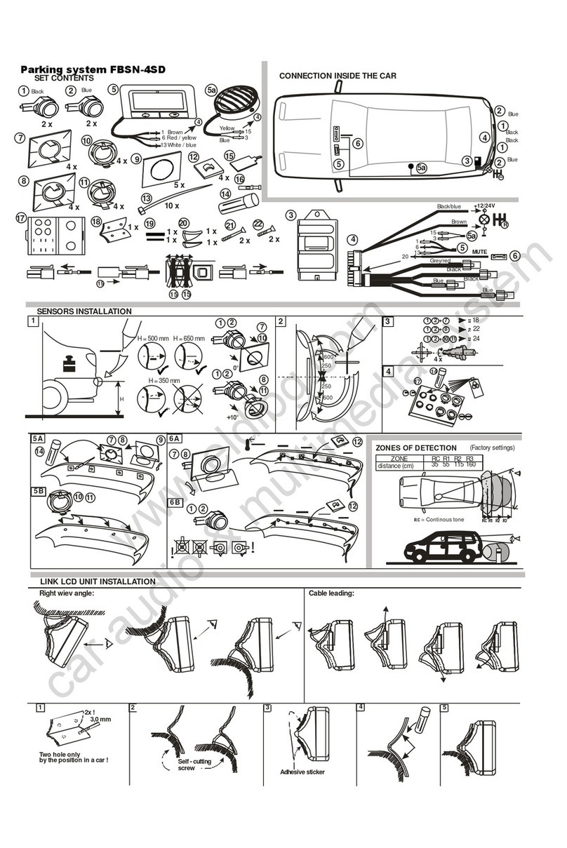
Layout of individual parts of the system is obvious from the picture CONNECTION INSIDE THE CAR.
1. Installation of sensors
•Conditions for layout of sensors in bumpers are in the picture. Choose suitable type of brackets and mark centers of
the holes. For brackets (9) cut out or drill holes ø18mm, for brackets (11) and (12) holes ø24mm, for brackets (25)
holes ø22mm.
•Paint the sensors, perhaps even brackets (11), (12) according to the color of the bumper. Use carton shield (19).
Before painting, apply suitable primer for plastics or Primer (15).
•Apply Primer (15) on the brackets (9) or (25). Get it dry for at least 1 minute. Stick the bonding tapes (10).
•Before sticking of the brackets to the bumper clean surroundings of the holes and apply Primer (15). Get it dry for
at least 1 minute. Place the sensor into the bracket, remove cover foil, insert sensor into the hole and press bracket
toughly. Adjust brackets so that connector of sensor comes out horizontally.
•Place the green sensors into the front bumper, blue sensors into the corners of the rear bumper and black sensors
into the inner positions of the rear bumper.
•Installation of optional TPM sensors into the tires must be done in tire service workshop.
Recommended sensors arrangement: 1 = front left 2 = front right
4 = rear left 3 = rear right
Using Parameters adjustment procedure it is possible to adapt to any other sensors arrangement.
2. Installation of electronic control units (ECUs)
•Electronic control units (ECUs) driving sensors (4) and (7) are intended for installation into plastic bumper (fixed
by 2 screws or plastic fastening belt (16)).
•In case of 12 Volt installation Front ECU can be fed either directly from the car battery or from the ignition clamp.
In case of 24 Volt installation Front ECU must be fed from the ignition clamp. There is also possibility to connect
speed signal to this unit instead of the Display unit (see parameter No.15).
•Rear ECU is fed from reverse gear light clamp.
•Choose appropriate placement of the display holder (20) and install Display unit (6) to the dashboard. LCD display
should be seen perpendicularly by the driver or from angle of 6 hours on the clock dial! Otherwise the LCD
contrast is very poor.
•Display control unit (6) is fed from ignition clamp (black-blue wire). The third (black-yellow) wire of the power
cord (21) is used to connect speed signal to the Display unit.
•It is recommended to check wireless communication quality between ECUs before their final mechanical fixing
(see Remark 3 at the end of this chapter).

3. Registration of front and rear ECUs – so called learning procedure
•Units use wireless communication to transfer data between them. To ensure communication only with its own
ECUs installed in bumpers, Display unit has to learn their unique identification numbers (ID).
•Before first launching of registration process the antenna icon with exclamation sign is displayed.
•Make sure, there is no active electronic parking system of this type in range of cca 100 meters or less.
•If the Front ECU is powered directly from car battery it is necessary to wake up this unit before registration. To do
so, disconnect and reconnect its power cord connector. Now you have 1 minute to proceed to the next step.
•Switch the ignition ON and press and hold for two seconds both pushbuttons of the display unit. „LE“ letters will
appear on the display. Wait until front arrow will appear on the display, announcing that ECU driving front sensors
was successfully registered.
•Shift into the reverse gear and wait until rear arrow will appear announcing that ECU driving rear sensors was
successfully registered.
•!!! If rear arrow icon appears on the display before shifting in reverse gear, than there is another active rear unit
within the RF range. Check the situation and repeat the registration procedure.
•When both ID’s are successfully learned system automatically turns into obstacle indication regime.
•Learning procedure can be interrupted any time by pressing a pushbutton (e.g. when there is no rear ECU
installed).
•Learning procedure can be repeated if necessary. Repeated learning procedure does not cancel individual setting of
parameters.
Rem.:
Error “E1” appears on the display during learning procedure if more than one active front ECUs are present within the RF
range of the display.
Switch ignition OFF/ON and move to better position before repeating learning procedure.
4. Optional speed pulse learning procedure
This procedure is useful if the installer don’t know the exact number of pulses per meter of the speed signal.
This procedure can be used only when the speed signal is connected to the Display unit.
Proceed in the following way:
•Select Service display (parameter No.14) value = 3 (see also Parameters adjustment chapter).
•Switch ignition OFF/ON.
•While driving 50 km/h press left pushbutton on the Display unit.
•Now compare displayed speed with dashboard speedometer reading or a GPS speed data.
•If O.K., press right pushbutton on the Display unit. Display will now turn off until speed decreases under 15 km/h
and an obstacle is detected.
•If not O.K., repeat procedure from the third row.
Rem.: In case of wrong or missing speed signal, error “E3” appears on the display. Stop vehicle and switch OFF/ON
ignition to reset display.

5. Registration of optional TPM sensors
•Due to wireless communication with the tire sensors, display unit has to learn their identification numbers.
•To do so switch the ignition ON and press and hold for four seconds both pushbuttons of the display unit. Pressure
warning symbol together with “LE” letters will appear on the display.
•Drive slowly the car to activate data transmission from TPM sensors. Registered tires are displayed on the car icon.
•Procedure is finished when all four tire sensors have been registered or by switching ignition OFF (if not all
sensors are in disposal). Since now, all registered tires are monitored during vehicle drive.
•Average pressure measured in front / rear tires during registration is stored and used as required front / rear tire
pressure. You can change this value whenever later – see parameters No. 16, 17.
Rem.: Error “E2” appears on the display in case of catching transmission from more than one sensor of the same number
(sensors are numbered 1 2 3 4).
Rem. 1:
Check if setting of parameters No. 8 and 9 (meaning numbering direction of harness/ side position of ECU) is in conformity
with real situation. System is preset for ECU`s installation on the left side of the vehicle. Change these parameters if needed
- see the chapter Parameters adjustment.
Rem. 2:
Select appropriate color of display illumination by parameter No. 10 adjustment.
Rem. 3:
It is recommended to check quality of wireless communication between all ECUs. Select Service display (parameter No.14)
value = 1 to do this. Waves on antenna icon will blink visualizing communication between ECUs. This blinking should be
periodical without visible delays. If not, change Display unit position or position of ECUs driving sensors.
Rem. 4:
If vehicle speed signal is connected to the parking system it is recommended to set parameter 13 value to 0 (time window
function not activated).

Parameters adjustment
Parameters setup is stored inside the Display unit (Master).
All parameter values can be displayed on the Display unit or changed using its pushbuttons.
WARNING! Unprofessional manipulation with parameters can seriously limit utility of device!
To activate Parameters adjustment state press and hold any pushbutton until “SET” appears on the display.
Display shows parameter number and letter “F“ or “C”:
F
means FACTORY SETTING
C
means CUSTOM SETTING – if at least one parameter is set differently from Factory Setting
Some other icons appear on the display to help remember the meaning of chosen parameter.
Now choose desired parameter by means of buttons.
By long push of whichever button the value of chosen parameter is displayed. Value is blinking.
Change the value of parameter by means of buttons.
By long push of whichever button new value is stored and the number of chosen parameter is displayed again.
Switching the ignition OFF terminates Parameters adjustment state.
TO RESTORE FACTORY SETTINGS:
Push and hold both pushbuttons for 2 seconds being in Parameters adjustment state.

Parameters review
NUMBER DESCRIPTION RANGE FACT. SET. NOTE
1 volume of the speaker 0, 1, 2 2 0=off, 1=low, 2=high
2 range of front central sensors 50 - 95 [cm] 80
3 range of rear central sensors 120 - 180 [cm] 160 display shows 20 - 80
4 range of corner sensors 50 - 95 [cm] 60
5 front STOP zone width 35 - 50 [cm] 35
6 rear STOP zone width 35 - 70 [cm] 35
7 front obstacle acoustical indication 0, 1 0 0 = nearing obstacle only
1 = also static obstacles
8 position of front ECU driving sensors 0, 1 0 0 / 1 = left / right
9 position of rear ECU driving sensors 0, 1 0 0 / 1 = left / right
10 color of display illumination 1 - 5 3 1 = red, 2 = green
3 = blue, 4 = amber, 5 = white
11 suppression of spare wheel indication 0, 1, 2, 3 0 see Problems solving
12 number of speed signal pulses per meter 1.0 - 25.0 [pulses/m] 3.0
13 Time window for front sensors 0, 10 - 60 [s] 20 0 = function not activated
14 Service display 0, 1, 2, 3, 4, 5 0 0 = function not activated
1 = communication check
2 = display vehicle speed during drive**
3 = speed pulse learning**
4 = display SW version*
5 = TPM communication check***
15 speed signal attachment 0, 1 0 0 / 1 = display / front ECU
16 front tires required pressure 1.5 – 6.0 [bar] -
17 rear tires required pressure 1.5 – 6.0 [bar] -
18 sensor Number inside Front Left tire 1 - 4 1
19 sensor Number inside Front Right tire 1 - 4 2
20 sensor Number inside Rear Right tire 1 - 4 3
21 sensor Number inside Rear Left tire 1 - 4 4
Note: If no TPM sensors are registered, parameters no. 16 – 21 will not be displayed.
* rem: Software version (0 – 9) is displayed by the small digit of the display numerical field.
**rem: Only when speed signal is attached to the display unit.
***rem: Percentage of successful communications for individual wheels is displayed instead of pressure (after 5 minutes
drive and later).

Problems solving
•If any sensor is faulty, segment in its position is blinking.
Change faulty sensor as soon as possible, system is not fully functional.
•If irregular false obstacle indication occurs, it can be one of the following problems:
Frost on sensors Clean sensors
Sensors are placed too low Use angle brackets (12) or (25) to tilt axe of sensors upwards
Rear side of some sensor is in contact Create separation between sensor and vehicle body
with vehicle chassis
•If any protruding part in the rear of the vehicle causes unwanted obstacle indication (e.g. spare wheel, towing hook…),
increase step by step parameter 11 value from 0 (Factory Setting) until problem is solved.

Technical specifications
Sensors and
ECUs driving sensors Display unit
---------------------------------------------------------------------------------------------------------------------------------------
Supply voltage 9 - 30 V 9 - 30 V
Current consumption when ignition is ON 100 mA max. 100 mA max.
Current consumption when ignition is OFF
and Front ECU connected to car battery 5 – 6 mA (only front unit) -
Range of operating temperatures -25 ... +80 °C (parking sensors) -20 ... +70 °C
Frequency of ultrasound 40 kHz
Communication frequency 434 MHz 434 MHz
TPM sensor’s battery life time min. 5 years (typically 10 years)
TPM sensor’s operating temperature -40 … +125 °C
TPM sensor’s operating pressure 0 – 7.0 bar
Weight of TPM sensor 26 g
The product has been tested against the following standards and specifications:
- EN 300 220-1 V1.1.1 (2006-04) Electromagnetic compatibility and Radio spectrum Matters (ERM)
Test report Ref. No. 8551-PT-R113-09
- EN 60950-1:2006 Safety of information technology equipment.
Test report Ref. No. 8551-PT-B113-09
The product is marked with the CE marking according to the directive 1999/5/EC:
EC-type Approval certificate with regard to Directive 72/245/EEC, as last amended by 2009/19/EC
e8*72/245*2009/19*0095*00
EC type-approval mark affixed on ESA:
Testing of spray water resistance conformity : DIN 40 050 – Part 9 and VW 60258 – paragraph 3.4
Technical report No.: 260305-08-TAC
Degree of protection of parts of electronic parking system - FBSN-8RF
(electronic control unit inside a splash proof box): IP66
Technical report No.: 09.0322-6
Valid for products with: display unit DMS4-RF SW 06.3
rear unit FBSN-4RF SW05 and SW05.1
front unit FBSN-4FRF SW06
21/01/2011 (z.1002)
e8
03 0095
Table of contents
Other APRI Automobile Electronic manuals
Popular Automobile Electronic manuals by other brands

LUTZ AUTO
LUTZ AUTO LTZ-80-OBD-SCREEN operating instructions

IXIT
IXIT BEEPER manual

Car-Systems
Car-Systems Parktronic system Volkswagen Golf MK7 Assembly manual

Peripheral Electronics
Peripheral Electronics Aux2Car instruction manual

TypeS
TypeS BT57799 Care & use instructions

CANchecked
CANchecked VADpro VAD15 installation guide